Download as PDF, PPTX

![29-Aug-02 4
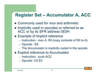
Programmer’s View – Register Set
l Registers
– A, B, R0 to R7 : 8 bit registers
– DPTR : [DPH:DPL] 16 bit register
– PC : Program Counter (Instruction Ptr) 16bits
– 4 sets of register bank R0-R7
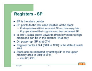
– Stack pointer SP
– PSW : Program Status Word (a.k.a Flags)
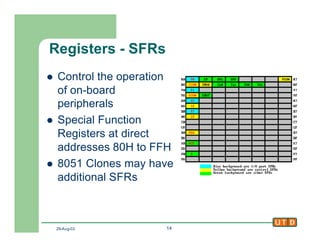
– SFR : Special Function Registers
l Control the on-board peripherals](https://image.slidesharecdn.com/class2-141216232306-conversion-gate01/85/Class2-4-320.jpg)
![29-Aug-02 9
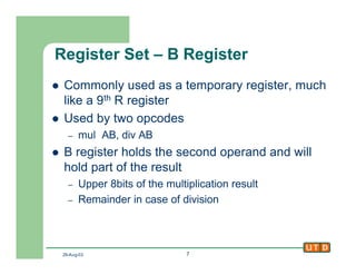
Registers - DPTR
l 16 bit register, called Data Pointer
l Used by commands that access external
memory
l Also used for storing 16bit values
mov DPTR, #data16 ; setup DPTR with 16bit ext address
movx A, @DPTR ; copy mem[DPTR] to A
l DPTR is useful for string operations, look up
table (LUT) operations](https://image.slidesharecdn.com/class2-141216232306-conversion-gate01/85/Class2-9-320.jpg)
![29-Aug-02 17
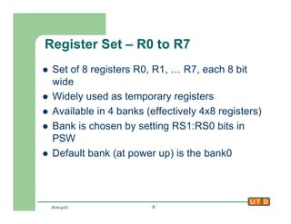
8051 Assembly Introduction
l Assembly statement structure
[label:] opcode [operands] [;comment]
l Example
start: mov A, #D0H ;code starts here
l Assembler directives
– ORG xxxxH : origin, start assembling at xxxxH
– EQU : define a constant
l count EQU 25
– DB : define byte, defines data
l DATA1: DB 28
l DATA2: DB “hello world”
– END : end of assembly file](https://image.slidesharecdn.com/class2-141216232306-conversion-gate01/85/Class2-17-320.jpg)
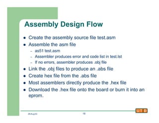
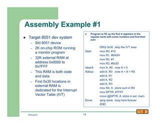

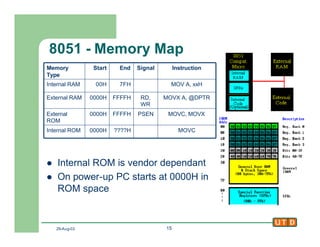
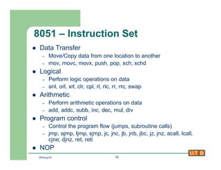
This document provides an introduction to the 8051 microcontroller architecture, including its internal registers, instruction set, and memory map. It discusses the programmer and hardware designer views of the 8051. The register set includes accumulators, registers, data pointers, program counters, stack pointers, and status flags. An overview of 8051 assembly programming is provided, including basic syntax, directives, and the design flow from writing assembly code to downloading the executable onto a board. An example assembly program is presented to demonstrate filling registers and calculating their sum.