The document discusses Assembly Language Programming of the 8051 microcontroller. It covers the following key points in 3 sentences:
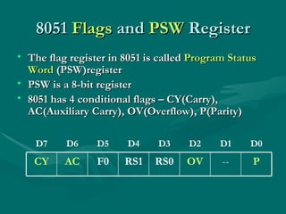
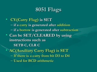
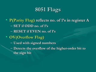
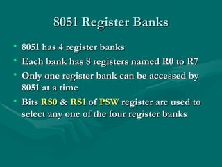
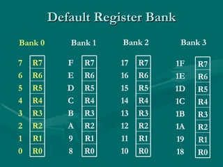
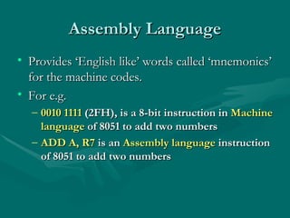
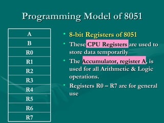
Assembly language uses mnemonics to represent machine code instructions and provides a lower level of programming than high-level languages. The 8051 has 8-bit registers including the accumulator register A used for arithmetic, and 4 status flags in the PSW register for carry, overflow, auxiliary carry, and parity. Assembly language programs are assembled into machine code using an assembler and can access different register banks by setting bits in the PSW register.
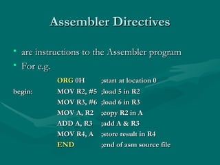
![Assembly Language program Consists of a series of Assembly language instructions Structure of Assembly Language Has four fields [label:] mnemonic [operands] [;comments] start: MOV R5, #25H ;load 25H in R5 MOV A, #5 ;load 5 in A ADD A, R5 ;add A & R5](https://image.slidesharecdn.com/1347-assemblylanguageprogrammingof8051-100523023308-phpapp01/85/1347-Assembly-Language-Programming-Of-8051-6-320.jpg)