1. Engineering drawing is the fundamental means of communication in engineering and is used to convey ideas and specify object shapes and sizes.
2. Drawing instruments like T-squares, set squares, compasses, and dividers are used to prepare drawings easily and accurately. Quality instruments are essential for achieving desirable accuracy.
3. Practice is important for learning engineering drawing - with more practice, students can attain not only subject knowledge but also speed and proficiency in drafting skills like accuracy, lettering, and neatness.


![Department of Industrial
Engineering and management ENGINEERING DRAWING
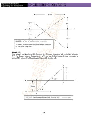
P
TRUE LENGTH
( FIGURE – C )
A
30
ISOMETRIC LENGTH
45
B D
C
( FIGURE – D )
ISOMETRIC LENGTH
15
A B
TRUE LENGTH
45
ISOMETRIC DRAWING OR ISOMETRIC VIEW
If the foreshortening of the isometric lines in an isometric projection is disregarded and instead,
the true lengths are marked, the view obtained [fig.- E (iii)] will be exactly of the same shape
but larger in proportion (about 22.5%) than that obtained by the use of the isometric scale as in
fig.- E (ii). Due to the ease in construction and the advantage of measuring the dimensions
directly from the drawing, it has become a general practice to use the true scale instead of the
isometric scale.
69](https://image.slidesharecdn.com/engdraw-121129165546-phpapp02/85/Eng-draw-70-320.jpg)