Contents
1. Overview: AutomationSystems
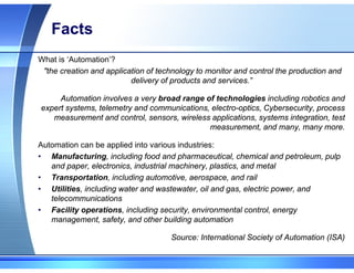
Facts
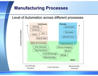
Manufacturing Processes
Processes Control
Control Strategies
System Architecture
2. Automation Network
3. Controllers
3.
Facts
What is ‘Automation’?
"thecreation and application of technology to monitor and control the production and
delivery of products and services.”
Automation involves a very broad range of technologies including robotics and
expert systems, telemetry and communications, electro-optics, Cybersecurity, process
measurement and control, sensors, wireless applications, systems integration, test
measurement, and many, many more.
Automation can be applied into various industries:
• Manufacturing, including food and pharmaceutical, chemical and petroleum, pulp
and paper, electronics, industrial machinery, plastics, and metal
• Transportation, including automotive, aerospace, and rail
• Utilities, including water and wastewater, oil and gas, electric power, and
telecommunications
• Facility operations, including security, environmental control, energy
management, safety, and other building automation
Source: International Society of Automation (ISA)
4.
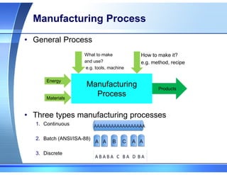
Manufacturing Process
• GeneralProcess
• Three types manufacturing processes
1. Continuous
2. Batch (ANSI/ISA-88)
3. Discrete
Manufacturing
Process
What to make
and use?
e.g. tools, machine
How to make it?
e.g. method, recipe
Energy
Materials
Products
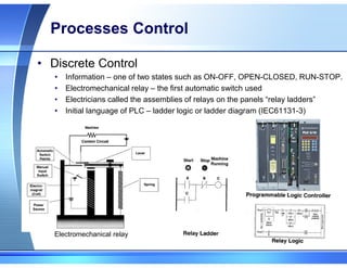
Processes Control
• DiscreteControl
• Information – one of two states such as ON-OFF, OPEN-CLOSED, RUN-STOP.
• Electromechanical relay – the first automatic switch used
• Electricians called the assemblies of relays on the panels “relay ladders”
• Initial language of PLC – ladder logic or ladder diagram (IEC61131-3)
Electromechanical relay
7.
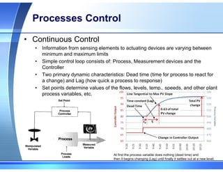
Processes Control
• ContinuousControl
• Information from sensing elements to actuating devices are varying between
minimum and maximum limits
• Simple control loop consists of: Process, Measurement devices and the
Controller
• Two primary dynamic characteristics: Dead time (time for process to react for
a change) and Lag (how quick a process to response)
• Set points determine values of the flows, levels, temp., speeds, and other plant
process variables, etc.
At first the process variable does nothing (dead time) and
then it begins changing (Lag) until finally it settles out at a new level.
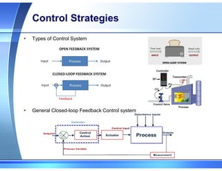
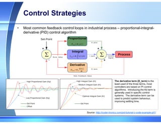
Control Strategies
• Mostcommon feedback control loops in industrial process – proportional-integral-
derivative (PID) control algorithm
The derivative term (D_term) is the
least used of the three terms, most
controllers are based on PI control
algorithms. Introducing the Kd term is
generally used in specific control
systems. The derivative term can be
used to predict system behaviour,
improving settling time.
Source: http://coder-tronics.com/pid-tutorial-c-code-example-pt1/
10.
Control Strategies
• 90-95%of the Industrial market applications based
on PID
• Why need other control strategies, e.g. Model
Predictive control (MPC)
Model Predictive Control (MPC) versus
Proportional-Integrate-Derivative (PID) control.
When using MPC control, the driver determines
('calculates') his driving strategy before departure
after careful investigation of the road. When he
uses the correct information (input variables), he
stays on the road (yellow car), but small errors in
input variables can lead the car in the wrong
direction (red and blue cars). The drivers using PID
control readjust their driving strategy often by
frequently calculating the difference with the 'ideal'
track.
Source:
https://openi.nlm.nih.gov/detailedresult.php?img=PM
C2784347_cc8023-1&req=4
11.
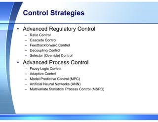
Control Strategies
• AdvancedRegulatory Control
– Ratio Control
– Cascade Control
– Feedbackforward Control
– Decoupling Control
– Selector (Override) Control
• Advanced Process Control
– Fuzzy Logic Control
– Adaptive Control
– Model Predictive Control (MPC)
– Artificial Neural Networks (ANN)
– Multivariate Statistical Process Control (MSPC)
12.
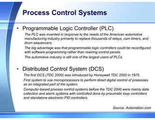
Process Control Systems
•Programmable Logic Controller (PLC)
The PLC was invented in response to the needs of the American automotive
manufacturing industry primarily to replace thousands of relays, cam timers, and
drum sequencers.
The big advantage was that programmable logic controllers could be reconfigured
with software programming rather than rewiring control panels.
The automotive industry is still one of the largest users of PLCs.
• Distributed Control System (DCS)
The first DCS (TDC 2000) was introduced by Honeywell TDC 2000 in 1975.
First system to use microprocessors to perform direct digital control of processes
as an integrated part of the system.
Computer-based process control systems before the TDC 2000 were mainly data
collection and alarm systems with controlled done by pneumatic loop controllers
and standalone electronic PID controllers.
Source: Automation.com
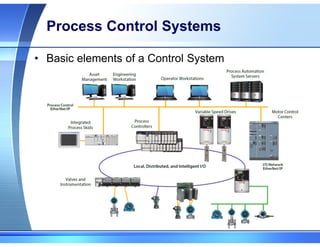
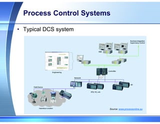
Process Control Systems
•Basic elements of a Control System
1. Input/Output (I/O)
1. Pneumatic interface (3-15psi)
2. Analogue (4-20mA)
3. Discrete IO, Digital (On-Off, 0-5V)
2. Sensor Network
1. Actuator Sensor interface (AS-i)
2. CC-Link LT
3. DeviceNet
4. Ethernet/IP
5. FOUNDATION Fieldbus
6. Highway Addressable Remote Transducer (HART)
7. Modbus
8. Profibus
9. Wireless, e..g wirelessHART, ISA100, Zigbee
15.
Process Control Systems
•Elements of a Control System
3. Control Level Network
1. CC-Link
2. BACnet or LonWorks for Building Automation applications
3. Ethernet/IP
4. Modbus/TCP
5. PROFINET
6. FOUNDATION Fieldbus
4. Human Machine Interface (HMI)
1. Operator Workstation
2. System Workstation
3. Application Servers, e.g. OLE for Process Control (OPC)
4. Supervisory control and Data Acquisition (SCADA)
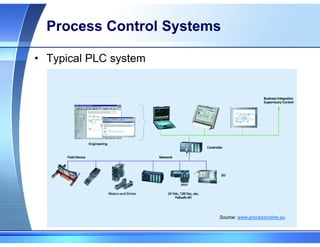
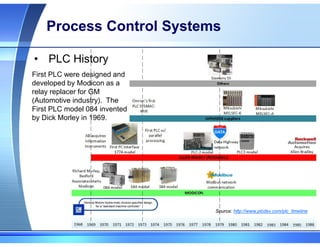
Process Control Systems
FirstPLC were designed and
developed by Modicon as a
relay replacer for GM
(Automotive industry). The
First PLC model 084 invented
by Dick Morley in 1969.
Source: http://www.plcdev.com/plc_timeline
• PLC History
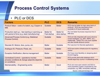
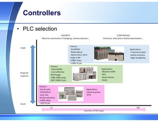
Process Control Systems
•PLC or DCS
Factors PLC DCS Remarks
Product Value – costs of a batch, e.g. Copper or
Milk
Suitable Better DCS may be better for high value batch of
products. DCS has redundancy from
controller to IO level traditionally
Production start-up – fast starting or warming up
with period of time (e.g. steel manufacturing)
Better for
Fast startup
Better for
slow startup
PLC are faster & process response time in
Milli-secs
Advanced Process Control (e.g. Statistical
Process Control)
Suitable Better DCS are fully integrated with some advance
control strategies, e.g. SPC, MSPC, etc.)
traditionally. Today’s PLC are more capable
and also handle advance control
Discrete IO, Motors, fans, pump, etc. Better Suitable PLC was born for Discrete applications
Analogue IO, Pressure, Flows, etc. Suitable Better DCS have built-in infrastructure for regulatory
control
Exception Notification, Alarms management Better Suitable PLC have more flexibility on designing alarm
& event logging
Centralized Control – operations monitor
process conditions & change setpoints depends
on conditions
Suitable Better DCS provide plant-wide database which
handle large loop counts in multitasking mode
Maintainability – Engineering works Better Good PLCs are more open solution and DCS is
more proprietary system (supported by own
companies, e.g. ABB, Honeywell) relatively
Source: www.pennenergy.com
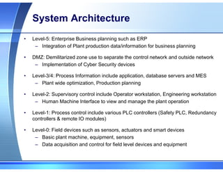
System Architecture
• Level-5:Enterprise Business planning such as ERP
– Integration of Plant production data/information for business planning
• DMZ: Demilitarized zone use to separate the control network and outside network
– Implementation of Cyber Security devices
• Level-3/4: Process Information include application, database servers and MES
– Plant wide optimization, Production planning
• Level-2: Supervisory control include Operator workstation, Engineering workstation
– Human Machine Interface to view and manage the plant operation
• Level-1: Process control include various PLC controllers (Safety PLC, Redundancy
controllers & remote IO modules)
• Level-0: Field devices such as sensors, actuators and smart devices
– Basic plant machine, equipment, sensors
– Data acquisition and control for field level devices and equipment
22.
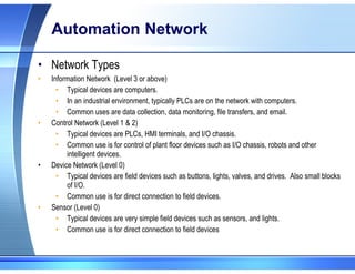
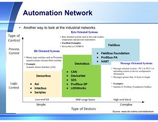
Automation Network
• NetworkTypes
• Information Network (Level 3 or above)
• Typical devices are computers.
• In an industrial environment, typically PLCs are on the network with computers.
• Common uses are data collection, data monitoring, file transfers, and email.
• Control Network (Level 1 & 2)
• Typical devices are PLCs, HMI terminals, and I/O chassis.
• Common use is for control of plant floor devices such as I/O chassis, robots and other
intelligent devices.
• Device Network (Level 0)
• Typical devices are field devices such as buttons, lights, valves, and drives. Also small blocks
of I/O.
• Common use is for direct connection to field devices.
• Sensor (Level 0)
• Typical devices are very simple field devices such as sensors, and lights.
• Common use is for direct connection to field devices
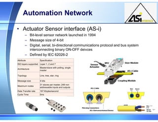
Automation Network
• ActuatorSensor interface (AS-i)
– Bit-level sensor network launched in 1994
– Message size of 4-bit
– Digital, serial, bi-directional communications protocol and bus system
interconnecting binary ON-OFF deivces
– Defined by IEC 62026-2
Attribute Specification
ISO layers supported Layer 1, 2 and 7
Architecture
Master/slave with polling, single
master
Topology Line, tree, star, ring
Message size 4 bits
Maximum nodes
31 slaves per master, 248 non
addressable inputs and outputs
Data Transfer rate 167 Kbytes/second
Cycle Time 5ms
25.
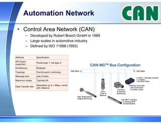
Automation Network
• ControlArea Network (CAN)
– Developed by Robert Bosch GmbH in 1989
– Large scales in automotive industry
– Defined by ISO 11898 (1993)
Attribute Specification
ISO layers
supported
Partial layer 1, full layer 2
Architecture Multipeer
Topology Point-to-point, multi-drop
Message size upto 8 bytes
Maximum nodes Typically 64
Data Transfer rate
Selectable up to 1 Mbps, varies
with distance
26.
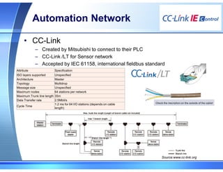
Automation Network
• CC-Link
–Created by Mitsubishi to connect to their PLC
– CC-Link /LT for Sensor network
– Accepted by IEC 61158, international fieldbus standard
Attribute Specification
ISO layers supported Unspecified
Architecture Master
Topology Multidrop
Message size Unspecified
Maximum nodes 64 stations per network
Maximum Trunk line length 35m
Data Transfer rate 2.5Mbit/s
Cycle Time
1.2 ms for 64 I/O stations (depends on cable
length)
Source:www.cc-link.org
27.
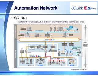
Automation Network
• CC-Link
–Different versions (IE, LT, Safety) are implemented at different area
Source:www.cc-link.org
28.
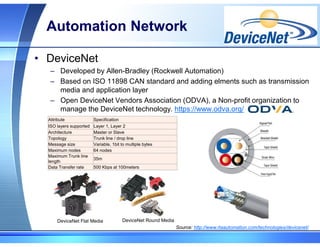
Automation Network
• DeviceNet
–Developed by Allen-Bradley (Rockwell Automation)
– Based on ISO 11898 CAN standard and adding elments such as transmission
media and application layer
– Open DeviceNet Vendors Association (ODVA), a Non-profit organization to
manage the DeviceNet technology. https://www.odva.org/
Source: http://www.rtaautomation.com/technologies/devicenet/
DeviceNet Flat Media DeviceNet Round Media
Attribute Specification
ISO layers supported Layer 1, Layer 2
Architecture Master or Slave
Topology Trunk line / drop line
Message size Variable, 1bit to multiple bytes
Maximum nodes 64 nodes
Maximum Trunk line
length
35m
Data Transfer rate 500 Kbps at 100meters
29.
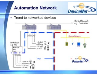
Automation Network
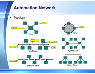
• Trendto networked devices
Control Network
e.g. ControlNet
Remote
I/O
Rack
A
1-5 vDC
4-20 ma
120 vAC
24 vDC
24vdc
509 -BOD
T
A
D D
I/O Network
e.g. RIO
A
1-5 vDC
4-20 ma
120 vAC
24 vDC
24vdc
509 -BOD
T
A
D D
Device Network
24vdc
509 -BOD
T
PRESENT
PAST
30.
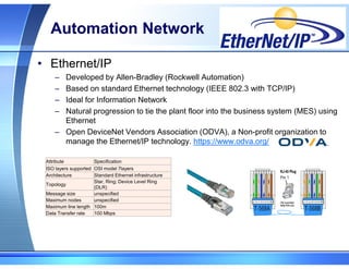
Automation Network
• Ethernet/IP
–Developed by Allen-Bradley (Rockwell Automation)
– Based on standard Ethernet technology (IEEE 802.3 with TCP/IP)
– Ideal for Information Network
– Natural progression to tie the plant floor into the business system (MES) using
Ethernet
– Open DeviceNet Vendors Association (ODVA), a Non-profit organization to
manage the Ethernet/IP technology. https://www.odva.org/
Attribute Specification
ISO layers supported OSI model 7layers
Architecture Standard Ethernet infrastructure
Topology
Star, Ring; Device Level Ring
(DLR)
Message size unspecified
Maximum nodes unspecified
Maximum line length 100m
Data Transfer rate 100 Mbps
31.
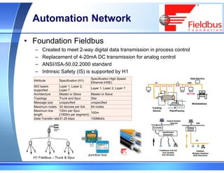
Automation Network
• FoundationFieldbus
– Created to meet 2-way digital data transmission in process control
– Replacement of 4-20mA DC transmission for analog control
– ANSI/ISA-50.02.2000 standard
– Intrinsic Safety (IS) is supported by H1
Junction box
H1 Fieldbus – Trunk & Spur
Attribute Specification (H1)
Specification High Speed
Ethernet (HSE)
ISO layers
supported
Layer 1, Layer 2,
Layer 7
Layer 1, Layer 2, Layer 7
Architecture Master or Slave Master or Slave
Topology Trunk and Spur Star
Message size unspecified unspecified
Maximum nodes 32 devices per link 64 nodes
Maximum line
length
120m per Spur
(1900m per segment)
100m
Data Transfer rate31.25 kbps 100Mbit/s
32.
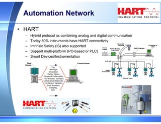
Automation Network
• HART
–Hybrid protocol as combining analog and digital communication
– Today 80% instruments have HART connectivity
– Intrinsic Safety (IS) also supported
– Support multi-platform (PC-based or PLC)
– Smart Devices/Instrumentation
33.
Automation Network
• Modbus
–Serial communication protocol developed by Modicon (Schnedier) in 1979
– Large scales in automotive industry
– Defined by ISO 11898 (1993)
34.
Automation Network
• Profibus
–Developed by Robert Bosch GmbH in 1989
– Large scales in automotive industry
– Defined by ISO 11898 (1993)