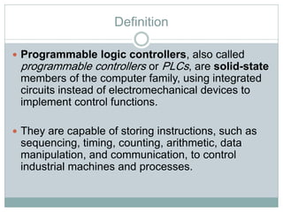
Definition
Programmable logiccontrollers, also called
programmable controllers or PLCs, are solid-state
members of the computer family, using integrated
circuits instead of electromechanical devices to
implement control functions.
They are capable of storing instructions, such as
sequencing, timing, counting, arithmetic, data
manipulation, and communication, to control
industrial machines and processes.
4.
Definition
PLCs areindustrial computers with specially
designed architecture in both their central units (the
PLC itself) and their interfacing circuitry to field
devices (input/output connections to the real world).
Historical Background
GeneralMotors specified the design criteria for the first programmable
controller in 1968.
Their primary goal was to eliminate the high costs associated with
inflexible, relay controlled systems.
Initial Specification included the following:
The new control system had to be price competitive with relay systems.
The system had to be capable of sustaining an industrial environment.
The input and output interfaces had to be easily replaceable.
The control system needed to pass data collection to a central system.
The system had to be reusable.
The method used to program the controller had to be simple
8.
Historical Background
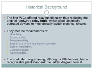
Thefirst PLCs offered relay functionality, thus replacing the
original hardwired relay logic, which used electrically
operated devices to mechanically switch electrical circuits.
They met the requirements of:
Modularity.
Expandability.
Programmability.
Ease of use in an industrial environment.
Ease of installation.
Used less space.
Were reusable.
The controller programming, although a little tedious, had a
recognizable plant standard: the ladder diagram format.
9.
Historical Background
By1971, PLCs were being used to provide relay
replacement as the first steps toward control
automation in other industries, such as food and
beverage, metals, manufacturing, and pulp and
paper.
Many technological advances in the programmable
controller industry continue today. Changes
include both hardware (physical components) and
software (control program) upgrades.
10.
Historical Background:
PLC hardwareenhancements
Faster scan times.
Small, low-cost PLCs with more power.
High-density input/output (I/O) systems.
Intelligent, microprocessor-based I/O interfaces such as
PID, network, and host computer.
Mechanical design improvements have included: rugged
input/output enclosures and input/output systems that have
made the terminal an integral unit.
Special interfaces have allowed certain devices to be
connected directly to the controller, such as thermocouples
and strain gauges.
Peripheral equipment has improved operator interface
techniques
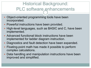
Historical Background:
PLC softwareenhancements
Object-oriented programming tools have been
incorporated.
Powerful instructions have been provided.
High-level languages, such as BASIC and C, have been
implemented.
Advanced functional block instructions have been
implemented for ladder diagram instruction.
Diagnostics and fault detection have been expanded.
Floating-point math has made it possible to perform
complex calculations.
Data handling and manipulation instructions have been
improved and simplified.
13.
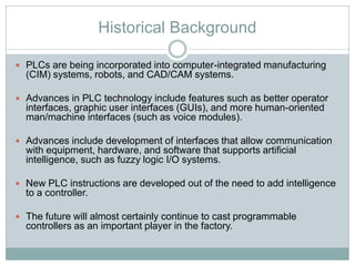
Historical Background
PLCsare being incorporated into computer-integrated manufacturing
(CIM) systems, robots, and CAD/CAM systems.
Advances in PLC technology include features such as better operator
interfaces, graphic user interfaces (GUIs), and more human-oriented
man/machine interfaces (such as voice modules).
Advances include development of interfaces that allow communication
with equipment, hardware, and software that supports artificial
intelligence, such as fuzzy logic I/O systems.
New PLC instructions are developed out of the need to add intelligence
to a controller.
The future will almost certainly continue to cast programmable
controllers as an important player in the factory.
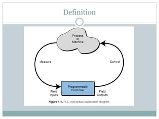
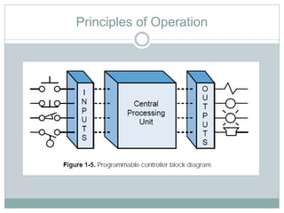
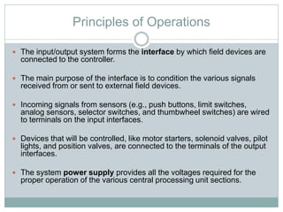
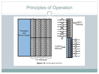
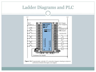
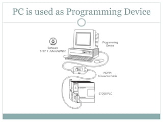
Principles of Operations
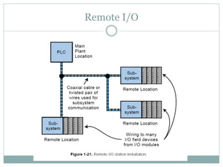
The input/output system forms the interface by which field devices are
connected to the controller.
The main purpose of the interface is to condition the various signals
received from or sent to external field devices.
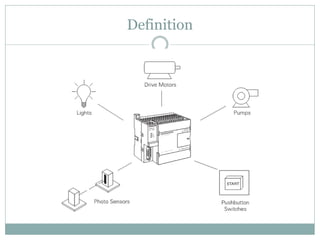
Incoming signals from sensors (e.g., push buttons, limit switches,
analog sensors, selector switches, and thumbwheel switches) are wired
to terminals on the input interfaces.
Devices that will be controlled, like motor starters, solenoid valves, pilot
lights, and position valves, are connected to the terminals of the output
interfaces.
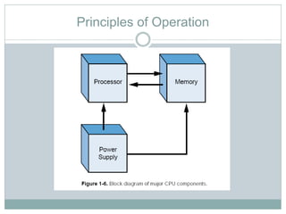
The system power supply provides all the voltages required for the
proper operation of the various central processing unit sections.
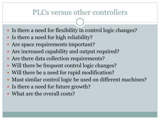
PLCs versus othercontrollers
Is there a need for flexibility in control logic changes?
Is there a need for high reliability?
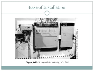
Are space requirements important?
Are increased capability and output required?
Are there data collection requirements?
Will there be frequent control logic changes?
Will there be a need for rapid modification?
Must similar control logic be used on different machines?
Is there a need for future growth?
What are the overall costs?
20.
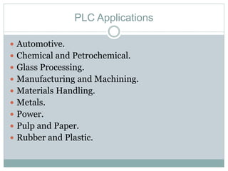
PLC Applications
Automotive.
Chemical and Petrochemical.
Glass Processing.
Manufacturing and Machining.
Materials Handling.
Metals.
Power.
Pulp and Paper.
Rubber and Plastic.
21.
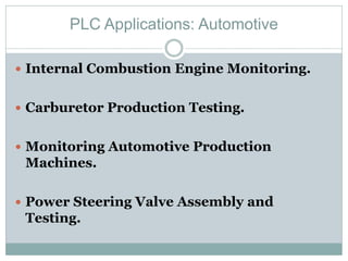
PLC Applications: Automotive
Internal Combustion Engine Monitoring.
Carburetor Production Testing.
Monitoring Automotive Production
Machines.
Power Steering Valve Assembly and
Testing.
22.
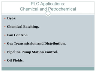
PLC Applications:
Chemical andPetrochemical
Dyes.
Chemical Batching.
Fan Control.
Gas Transmission and Distribution.
Pipeline Pump Station Control.
Oil Fields.
23.
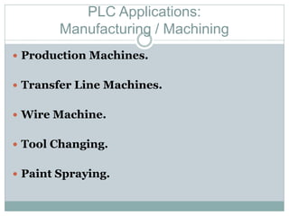
PLC Applications:
Manufacturing /Machining
Production Machines.
Transfer Line Machines.
Wire Machine.
Tool Changing.
Paint Spraying.
24.
PLC Applications: Power
Plant Power System.
Energy Management.
Coal Fluidization Processing.
Compressor Efficiency Control.
25.
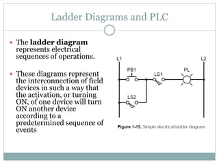
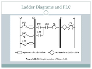
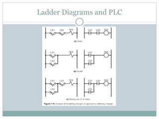
Ladder Diagrams andPLC
The ladder diagram
represents electrical
sequences of operations.
These diagrams represent
the interconnection of field
devices in such a way that
the activation, or turning
ON, of one device will turn
ON another device
according to a
predetermined sequence of
events