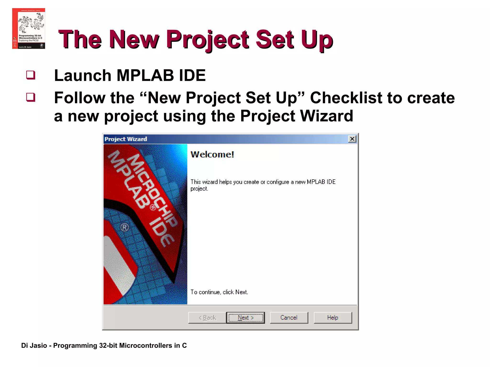
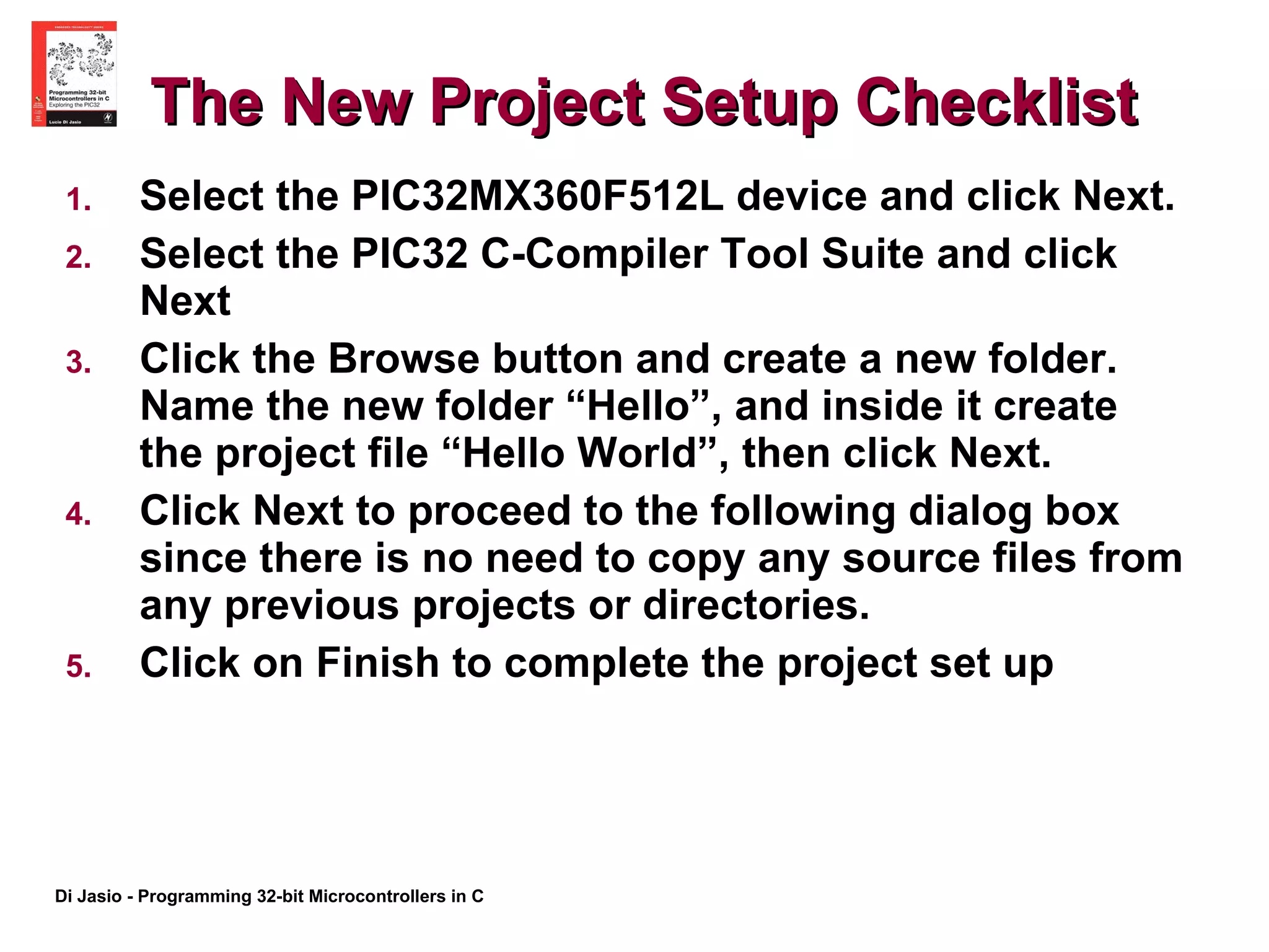
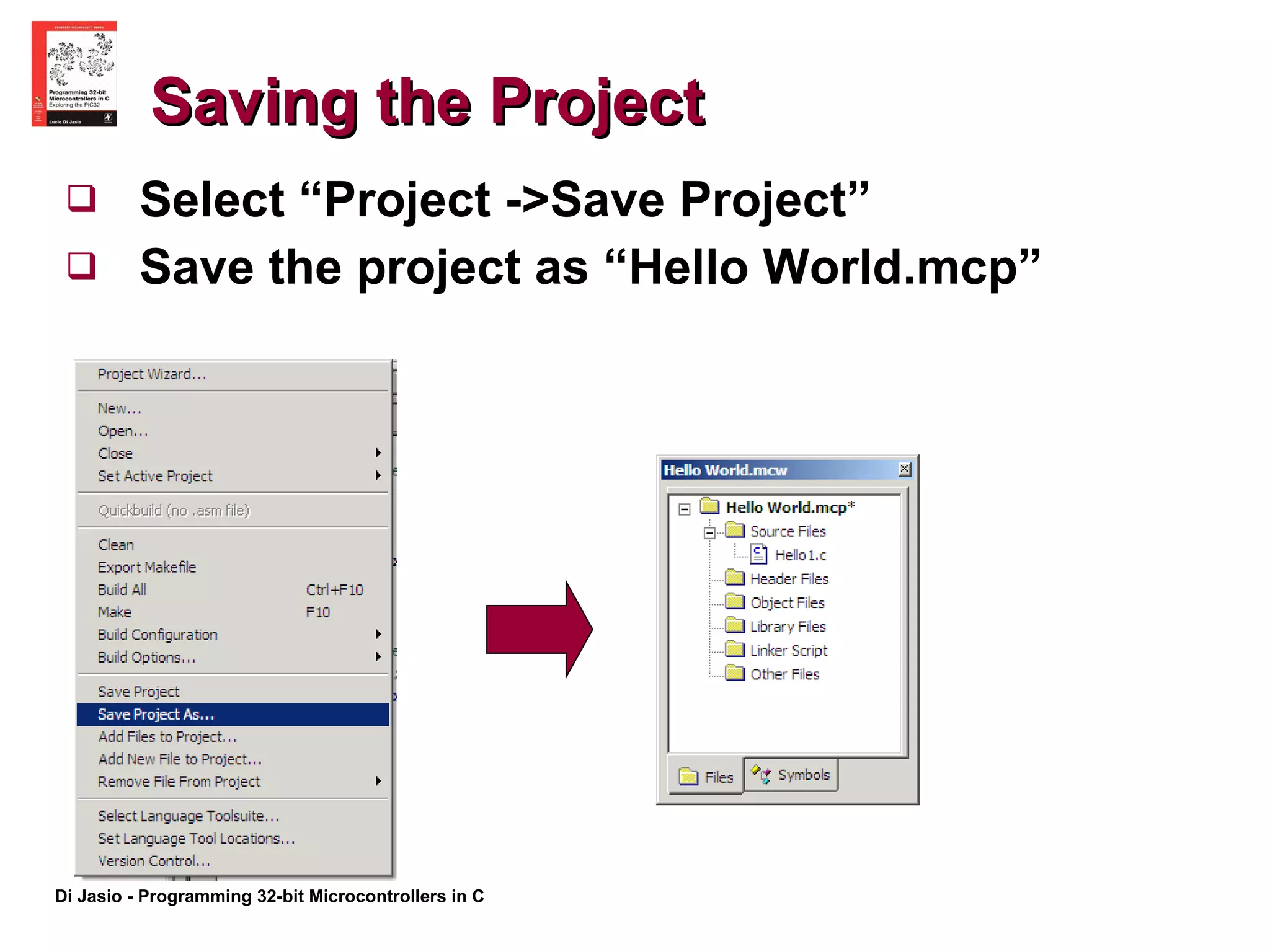
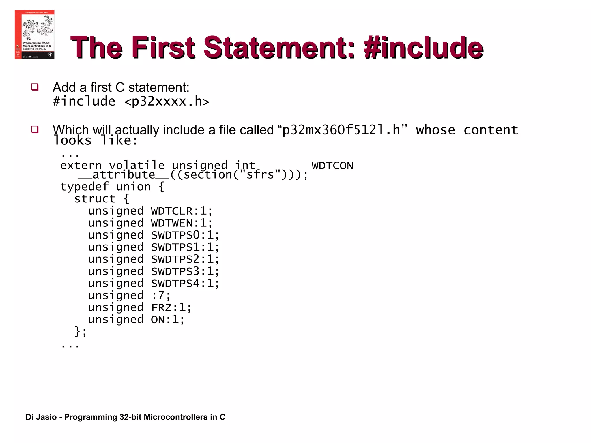
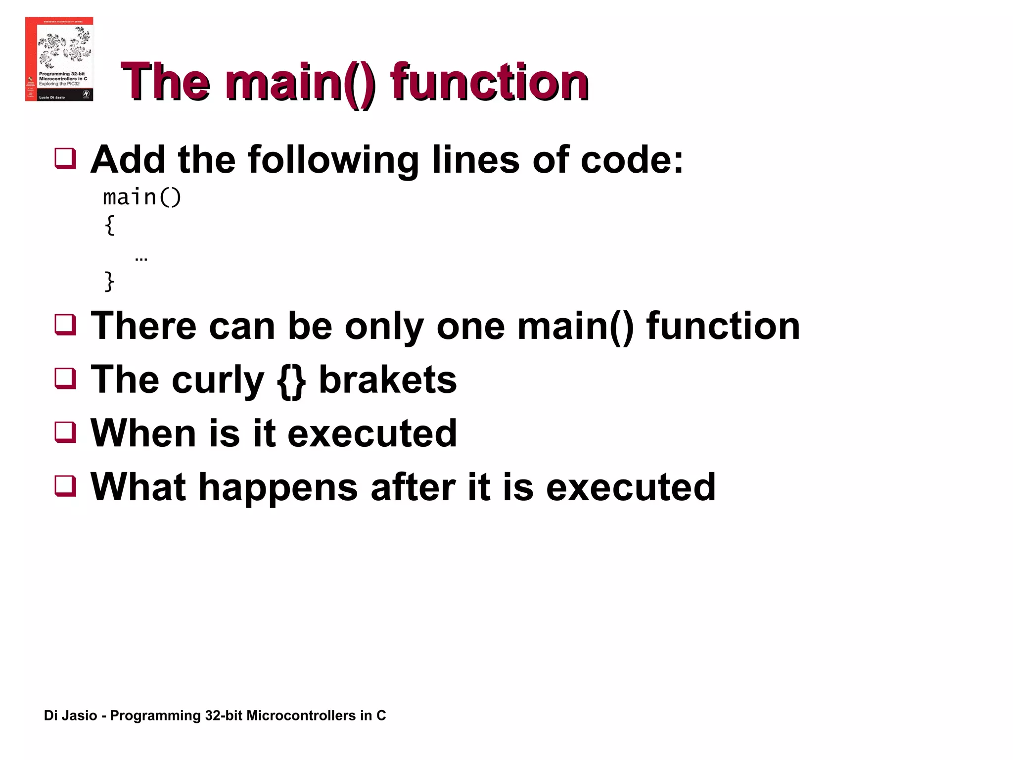
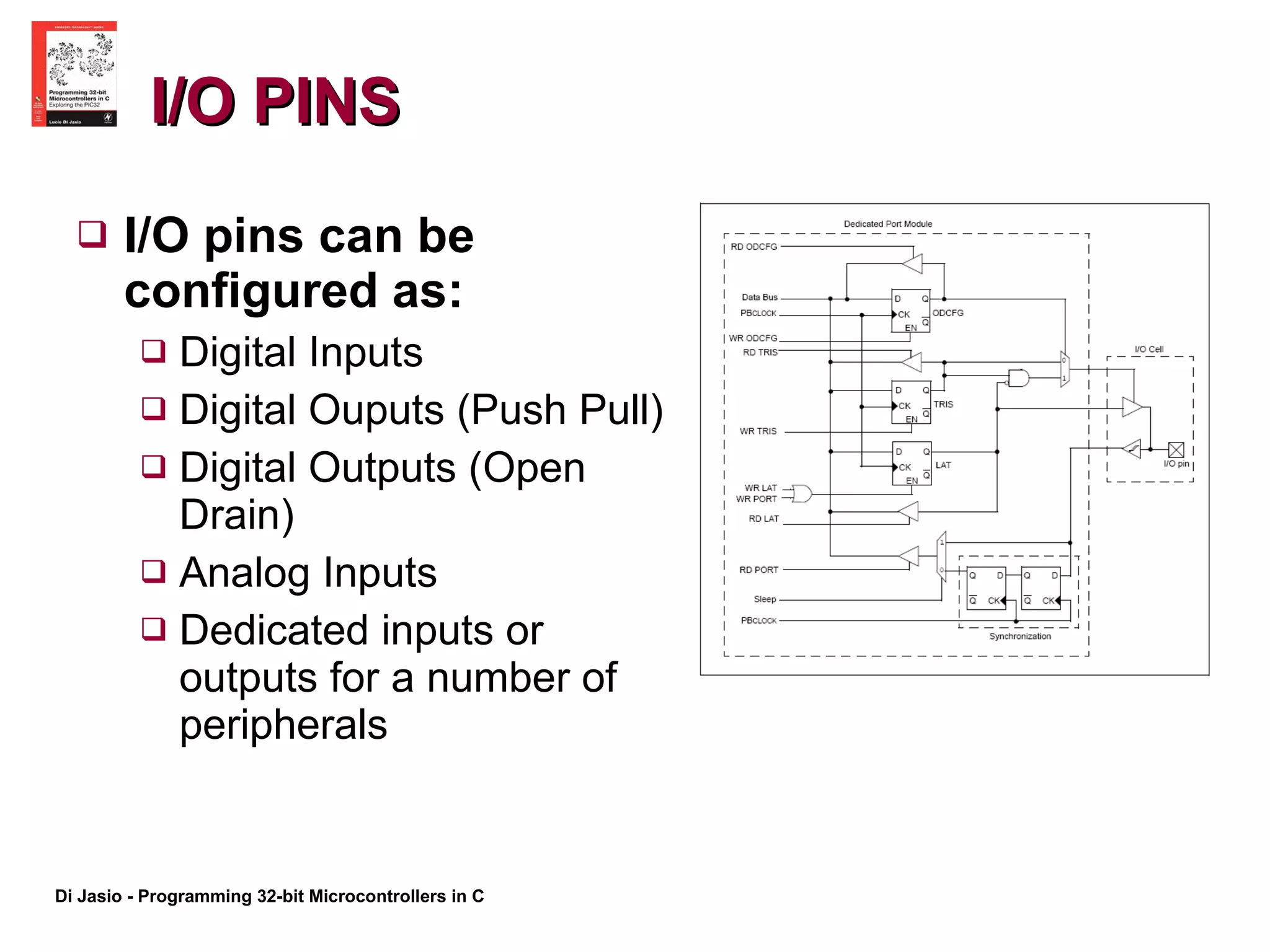
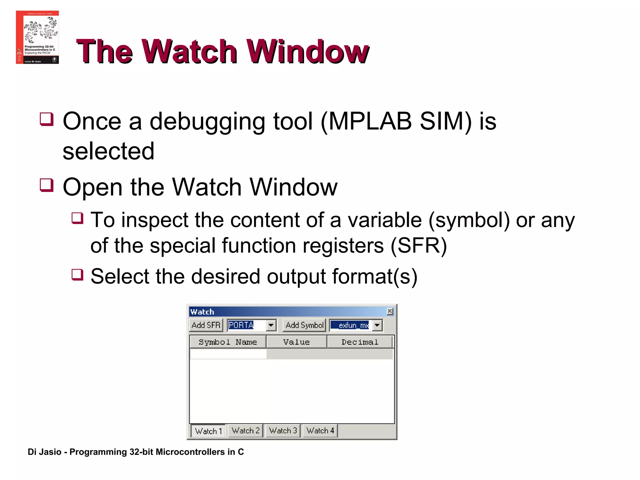
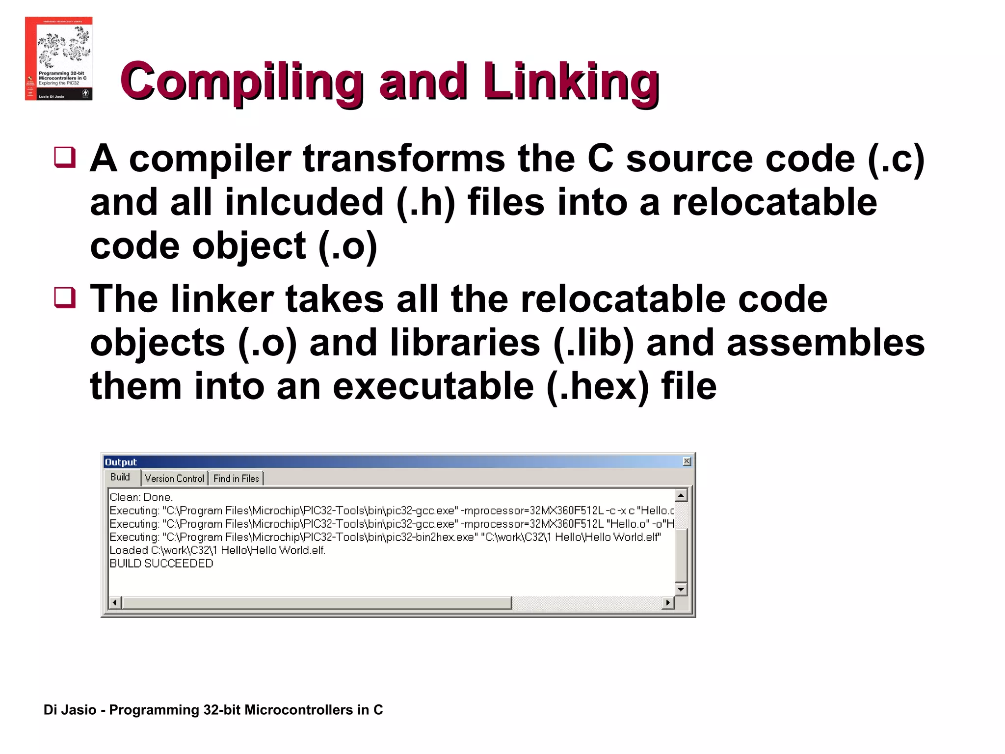
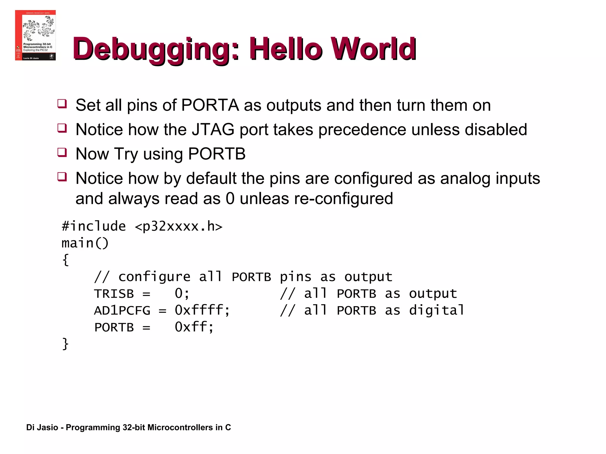
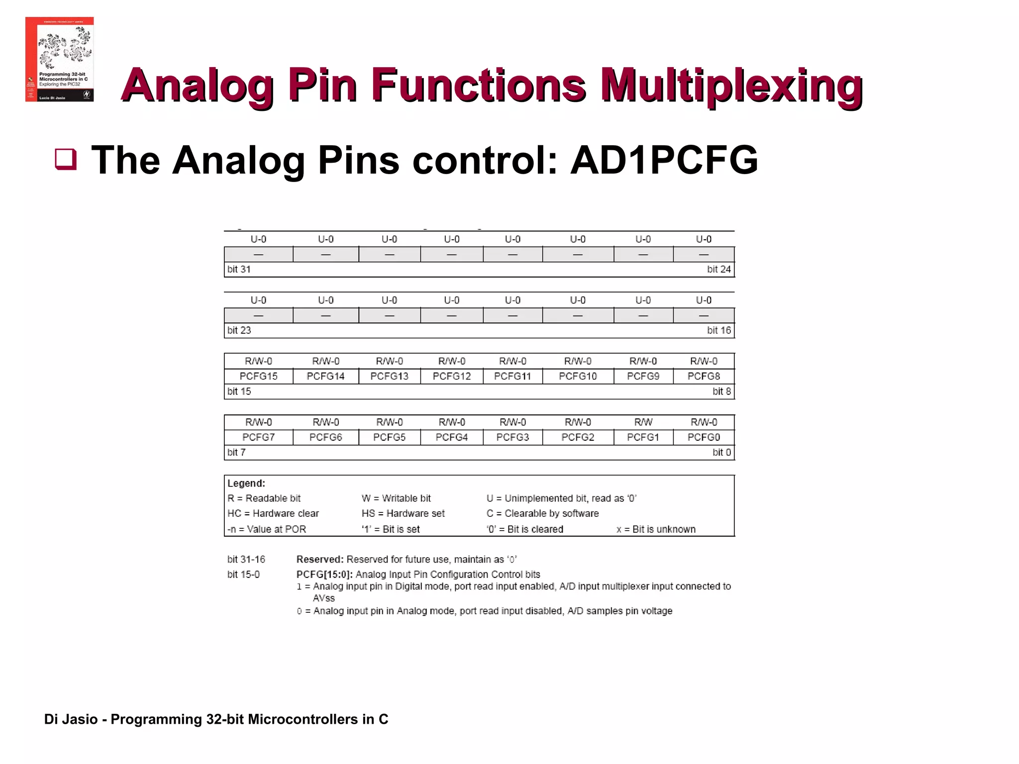
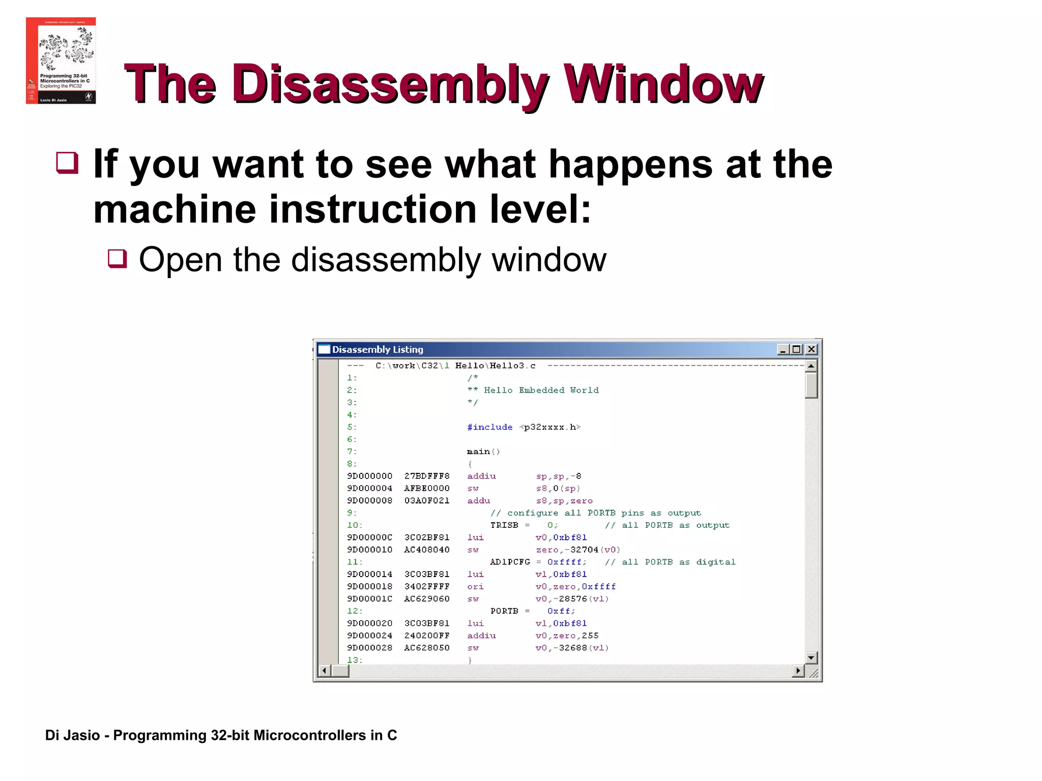
Chapter 1  The Adventure Begins Creating the first project and saying “Hello to the world”
The Plan The first project with MPLAB IDE The project window The editor The output window A first statement  A first complete program Controlling I/Os: Ports and Pins Building the project Using the MPLAB SIM simulator The first debugging experience Hello World!
Preparation The following tools will be used in this lesson: MPLAB IDE, Integrated Development Environment (v8.00 or later, free) MPLAB SIM, free software simulator  (included in MPLAB installation) MPLAB C32, C compiler  (free Student Edition) The following pieces of documentation will be used during this lesson: PIC32MX Datasheet –DS61143 (latest rev.) PIC32MX Family Reference Manual – DS61120  Section 12. I/O Ports Make sure they are available and/or installed and ready to use on your computer. You can download them from Microchip web site at:  http://www.microchip.com/mplab   And  http://www.microchip.com/c32
The New Project Set Up Launch MPLAB IDE  Follow the “New Project Set Up” Checklist to create a new project using the Project Wizard
The New Project Setup Checklist Select the PIC32MX360F512L device and click Next.  Select the PIC32 C-Compiler Tool Suite and click Next Click the Browse button and create a new folder. Name the new folder “Hello”, and inside it create the project file “Hello World”, then click Next. Click Next to proceed to the following dialog box since there is no need to copy any source files from any previous projects or directories. Click on Finish to complete the project set up
The Project Window If not automatically visible, open the Project Window: Select “View-> Project” from the main menu Note: The project window can be made “dockable” so that it will stick to one of the edges of the screen (left)
The Output Window If not automatically visible, open the Output Window: Select “View-> Output” from the main menu Note: The output window can be made “dockable” so that it will stick to one of the edges of the screen (bottom)
The Editor Window Open a new editor window by selecting  “ File->New”, or CTRL+N keyboard shortcut, or by clicking on the corresponding  button in MPLAB standard toolbar.
Creating a Source File Type the following three lines:  /* **  Hello Embedded World!  */ Select “File ->Save As”  Save the file as: “Hello1.c”.  Now right click with your mouse on the editor window to bring up the editor’s context menu  Select the “Add To Project” item.  This will make the Hello1.c file the main source file in your project
Saving the Project Select “Project ->Save Project”  Save the project as “Hello World.mcp”
The First Statement: #include Add a first C statement: #include <p32xxxx.h> Which will actually include a file called “ p32mx360f512l.h” whose content looks like: ... extern volatile unsigned int  WDTCON __attribute__((section(&quot;sfrs&quot;))); typedef union { struct { unsigned WDTCLR:1; unsigned WDTWEN:1; unsigned SWDTPS0:1; unsigned SWDTPS1:1; unsigned SWDTPS2:1; unsigned SWDTPS3:1; unsigned SWDTPS4:1; unsigned :7; unsigned FRZ:1; unsigned ON:1; }; ...
The main() function Add the following lines of code: main()  { … } There can be only one main() function The curly {} brakets When is it executed What happens after it is executed
I/O PINS I/O pins can be configured as: Digital Inputs Digital Ouputs (Push Pull) Digital Outputs (Open Drain) Analog Inputs Dedicated inputs or outputs for a number of peripherals
PORTA and PORTB  Different PORTs group pins with different functions  PORTB for example contains a number of pins that can be configured as analog inputs to the Analog to Digital Converter (ADC) . PORTA contains a number of pins that can be used for the JTAG interface, TRACE function, and the I2C interface Refer to the specific device datasheet for a detailed list of each PORT/pin capabilities
TRIS registers TRIS registers control the direction of each pin (Input/Output) TRISA, TRISB… each port has a corresponding tris register  Setting a bit to 1 configures a pin as Input Clearing a bit to 0 configure the corresponding pin as an output
The Watch Window Once a debugging tool (MPLAB SIM) is selected  Open the Watch Window To inspect the content of a variable (symbol) or any of the special function registers (SFR) Select the desired output format(s)
Compiling and Linking A compiler transforms the C source code (.c) and all inlcuded (.h) files into a relocatable code object (.o) The linker takes all the relocatable code objects (.o) and libraries (.lib) and assembles them into an executable (.hex) file
Using the Simulator Follow the SetUp Checklist Learn the basic debugging options offered by the Simulator Reset Single Step (Over/In) Animation Running Halting
Debugging: Hello World #include <p32xxxx.h> main() { // configure all PORTB pins as output TRISB =  0;  // all PORTB as output AD1PCFG = 0xffff;  // all PORTB as digital PORTB =  0xff; } Set all pins of PORTA as outputs and then turn them on Notice how the JTAG port takes precedence unless disabled Now Try using PORTB Notice how by default the pins are configured as analog inputs and always read as 0 unleas re-configured
Analog Pin Functions Multiplexing The Analog Pins control: AD1PCFG
Summary In this lesson we learned: How to create a new project How to create our first C source file How to build a project using the MPLAB C32 compiler About PINs and PORTs How to configure and control simple digital output pins How to configure and use the MPLAB SIM simulator
Advanced Material
The Disassembly Window If you want to see what happens at the machine instruction level:  Open the disassembly window
The Memory Gauge If you want to see how much memory RAM and FLASH is being used by the project Open the Memory Gauge Window
Notes for the PIC MCU Experts The PIC32 PORTS are not necessarily 32-bit large. In fact most PORTS are 16-bit at the most. The PIC32 PORTS are designed to be compatible with the 8-bit and 16-bit PIC PORTS I/O PORT control in C is easy Use the LATx registers to control directly the output latches
Tips and Tricks Interfacing to 5V input and output signals is possible with some caution: Digital Input pins are 5V tolerant Digital Output pins can be configured as Open Drain Use the ODCx registers to configure an output pin for Open Drain mode. Watch Out! Pins that are multiplexed with analog functions are NOT 5V tolerant!
Suggested Excercises If you have the Explorer16 board and an in circuit debugger: Use the MPLAB REAL ICE Debugging or the MPLAB ICD2 Debugging checklists to help you prepare the project for debugging. Insert the instructions required to disable the JTAG port. Test the PortA example, connecting the Explorer16 board and checking the visual output on LED0-7. If you have the PIC32 Starter Kit: Use the PIC32 Starter Kit Debugging checklist to help you prepare the project for debugging. Modify the code to operate on PortD, but do NOT disable the JTAG port. Test the code by checking the visual output on LED0-2 on the PIC32 Starter Kit itself. In both cases you can: Test the PortB example by connecting a voltmeter (or DMM) to pin RB0, if you can identify it on your board, and watching the needle move, between 0 and 3.3V, as you single step through the code.
Recommended Readings Kernighan, B. & Ritchie, D. The C Programming Language Prentice-Hall, Englewood Cliffs, NJ When you read or hear a programmer talk about the “K&R” … they mean this book! Also known as “the white book”, the C language has evolved quite a bit since the first edition was published in 1978!  The second edition (1988) includes the more recent ANSI C standard definitions of the language  The MPLAB C32 compiler adheres to the ISO/IEC 9899:1990 (also known as C90) standard
Online Resources http:// en.wikibooks.org/wiki/C_Programming This is a Wiki-book on C programming and as such it is a bit of a work in progress. It’s convenient if you don’t mind doing all your reading online.  Hint: look for the chapter called “A taste of C” to find the omnipresent “Hello World!” example.

Chapter+1 +the+adventure+begins

  • 1.
    Chapter 1 The Adventure Begins Creating the first project and saying “Hello to the world”
  • 2.
    The Plan Thefirst project with MPLAB IDE The project window The editor The output window A first statement A first complete program Controlling I/Os: Ports and Pins Building the project Using the MPLAB SIM simulator The first debugging experience Hello World!
  • 3.
    Preparation The followingtools will be used in this lesson: MPLAB IDE, Integrated Development Environment (v8.00 or later, free) MPLAB SIM, free software simulator (included in MPLAB installation) MPLAB C32, C compiler (free Student Edition) The following pieces of documentation will be used during this lesson: PIC32MX Datasheet –DS61143 (latest rev.) PIC32MX Family Reference Manual – DS61120 Section 12. I/O Ports Make sure they are available and/or installed and ready to use on your computer. You can download them from Microchip web site at: http://www.microchip.com/mplab And http://www.microchip.com/c32
  • 4.
    The New ProjectSet Up Launch MPLAB IDE Follow the “New Project Set Up” Checklist to create a new project using the Project Wizard
  • 5.
    The New ProjectSetup Checklist Select the PIC32MX360F512L device and click Next. Select the PIC32 C-Compiler Tool Suite and click Next Click the Browse button and create a new folder. Name the new folder “Hello”, and inside it create the project file “Hello World”, then click Next. Click Next to proceed to the following dialog box since there is no need to copy any source files from any previous projects or directories. Click on Finish to complete the project set up
  • 6.
    The Project WindowIf not automatically visible, open the Project Window: Select “View-> Project” from the main menu Note: The project window can be made “dockable” so that it will stick to one of the edges of the screen (left)
  • 7.
    The Output WindowIf not automatically visible, open the Output Window: Select “View-> Output” from the main menu Note: The output window can be made “dockable” so that it will stick to one of the edges of the screen (bottom)
  • 8.
    The Editor WindowOpen a new editor window by selecting “ File->New”, or CTRL+N keyboard shortcut, or by clicking on the corresponding button in MPLAB standard toolbar.
  • 9.
    Creating a SourceFile Type the following three lines: /* ** Hello Embedded World! */ Select “File ->Save As” Save the file as: “Hello1.c”. Now right click with your mouse on the editor window to bring up the editor’s context menu Select the “Add To Project” item. This will make the Hello1.c file the main source file in your project
  • 10.
    Saving the ProjectSelect “Project ->Save Project” Save the project as “Hello World.mcp”
  • 11.
    The First Statement:#include Add a first C statement: #include <p32xxxx.h> Which will actually include a file called “ p32mx360f512l.h” whose content looks like: ... extern volatile unsigned int WDTCON __attribute__((section(&quot;sfrs&quot;))); typedef union { struct { unsigned WDTCLR:1; unsigned WDTWEN:1; unsigned SWDTPS0:1; unsigned SWDTPS1:1; unsigned SWDTPS2:1; unsigned SWDTPS3:1; unsigned SWDTPS4:1; unsigned :7; unsigned FRZ:1; unsigned ON:1; }; ...
  • 12.
    The main() functionAdd the following lines of code: main() { … } There can be only one main() function The curly {} brakets When is it executed What happens after it is executed
  • 13.
    I/O PINS I/Opins can be configured as: Digital Inputs Digital Ouputs (Push Pull) Digital Outputs (Open Drain) Analog Inputs Dedicated inputs or outputs for a number of peripherals
  • 14.
    PORTA and PORTB Different PORTs group pins with different functions PORTB for example contains a number of pins that can be configured as analog inputs to the Analog to Digital Converter (ADC) . PORTA contains a number of pins that can be used for the JTAG interface, TRACE function, and the I2C interface Refer to the specific device datasheet for a detailed list of each PORT/pin capabilities
  • 15.
    TRIS registers TRISregisters control the direction of each pin (Input/Output) TRISA, TRISB… each port has a corresponding tris register Setting a bit to 1 configures a pin as Input Clearing a bit to 0 configure the corresponding pin as an output
  • 16.
    The Watch WindowOnce a debugging tool (MPLAB SIM) is selected Open the Watch Window To inspect the content of a variable (symbol) or any of the special function registers (SFR) Select the desired output format(s)
  • 17.
    Compiling and LinkingA compiler transforms the C source code (.c) and all inlcuded (.h) files into a relocatable code object (.o) The linker takes all the relocatable code objects (.o) and libraries (.lib) and assembles them into an executable (.hex) file
  • 18.
    Using the SimulatorFollow the SetUp Checklist Learn the basic debugging options offered by the Simulator Reset Single Step (Over/In) Animation Running Halting
  • 19.
    Debugging: Hello World#include <p32xxxx.h> main() { // configure all PORTB pins as output TRISB = 0; // all PORTB as output AD1PCFG = 0xffff; // all PORTB as digital PORTB = 0xff; } Set all pins of PORTA as outputs and then turn them on Notice how the JTAG port takes precedence unless disabled Now Try using PORTB Notice how by default the pins are configured as analog inputs and always read as 0 unleas re-configured
  • 20.
    Analog Pin FunctionsMultiplexing The Analog Pins control: AD1PCFG
  • 21.
    Summary In thislesson we learned: How to create a new project How to create our first C source file How to build a project using the MPLAB C32 compiler About PINs and PORTs How to configure and control simple digital output pins How to configure and use the MPLAB SIM simulator
  • 22.
  • 23.
    The Disassembly WindowIf you want to see what happens at the machine instruction level: Open the disassembly window
  • 24.
    The Memory GaugeIf you want to see how much memory RAM and FLASH is being used by the project Open the Memory Gauge Window
  • 25.
    Notes for thePIC MCU Experts The PIC32 PORTS are not necessarily 32-bit large. In fact most PORTS are 16-bit at the most. The PIC32 PORTS are designed to be compatible with the 8-bit and 16-bit PIC PORTS I/O PORT control in C is easy Use the LATx registers to control directly the output latches
  • 26.
    Tips and TricksInterfacing to 5V input and output signals is possible with some caution: Digital Input pins are 5V tolerant Digital Output pins can be configured as Open Drain Use the ODCx registers to configure an output pin for Open Drain mode. Watch Out! Pins that are multiplexed with analog functions are NOT 5V tolerant!
  • 27.
    Suggested Excercises Ifyou have the Explorer16 board and an in circuit debugger: Use the MPLAB REAL ICE Debugging or the MPLAB ICD2 Debugging checklists to help you prepare the project for debugging. Insert the instructions required to disable the JTAG port. Test the PortA example, connecting the Explorer16 board and checking the visual output on LED0-7. If you have the PIC32 Starter Kit: Use the PIC32 Starter Kit Debugging checklist to help you prepare the project for debugging. Modify the code to operate on PortD, but do NOT disable the JTAG port. Test the code by checking the visual output on LED0-2 on the PIC32 Starter Kit itself. In both cases you can: Test the PortB example by connecting a voltmeter (or DMM) to pin RB0, if you can identify it on your board, and watching the needle move, between 0 and 3.3V, as you single step through the code.
  • 28.
    Recommended Readings Kernighan,B. & Ritchie, D. The C Programming Language Prentice-Hall, Englewood Cliffs, NJ When you read or hear a programmer talk about the “K&R” … they mean this book! Also known as “the white book”, the C language has evolved quite a bit since the first edition was published in 1978! The second edition (1988) includes the more recent ANSI C standard definitions of the language The MPLAB C32 compiler adheres to the ISO/IEC 9899:1990 (also known as C90) standard
  • 29.
    Online Resources http://en.wikibooks.org/wiki/C_Programming This is a Wiki-book on C programming and as such it is a bit of a work in progress. It’s convenient if you don’t mind doing all your reading online. Hint: look for the chapter called “A taste of C” to find the omnipresent “Hello World!” example.