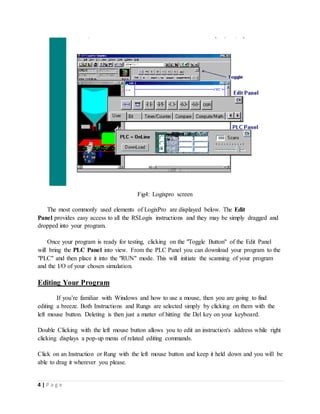
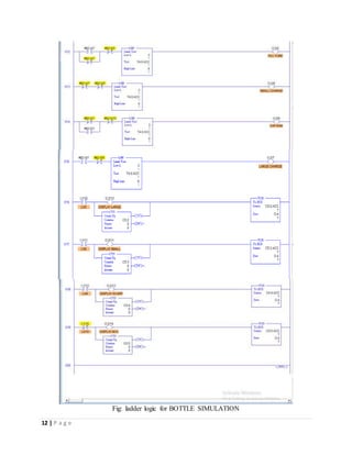
The document describes the development of a ladder logic program for a bottle line simulation using LogixPro software. It includes descriptions of the bottle line simulation process, inputs and outputs, conveyors, gates and sensors. The summary provides an overview of the key elements:
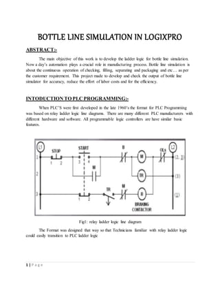
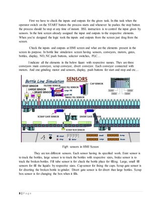
The document outlines the design of a ladder logic program to control a bottle line simulation involving checking, filling, separating and packaging bottles based on sensor inputs. It describes the LogixPro software used to create the ladder logic and emulate the PLC. The ladder logic is designed to track bottle properties using bit-shifting instructions, operate conveyors and gates based on sensor states, count bottles and boxes, and display production counts. The logic is meant to start and


![Lecture_26-27_PLC_Shi]dfsasadddddddddddddd](https://cdn.slidesharecdn.com/ss_thumbnails/lecture26-27plcshiftregisters-250721071803-04cccd2b-thumbnail.jpg?width=640&height=640&fit=bounds)


