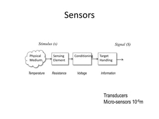
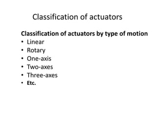
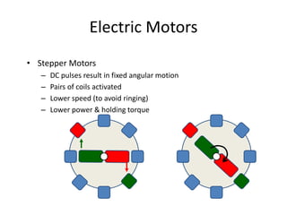
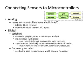
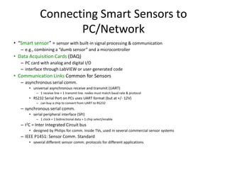
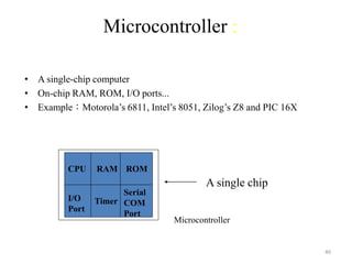
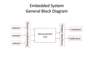
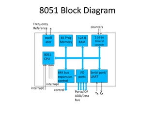
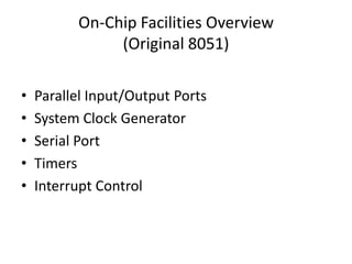
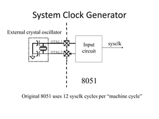
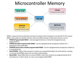
Sensors, Actuators and
Microcontrollers
Definitions
• Transducer
– a device that converts a primary form of energy into a corresponding
signal with a different energy form
• Primary Energy Forms: mechanical, thermal, electromagnetic, optical,
chemical, etc.
– take form of a sensor or an actuator
• Sensor (e.g., thermometer)
– a device that detects/measures a signal or stimulus
– acquires information from the “real world”
• Actuator (e.g., heater)
– a device that generates a signal or stimulus
real
world
sensor
actuator
intelligent
feedback
system
Sensor Systems
Typically interested in electronic sensor
– convert desired parameter into electrically measurable signal
• General Electronic Sensor
– primary transducer: changes “real world” parameter into electrical signal
– secondary transducer: converts electrical signal into analog or digital values
• Typical Electronic Sensor System
usable
values
real
world
analog
signal
primary
transducer
secondary
transducer
sensor
sensor
input
signal
(measurand)
microcontroller
signal processing
communication
sensor data
analog/digital
network
display
Computer-Process Interface
• To implement process control, the computer
must collect data from and transmit signals to
the production process
• Components required to implement the
interface:
– Sensors to measure continuous and discrete
process variables
– Actuators to drive continuous and discrete process
parameters
– Devices for ADC and DAC
– I/O devices for discrete data
Computer Process Control System
Actuators
Computer
Controller
Transformation Process
Sensors
DAC ADC
Input Devices
Output Devices
Continuous and Discrete
Variables
Continuous and Discrete
Parameters
Sensors
Physical
Medium
Sensing
Element
Conditioning Target
Handling
Temperature Resistance Voltage Information
Transducers
Micro-sensors 10-6m
Stimulus (s) Signal (S)
Transfer Function
where S = output signal; s = stimulus; and f(s) = functional relationship
For binary sensors: S = 1 if s > 0 and S = 0 if s < 0.
The ideal functional form for an analogue measuring device is a simple
proportional relationship, such as:
where C = output value at a stimulus value of zero
and m = constant of proportionality (sensitivity)
)
(s
f
S 
ms
C
S 

Example
• The output voltage of a particular
thermocouple sensor is registered to be 42.3
mV at temperature 105C. It had previously
been set to emit a zero voltage at 0C. Since
an output/input relationship exists between
the two temperatures, determine (1) the
transfer function of the thermocouple, and (2)
the temperature corresponding to a voltage
output of 15.8 mV.
Solution
42.3 mV = 0 + m(105C) = m(105C)
orm = 0.4028571429
S = 0.4 (s)
15.8 mV = 0.4 (s)
15.8 / 0.4 = s
s = 39.22C
ms
C
S 

Classes & Types of Sensors
• Four major classes of sensors:
– Tactile (contact - limit switches)
– Proximity & Range (non-contact)
– Vision (recognition, orientation)
– Miscellaneous (temp, pressure, strain)
• Two types of sensors:
– Analog (continuous physical quantity)
– Digital (discrete physical quantity)
Examples
• Position
– Limit switches
• ac/dc current
• location
– Potentiometers
• dc voltage
• angular / linear
– Resolvers
• ac voltage phase shift
• angular
– Encoders
• ac/dc current
• angular / linear location
• Incremental / Absolute
• Velocity
– Tachometer
• Analog
– dc voltage
– angular velocity
• Digital
– pulse frequency
– angular / linear velocity
• Temperature
• Capacitive
• Resistive
• Thermistors
• Pressure
• Piezo-electric
• Resistive
Examples
• Transducers
– ADCs -
• Analog to Digital Converters
– DACs -
• Digital to Analog Converters
– Frequency to Voltage
Converters
– Voltage to Frequency
Converters
• Analyzers
– Counters
– Timers
– Computers
– Ultra-Sonics
– Radar
• distance
• frequency shift
– Vision Systems
Contact and non-contact sensors
Contact sensor: a sensor that requires physical contact with
the stimulus. Examples: strain gauges, most temperature
sensors
Non-contact sensor: requires no physical contact. Examples:
most optical and magnetic sensors, infrared
thermometers, etc.
Absolute and relative sensors
Absolute sensor: a sensor that reacts to a stimulus on an
absolute scale: Thermistors, strain gauges, etc.,
(thermistor will always read the absolute temperature)
Relative scale: The stimulus is sensed relative to a fixed or
variable reference. Thermocouple measures the
temperature difference, pressure is often measured
relative to atmospheric pressure.
Other schemes
Classification by broad area of detection
• Electric sensors
• Magnetic
• Electromagnetic
• Acoustic
• Chemical
• Optical
• Heat, Temperature
• Mechanical
• Radiation
• Biological
• Etc.
Other schemes (cont.)
Classification by physical law
• Photoelectric
• Magnetoelectric
• Thermoelectric
• Photoconductive
• Magnitostrictive
• Electrostrictive
• Photomagnetic
• Thermoelastic
• Thermomagnetic
• Thermooptic
• Electrochermical
• Magnetoresistive
• Photoelastic
• Etc.
Other schemes (cont.)
Classification by specifications
• Accuracy
• Sensitivity
• Stability
• Response time
• Hysteresis
• Frequency response
• Input (stimulus) range
• Resolution
• Linearity
• Hardness (to environmental conditions, etc.)
• Cost
• Size, weight,
• Construction materials
• Operating temperature
• Etc.
Other schemes (cont.)
Classification by area of application
• Consumer products
• Military applications
• Infrastructure
• Energy
• Heat
• Manufacturing
• Transportation
• Automotive
• Avionic
• Marine
• Space
• Scientific
• Etc.
Primary Transducers
Transducer
• A device that converts energy of one form into energy of another
form.
• Conventional Transducers
large, but generally reliable, based on older technology
– thermocouple: temperature difference
– compass (magnetic): direction
• Microelectronic Sensors
millimeter sized, highly sensitive, less robust
– photodiode/phototransistor: photon energy (light)
• infrared detectors, proximity/intrusion alarms
– piezoresisitve pressure sensor: air/fluid pressure
– microaccelerometers: vibration, ∆-velocity (car crash)
– chemical sensors: O2, CO2, Cl, Nitrates (explosives)
– DNA arrays: match DNA sequences
Actuators
Hardware devices that convert a controller
command signal into a change in a physical
parameter
• The change is usually mechanical (e.g., position
or velocity)
• An actuator is also a transducer because it
changes one type of physical quantity into some
alternative form
• An actuator is usually activated by a low-level
command signal, so an amplifier may be required
to provide sufficient power to drive the actuator
Actuators
Signal Processing
& Amplification
Mechanism
Electric Hydraulic
Pneumatic
Final Actuation
Element
Actuator
Sensor
Logical
Signal
Classification of actuators
Classification of actuators by type of motion
• Linear
• Rotary
• One-axis
• Two-axes
• Three-axes
• Etc.
Types of Actuators
1. Electrical actuators
– Electric motors
• DC servomotors
• AC motors
• Stepper motors
– Solenoids
2. Hydraulic actuators
– Use hydraulic fluid to amplify the controller
command signal
3. Pneumatic actuators
– Use compressed air as the driving force
Actuators
• Linear Action: Stroke Length
– Cylinders:
• Hydraulic
– High force (1000 psi, typical)
– Low to medium speed
– Leaks, noise, bulk, cost
• Pneumatic
– Medium force (100 psi, typical)
– High speed
– Noise; intermediate mess, bulk & cost
– Solenoids (Electromagnetic):
– Low force (< 1 lbf, typical)
– Medium speed
– Quiet, clean, small, cheap
– Linear Slides (Electro-mechanical)
– Medium Force (50 – 400 lbf)
– Low to medium speed
– Quiet, clean, medium size & cost
Rotary Actuators (Drives)
• Rotary Action (may be converted to linear):
– Motors
• Hydraulic (rotary vanes)
– High power
– Low to medium speed, medium precision
– Leaks, noise, bulk, cost
• Pneumatic (rotary vanes)
– Medium power
– High speed, low precision
– Noise; intermediate mess, bulk & cost
• Electric
– Low power
– Medium speed, high precision
– Quiet, clean, small, cheap
Electric Motors
• Stepper Motors
– DC pulses result in fixed angular motion
– Pairs of coils activated
– Lower speed (to avoid ringing)
– Lower power & holding torque
Diff. Amp.
Electric Motors
• Servo Motors
– Require feedback to operate (tachometer)
– AC
• speed controlled by the frequency of the power supplied to the motor
• more powerful
– DC
• speed controlled by the magnitude of the voltage supplied to the motor
• holding torque
Velocity In
Feedback
Tachometer Motor
Shaft
+
–
Stepper motor and Servomotor
Motion Control
• Hard Automation
– Mechanical Cams:
• Shape of the cam determines motion of the follower
• “Reprogrammed” by changing out the cams
• Examples: Automatic screw machines, gun stocks
– Mechanical Stops:
• Range of motion is limited by stops
• “Reprogrammed” by changing the position of the stops
• Examples: Pneumatic “bang-bang robots”
Cam
Follower
Piston
Cylinder
Stops
Motion Control
• Point to Point
– Starting and ending points are given, but the path
between them is not controlled
– Advantage: simple, inexpensive controller
– Example: Peck drilling
Motion Control
• Continuous Path
– Both endpoints and the path between them are
controlled
– Advantage: complex shape capability
– Example: NC contouring
Connecting Sensors to Microcontrollers
• Analog
– many microcontrollers have a built-in A/D
• 8-bit to 12-bit common
• many have multi-channel A/D inputs
• Digital
– serial I/O
• use serial I/O port, store in memory to analyze
• synchronous (with clock)
– must match byte format, stop/start bits, parity check, etc.
• asynchronous (no clock): more common for comm. than data
– must match baud rate and bit width, transmission protocol, etc.
– frequency encoded
• use timing port, measure pulse width or pulse frequency
µC
signal timing
memory
keypad
sensor
sensor display
instrument
Connecting Smart Sensors to
PC/Network
• “Smart sensor” = sensor with built-in signal processing & communication
– e.g., combining a “dumb sensor” and a microcontroller
• Data Acquisition Cards (DAQ)
– PC card with analog and digital I/O
– interface through LabVIEW or user-generated code
• Communication Links Common for Sensors
– asynchronous serial comm.
• universal asynchronous receive and transmit (UART)
– 1 receive line + 1 transmit line. nodes must match baud rate & protocol
• RS232 Serial Port on PCs uses UART format (but at +/- 12V)
– can buy a chip to convert from UART to RS232
– synchronous serial comm.
• serial peripheral interface (SPI)
– 1 clock + 1 bidirectional data + 1 chip select/enable
– I2C = Inter Integrated Circuit bus
• designed by Philips for comm. inside TVs, used in several commercial sensor systems
– IEEE P1451: Sensor Comm. Standard
• several different sensor comm. protocols for different applications
Sensor Calibration
• Sensors can exhibit non-ideal effects
– offset: nominal output ≠ nominal parameter value
– nonlinearity: output not linear with parameter changes
– cross parameter sensitivity: secondary output variation with, e.g., temperature
• Calibration = adjusting output to match parameter
– analog signal conditioning
– look-up table
– digital calibration
• T = a + bV +cV2,
– T= temperature; V=sensor voltage;
– a,b,c = calibration coefficients
• Compensation
– remove secondary sensitivities
– must have sensitivities characterized
– can remove with polynomial evaluation
• P = a + bV + cT + dVT + e V2, where P=pressure, T=temperature
0.000
1.000
2.000
3.000
4.000
5.000
6.000
7.000
-30 -20 -10 0 10 20 30 40 50 60 70
Temperature (C)
Frequency
(MHz)
1001
1010
1001
1101
1110
1111
T1
T2
T3
offset
• An embedded microcontroller is a chip which
is a computer processor with all it’s support
functions (clocking and reset), memory, and
i/O built into the device.
Power dist
Control
store
Reset
control
Clock and
timing RAM
Microcontroller block diagram
Microcontrollers
CPU
Memory
Peripherals
3
6
PC vs Microcontroller
Microcontroller architecture
3
7
Comparing µC with µP
• General-purpose
microprocessors contains
o No RAM
o No ROM
o No I/O ports
• Microcontroller has
o CPU (microprocessor)
o RAM
o ROM
o I/O ports
o Timer
o ADC and other peripherals
 Have the advantage of versatility on the
amount of RAM, ROM, and I/O ports
 The fixed amount of on-chip ROM, RAM,
and number of I/O ports and less
computing power; suitable for very
specific purpose with much less cost.
39
CPU
General-
Purpose
Micro-
processor
RAM ROM I/O
Port
Timer
Serial
COM
Port
Data Bus
Address Bus
General-purpose microprocessor:
• CPU for Computers
• Commonly no RAM, ROM, I/O on CPU chip itself
Many chips on motherboard
40
RAM ROM
I/O
Port
Timer
Serial
COM
Port
Microcontroller
CPU
• A single-chip computer
• On-chip RAM, ROM, I/O ports...
• Example:Motorola’s 6811, Intel’s 8051, Zilog’s Z8 and PIC 16X
A single chip
Microcontroller :
41
Microprocessor
• CPU is stand-alone, RAM,
ROM, I/O, timer are separate
• designer can decide on the
amount of ROM, RAM and
I/O ports.
• expensive
• versatility
• general-purpose
• High processing power
• High power consumption
• Instruction sets focus on
processing-intensive
operations
• Typically 32/64 – bit
• Typically deep pipeline (5-20
stages)
Microcontroller
• CPU, RAM, ROM, I/O and timer
are all on a single chip
• fixed amount of on-chip ROM,
RAM, I/O ports
• for applications in which cost,
power and space are critical
• single-purpose (control-oriented)
• Low processing power
• Low power consumption
• Bit-level operations
• Instruction sets focus on control
and bit-level operations
• Typically 8/16 bit
• Typically single-cycle/two-stage
pipeline
Microprocessor vs. Microcontroller
Embedded System
General Block Diagram
Microcontroller
(uC)
sensor
sensor
sensor
Sensor
conditioning
Output
interfaces
actuator
indicator
Microcontroller Architectures
CPU
Program
+ Data
Address Bus
Data Bus
Memory
Von Neumann
Architecture
CPU
Program
Address Bus
Data Bus
Harvard
Architecture
Memory
Data
Address Bus
Fetch Bus
0
0
0
2n
Microcontroller Architectures
• CISC versus RISC
– RISC stands for “Reduced Instruction Set Computers”. Instructions are
as bare a minimum as possible to allow users to design their own
operations.
– CISC stands for “Complex Instruction Set Computers”. Large number of
instructions, each carrying out a different permutation of the same
operation.
– MCs with Harvard architecture are called "RISC MCs". MCs with
von-Neumann's architecture are called 'CISC microcontrollers'.
– Harvard architecture is a newer concept than von-Neumann's.
– In Harvard architecture, data bus and address bus are separate.
Thus a greater flow of data is possible through the CPU, and of
course, a greater speed of work.
Microcontroller Families
• Zilog Z8 series
• Arm 32 bit microcontrollers
• MicroChip – PIC microcontrollers
• Intel 8051 series The 8051 family has the largest
number of
diversified (multiple source) suppliers:
o Intel (original)
o Atmel
o Philips/Signetics
o AMD
o Infineon (formerly Siemens)
o Matra
o Dallas Semiconductor/Maxim
Common Microcontrollers
•Atmel
•ARM
•Intel
•8-bit
•8XC42
•MCS48
•MCS51
•8xC251
•16-bit
•MCS96
•MXS296
•National Semiconductor
•COP8
•Microchip
•12-bit instruction PIC
•14-bit instruction PIC
•PIC16F84
•16-bit instruction PIC
•NEC
•Motorola
•8-bit
•68HC05
•68HC08
•68HC11
•16-bit
•68HC12
•68HC16
•32-bit
•683xx
•Texas Instruments
•TMS370, 16/32 bit
•MSP430 , 16 bit
•Zilog
•Z8
•Z86E02
8051 µC features
• Intel introduced 8051, referred as MCS-51, in 1981
• The 8051 is an 8-bit processor
• The CPU can work on only 8 bits of data at a time
• 1 to 16 MHz clock
• The 8051 has
• 128 bytes of RAM
• 4K bytes of on-chip ROM
• Two timers
• One serial port
• Four I/O ports, each 8 bits wide
• 2 external and 3 internal interrupt sources
8051 µC features
• 8051 instruction cycle consists of 12 clock cycles.
• Application should be run using slower clock speed to reduce power
consumption.
• Dallas version of 8051 is 87C51 has EPROM as control store and CMOS
device:
• 24Mhz
• 12 cycle per instruction
• 4Kbyte of Control stote
• 128 bytes of RAM
• 32 I/O lines
• Two 8/16-bit times
• Multiple internal and external interrupts sources
• Programmable serial ports
• Interface upto 128Kbytes of external memory
8051 Block Diagram
oscill
ator
4K Prog
Memory
128 B
RAM
2 16-bit
timers/
counter
8051
CPU
64K bus
expansion
control
I/O
ports
Serial port/
UART
Frequency
Reference
interrupt
interrupt
control
Ports/IO/
ADD/Data
bus
Tx Rx
counters
On-Chip Facilities Overview
(Original 8051)
• Parallel Input/Output Ports
• System Clock Generator
• Serial Port
• Timers
• Interrupt Control
Parallel I/O Ports
Port0
latch
Port1
latch
Port2
latch
Port3
latch
Port0 Port1 Port2 Port3
• Each port can be input or output
• Direction is set in Special Function Registers (SFR)
System Clock Generator
Input
circuit
8051
sysclk
Original 8051 uses 12 sysclk cycles per “machine cycle”
External crystal oscillator
Serial Port
Universal Asynchronous Receiver-Transmitter (UART)
Serial
Port
TX (transmit)
RX (receive)
• Data sent and received serially
• BAUD rate must agree between sender and receiver
(The baud rate is a measure of the number of bits per second
that can be transmitted or received by the UART)
• Transmission modes selected using Special Function Register
(SFR)
Original 8051 had one serial port
Internal Timers
Original 8051 has 2 timers
16 bits
TH0 : TL0
Timer 0
16 bits
TH1 : TL1
Timer 1
Timers increment on each system clock
Timer registers (TH0, TL0, TH1, TL1) can be read or written to
Timer overflow can cause “interrupts” or set SFR bits high
Microcontroller Memory
ROM is a type of memory that does not lose its contents when the power is turned off. For this reason,
ROM is also called non volatile memory. There are different types of read-only memory, such as
• PROM (Programmable ROM) – Can be programmed once. Cannot be changed once you
programmed it.
• EPROM (Erasable Programmable ROM) – Can be reprogramed by erasing the content on it –
exposing to ultra-violet light.
• EEPROM (electrically erasable programmable ROM) - Can be reprogramed by erasing the content on
it using electricity.
• Flash EPROM - When Flash memory's contents are erased (electrically), the entire device is erased,
in contrast to EEPROM, where one can erase a desired byte.
• Mask ROM - Mask ROM refers to a kind of ROM in which the contents are programmed by the IC
manufacturer. In other words, it is not a user-programmable ROM.
Microcontroller alternatives
5
8
IR Object Detector
5
9
Sonar Object Detector
6
0

Chapter 2 - Sensors Actuators Microcontrollers.pptx

  • 1.
  • 2.
    Definitions • Transducer – adevice that converts a primary form of energy into a corresponding signal with a different energy form • Primary Energy Forms: mechanical, thermal, electromagnetic, optical, chemical, etc. – take form of a sensor or an actuator • Sensor (e.g., thermometer) – a device that detects/measures a signal or stimulus – acquires information from the “real world” • Actuator (e.g., heater) – a device that generates a signal or stimulus real world sensor actuator intelligent feedback system
  • 3.
    Sensor Systems Typically interestedin electronic sensor – convert desired parameter into electrically measurable signal • General Electronic Sensor – primary transducer: changes “real world” parameter into electrical signal – secondary transducer: converts electrical signal into analog or digital values • Typical Electronic Sensor System usable values real world analog signal primary transducer secondary transducer sensor sensor input signal (measurand) microcontroller signal processing communication sensor data analog/digital network display
  • 4.
    Computer-Process Interface • Toimplement process control, the computer must collect data from and transmit signals to the production process • Components required to implement the interface: – Sensors to measure continuous and discrete process variables – Actuators to drive continuous and discrete process parameters – Devices for ADC and DAC – I/O devices for discrete data
  • 5.
    Computer Process ControlSystem Actuators Computer Controller Transformation Process Sensors DAC ADC Input Devices Output Devices Continuous and Discrete Variables Continuous and Discrete Parameters
  • 6.
    Sensors Physical Medium Sensing Element Conditioning Target Handling Temperature ResistanceVoltage Information Transducers Micro-sensors 10-6m Stimulus (s) Signal (S)
  • 7.
    Transfer Function where S= output signal; s = stimulus; and f(s) = functional relationship For binary sensors: S = 1 if s > 0 and S = 0 if s < 0. The ideal functional form for an analogue measuring device is a simple proportional relationship, such as: where C = output value at a stimulus value of zero and m = constant of proportionality (sensitivity) ) (s f S  ms C S  
  • 8.
    Example • The outputvoltage of a particular thermocouple sensor is registered to be 42.3 mV at temperature 105C. It had previously been set to emit a zero voltage at 0C. Since an output/input relationship exists between the two temperatures, determine (1) the transfer function of the thermocouple, and (2) the temperature corresponding to a voltage output of 15.8 mV.
  • 9.
    Solution 42.3 mV =0 + m(105C) = m(105C) orm = 0.4028571429 S = 0.4 (s) 15.8 mV = 0.4 (s) 15.8 / 0.4 = s s = 39.22C ms C S  
  • 10.
    Classes & Typesof Sensors • Four major classes of sensors: – Tactile (contact - limit switches) – Proximity & Range (non-contact) – Vision (recognition, orientation) – Miscellaneous (temp, pressure, strain) • Two types of sensors: – Analog (continuous physical quantity) – Digital (discrete physical quantity)
  • 11.
    Examples • Position – Limitswitches • ac/dc current • location – Potentiometers • dc voltage • angular / linear – Resolvers • ac voltage phase shift • angular – Encoders • ac/dc current • angular / linear location • Incremental / Absolute • Velocity – Tachometer • Analog – dc voltage – angular velocity • Digital – pulse frequency – angular / linear velocity • Temperature • Capacitive • Resistive • Thermistors • Pressure • Piezo-electric • Resistive
  • 12.
    Examples • Transducers – ADCs- • Analog to Digital Converters – DACs - • Digital to Analog Converters – Frequency to Voltage Converters – Voltage to Frequency Converters • Analyzers – Counters – Timers – Computers – Ultra-Sonics – Radar • distance • frequency shift – Vision Systems
  • 13.
    Contact and non-contactsensors Contact sensor: a sensor that requires physical contact with the stimulus. Examples: strain gauges, most temperature sensors Non-contact sensor: requires no physical contact. Examples: most optical and magnetic sensors, infrared thermometers, etc.
  • 14.
    Absolute and relativesensors Absolute sensor: a sensor that reacts to a stimulus on an absolute scale: Thermistors, strain gauges, etc., (thermistor will always read the absolute temperature) Relative scale: The stimulus is sensed relative to a fixed or variable reference. Thermocouple measures the temperature difference, pressure is often measured relative to atmospheric pressure.
  • 15.
    Other schemes Classification bybroad area of detection • Electric sensors • Magnetic • Electromagnetic • Acoustic • Chemical • Optical • Heat, Temperature • Mechanical • Radiation • Biological • Etc.
  • 16.
    Other schemes (cont.) Classificationby physical law • Photoelectric • Magnetoelectric • Thermoelectric • Photoconductive • Magnitostrictive • Electrostrictive • Photomagnetic • Thermoelastic • Thermomagnetic • Thermooptic • Electrochermical • Magnetoresistive • Photoelastic • Etc.
  • 17.
    Other schemes (cont.) Classificationby specifications • Accuracy • Sensitivity • Stability • Response time • Hysteresis • Frequency response • Input (stimulus) range • Resolution • Linearity • Hardness (to environmental conditions, etc.) • Cost • Size, weight, • Construction materials • Operating temperature • Etc.
  • 18.
    Other schemes (cont.) Classificationby area of application • Consumer products • Military applications • Infrastructure • Energy • Heat • Manufacturing • Transportation • Automotive • Avionic • Marine • Space • Scientific • Etc.
  • 19.
    Primary Transducers Transducer • Adevice that converts energy of one form into energy of another form. • Conventional Transducers large, but generally reliable, based on older technology – thermocouple: temperature difference – compass (magnetic): direction • Microelectronic Sensors millimeter sized, highly sensitive, less robust – photodiode/phototransistor: photon energy (light) • infrared detectors, proximity/intrusion alarms – piezoresisitve pressure sensor: air/fluid pressure – microaccelerometers: vibration, ∆-velocity (car crash) – chemical sensors: O2, CO2, Cl, Nitrates (explosives) – DNA arrays: match DNA sequences
  • 20.
    Actuators Hardware devices thatconvert a controller command signal into a change in a physical parameter • The change is usually mechanical (e.g., position or velocity) • An actuator is also a transducer because it changes one type of physical quantity into some alternative form • An actuator is usually activated by a low-level command signal, so an amplifier may be required to provide sufficient power to drive the actuator
  • 21.
    Actuators Signal Processing & Amplification Mechanism ElectricHydraulic Pneumatic Final Actuation Element Actuator Sensor Logical Signal
  • 22.
    Classification of actuators Classificationof actuators by type of motion • Linear • Rotary • One-axis • Two-axes • Three-axes • Etc.
  • 23.
    Types of Actuators 1.Electrical actuators – Electric motors • DC servomotors • AC motors • Stepper motors – Solenoids 2. Hydraulic actuators – Use hydraulic fluid to amplify the controller command signal 3. Pneumatic actuators – Use compressed air as the driving force
  • 24.
    Actuators • Linear Action:Stroke Length – Cylinders: • Hydraulic – High force (1000 psi, typical) – Low to medium speed – Leaks, noise, bulk, cost • Pneumatic – Medium force (100 psi, typical) – High speed – Noise; intermediate mess, bulk & cost – Solenoids (Electromagnetic): – Low force (< 1 lbf, typical) – Medium speed – Quiet, clean, small, cheap – Linear Slides (Electro-mechanical) – Medium Force (50 – 400 lbf) – Low to medium speed – Quiet, clean, medium size & cost
  • 25.
    Rotary Actuators (Drives) •Rotary Action (may be converted to linear): – Motors • Hydraulic (rotary vanes) – High power – Low to medium speed, medium precision – Leaks, noise, bulk, cost • Pneumatic (rotary vanes) – Medium power – High speed, low precision – Noise; intermediate mess, bulk & cost • Electric – Low power – Medium speed, high precision – Quiet, clean, small, cheap
  • 26.
    Electric Motors • StepperMotors – DC pulses result in fixed angular motion – Pairs of coils activated – Lower speed (to avoid ringing) – Lower power & holding torque
  • 27.
    Diff. Amp. Electric Motors •Servo Motors – Require feedback to operate (tachometer) – AC • speed controlled by the frequency of the power supplied to the motor • more powerful – DC • speed controlled by the magnitude of the voltage supplied to the motor • holding torque Velocity In Feedback Tachometer Motor Shaft + –
  • 28.
  • 29.
    Motion Control • HardAutomation – Mechanical Cams: • Shape of the cam determines motion of the follower • “Reprogrammed” by changing out the cams • Examples: Automatic screw machines, gun stocks – Mechanical Stops: • Range of motion is limited by stops • “Reprogrammed” by changing the position of the stops • Examples: Pneumatic “bang-bang robots” Cam Follower Piston Cylinder Stops
  • 30.
    Motion Control • Pointto Point – Starting and ending points are given, but the path between them is not controlled – Advantage: simple, inexpensive controller – Example: Peck drilling
  • 31.
    Motion Control • ContinuousPath – Both endpoints and the path between them are controlled – Advantage: complex shape capability – Example: NC contouring
  • 32.
    Connecting Sensors toMicrocontrollers • Analog – many microcontrollers have a built-in A/D • 8-bit to 12-bit common • many have multi-channel A/D inputs • Digital – serial I/O • use serial I/O port, store in memory to analyze • synchronous (with clock) – must match byte format, stop/start bits, parity check, etc. • asynchronous (no clock): more common for comm. than data – must match baud rate and bit width, transmission protocol, etc. – frequency encoded • use timing port, measure pulse width or pulse frequency µC signal timing memory keypad sensor sensor display instrument
  • 33.
    Connecting Smart Sensorsto PC/Network • “Smart sensor” = sensor with built-in signal processing & communication – e.g., combining a “dumb sensor” and a microcontroller • Data Acquisition Cards (DAQ) – PC card with analog and digital I/O – interface through LabVIEW or user-generated code • Communication Links Common for Sensors – asynchronous serial comm. • universal asynchronous receive and transmit (UART) – 1 receive line + 1 transmit line. nodes must match baud rate & protocol • RS232 Serial Port on PCs uses UART format (but at +/- 12V) – can buy a chip to convert from UART to RS232 – synchronous serial comm. • serial peripheral interface (SPI) – 1 clock + 1 bidirectional data + 1 chip select/enable – I2C = Inter Integrated Circuit bus • designed by Philips for comm. inside TVs, used in several commercial sensor systems – IEEE P1451: Sensor Comm. Standard • several different sensor comm. protocols for different applications
  • 34.
    Sensor Calibration • Sensorscan exhibit non-ideal effects – offset: nominal output ≠ nominal parameter value – nonlinearity: output not linear with parameter changes – cross parameter sensitivity: secondary output variation with, e.g., temperature • Calibration = adjusting output to match parameter – analog signal conditioning – look-up table – digital calibration • T = a + bV +cV2, – T= temperature; V=sensor voltage; – a,b,c = calibration coefficients • Compensation – remove secondary sensitivities – must have sensitivities characterized – can remove with polynomial evaluation • P = a + bV + cT + dVT + e V2, where P=pressure, T=temperature 0.000 1.000 2.000 3.000 4.000 5.000 6.000 7.000 -30 -20 -10 0 10 20 30 40 50 60 70 Temperature (C) Frequency (MHz) 1001 1010 1001 1101 1110 1111 T1 T2 T3 offset
  • 35.
    • An embeddedmicrocontroller is a chip which is a computer processor with all it’s support functions (clocking and reset), memory, and i/O built into the device. Power dist Control store Reset control Clock and timing RAM Microcontroller block diagram Microcontrollers
  • 36.
  • 37.
  • 38.
    Comparing µC withµP • General-purpose microprocessors contains o No RAM o No ROM o No I/O ports • Microcontroller has o CPU (microprocessor) o RAM o ROM o I/O ports o Timer o ADC and other peripherals  Have the advantage of versatility on the amount of RAM, ROM, and I/O ports  The fixed amount of on-chip ROM, RAM, and number of I/O ports and less computing power; suitable for very specific purpose with much less cost.
  • 39.
    39 CPU General- Purpose Micro- processor RAM ROM I/O Port Timer Serial COM Port DataBus Address Bus General-purpose microprocessor: • CPU for Computers • Commonly no RAM, ROM, I/O on CPU chip itself Many chips on motherboard
  • 40.
    40 RAM ROM I/O Port Timer Serial COM Port Microcontroller CPU • Asingle-chip computer • On-chip RAM, ROM, I/O ports... • Example:Motorola’s 6811, Intel’s 8051, Zilog’s Z8 and PIC 16X A single chip Microcontroller :
  • 41.
    41 Microprocessor • CPU isstand-alone, RAM, ROM, I/O, timer are separate • designer can decide on the amount of ROM, RAM and I/O ports. • expensive • versatility • general-purpose • High processing power • High power consumption • Instruction sets focus on processing-intensive operations • Typically 32/64 – bit • Typically deep pipeline (5-20 stages) Microcontroller • CPU, RAM, ROM, I/O and timer are all on a single chip • fixed amount of on-chip ROM, RAM, I/O ports • for applications in which cost, power and space are critical • single-purpose (control-oriented) • Low processing power • Low power consumption • Bit-level operations • Instruction sets focus on control and bit-level operations • Typically 8/16 bit • Typically single-cycle/two-stage pipeline Microprocessor vs. Microcontroller
  • 42.
    Embedded System General BlockDiagram Microcontroller (uC) sensor sensor sensor Sensor conditioning Output interfaces actuator indicator
  • 43.
    Microcontroller Architectures CPU Program + Data AddressBus Data Bus Memory Von Neumann Architecture CPU Program Address Bus Data Bus Harvard Architecture Memory Data Address Bus Fetch Bus 0 0 0 2n
  • 44.
  • 45.
    Microcontroller Architectures • CISCversus RISC – RISC stands for “Reduced Instruction Set Computers”. Instructions are as bare a minimum as possible to allow users to design their own operations. – CISC stands for “Complex Instruction Set Computers”. Large number of instructions, each carrying out a different permutation of the same operation. – MCs with Harvard architecture are called "RISC MCs". MCs with von-Neumann's architecture are called 'CISC microcontrollers'. – Harvard architecture is a newer concept than von-Neumann's. – In Harvard architecture, data bus and address bus are separate. Thus a greater flow of data is possible through the CPU, and of course, a greater speed of work.
  • 46.
    Microcontroller Families • ZilogZ8 series • Arm 32 bit microcontrollers • MicroChip – PIC microcontrollers • Intel 8051 series The 8051 family has the largest number of diversified (multiple source) suppliers: o Intel (original) o Atmel o Philips/Signetics o AMD o Infineon (formerly Siemens) o Matra o Dallas Semiconductor/Maxim
  • 47.
    Common Microcontrollers •Atmel •ARM •Intel •8-bit •8XC42 •MCS48 •MCS51 •8xC251 •16-bit •MCS96 •MXS296 •National Semiconductor •COP8 •Microchip •12-bitinstruction PIC •14-bit instruction PIC •PIC16F84 •16-bit instruction PIC •NEC •Motorola •8-bit •68HC05 •68HC08 •68HC11 •16-bit •68HC12 •68HC16 •32-bit •683xx •Texas Instruments •TMS370, 16/32 bit •MSP430 , 16 bit •Zilog •Z8 •Z86E02
  • 48.
    8051 µC features •Intel introduced 8051, referred as MCS-51, in 1981 • The 8051 is an 8-bit processor • The CPU can work on only 8 bits of data at a time • 1 to 16 MHz clock • The 8051 has • 128 bytes of RAM • 4K bytes of on-chip ROM • Two timers • One serial port • Four I/O ports, each 8 bits wide • 2 external and 3 internal interrupt sources
  • 49.
    8051 µC features •8051 instruction cycle consists of 12 clock cycles. • Application should be run using slower clock speed to reduce power consumption. • Dallas version of 8051 is 87C51 has EPROM as control store and CMOS device: • 24Mhz • 12 cycle per instruction • 4Kbyte of Control stote • 128 bytes of RAM • 32 I/O lines • Two 8/16-bit times • Multiple internal and external interrupts sources • Programmable serial ports • Interface upto 128Kbytes of external memory
  • 50.
    8051 Block Diagram oscill ator 4KProg Memory 128 B RAM 2 16-bit timers/ counter 8051 CPU 64K bus expansion control I/O ports Serial port/ UART Frequency Reference interrupt interrupt control Ports/IO/ ADD/Data bus Tx Rx counters
  • 52.
    On-Chip Facilities Overview (Original8051) • Parallel Input/Output Ports • System Clock Generator • Serial Port • Timers • Interrupt Control
  • 53.
    Parallel I/O Ports Port0 latch Port1 latch Port2 latch Port3 latch Port0Port1 Port2 Port3 • Each port can be input or output • Direction is set in Special Function Registers (SFR)
  • 54.
    System Clock Generator Input circuit 8051 sysclk Original8051 uses 12 sysclk cycles per “machine cycle” External crystal oscillator
  • 55.
    Serial Port Universal AsynchronousReceiver-Transmitter (UART) Serial Port TX (transmit) RX (receive) • Data sent and received serially • BAUD rate must agree between sender and receiver (The baud rate is a measure of the number of bits per second that can be transmitted or received by the UART) • Transmission modes selected using Special Function Register (SFR) Original 8051 had one serial port
  • 56.
    Internal Timers Original 8051has 2 timers 16 bits TH0 : TL0 Timer 0 16 bits TH1 : TL1 Timer 1 Timers increment on each system clock Timer registers (TH0, TL0, TH1, TL1) can be read or written to Timer overflow can cause “interrupts” or set SFR bits high
  • 57.
    Microcontroller Memory ROM isa type of memory that does not lose its contents when the power is turned off. For this reason, ROM is also called non volatile memory. There are different types of read-only memory, such as • PROM (Programmable ROM) – Can be programmed once. Cannot be changed once you programmed it. • EPROM (Erasable Programmable ROM) – Can be reprogramed by erasing the content on it – exposing to ultra-violet light. • EEPROM (electrically erasable programmable ROM) - Can be reprogramed by erasing the content on it using electricity. • Flash EPROM - When Flash memory's contents are erased (electrically), the entire device is erased, in contrast to EEPROM, where one can erase a desired byte. • Mask ROM - Mask ROM refers to a kind of ROM in which the contents are programmed by the IC manufacturer. In other words, it is not a user-programmable ROM.
  • 58.
  • 59.
  • 60.