Kinematic performance analysis of 4 link planar serial manipulatoreSAT Journals
Abstract This investigation is all about determining condition number for four link planner serial manipulator. Condition number which measures the accuracy of end effector velocity is obtained from the Jacobian matrix of the four link planner serial manipulator. Inverse of a non-square matrix in the calculation of the condition number. Pseudo inverse procedure is used for the calculation of inverse of jacobian matrix using condition number. Isotropic condition for manipulator is found. “MAT Lab” 6.1.0 version is used to determine the condition number which is recently developed for complex matrix manipulations. A computer program in “MAT Lab” is written for finding Jocobian matrix, inverse of Jacobian matrix, norm of jacobian and norm of Jacobian matrix and the condition number for various input joint angles and link lengths. Keywords: Serial manipulator, Condition number, Jacobian matrix, MAT Lab,
Wall follower autonomous robot development applying fuzzy incremental controllerrajabco
This paper presents the design of an autonomous robot as a basic development of an intelligent wheeled mobile robot for air duct or corridor cleaning. The robot navigation is based on wall following algorithm. The robot is controlled us- ing fuzzy incremental controller (FIC) and embedded in PIC18F4550 microcontroller. FIC guides the robot to move along a wall in a desired direction by maintaining a constant distance to the wall. Two ultrasonic sensors are installed in the left side of the robot to sense the wall distance. The signals from these sensors are fed to FIC that then used to de- termine the speed control of two DC motors. The robot movement is obtained through differentiating the speed of these two motors. The experimental results show that FIC is successfully controlling the robot to follow the wall as a guid- ance line and has good performance compare with PID controller.
Final Project - Designing Mechatronic Systems for Rehabilitation.
With the progressively ageing of the population, the proportion of elders is strongly increasing. Linked to this stage of life are the many physical impairments that arise due to an increased frailty caused by disease or simply by the wear of body parts. In the following pages, we will study some of the most important organs and systems associated with balance maintenance. And, when not working properly, they may lead to injury or premature deaths.
Sorbonne Université - 5th Year - 1st Semester - Mechatronic Systems for Rehabilitation.
Insect inspired hexapod robot for terrain navigationeSAT Journals
Abstract The aim of this paper is to build a sixlegged walking robot that is capable of basicmobility tasks such as walking forward, backward, rotating in place and raising orlowering the body height. The legs will be of a modular design and will have threedegrees of freedom each. This robot will serve as a platform onto which additionalsensory components could be added, or which could be programmed to performincreasingly complex motions. This report discusses the components that make up ourfinal design.In this paper we have selected ahexapod robot; we are focusing &developingmainly on efficient navigation method indifferent terrain using opposite gait of locomotion, which will make it faster and at sametime energy efficient to navigate and negotiate difficult terrain.This paper discuss the Features, development, and implementation of the Hexapod robot Index Terms:Biologically inspired, Gait Generation,Legged hexapod, Navigation.
Stabilization of Six-Legged Robot on Tilt Surface With 9 DOF IMU Based on Inv...IJRES Journal
Robot is a tool which is developed very fast. There are several types of robots, one of them is six-legged robot. One of the problems of this robot is when the robot walks on the tilt surface. This would result the movement of the robot could be late and the center of gravity is not balanced. In this research, stabilization of six-legged robot walking on tilt surface using nine degree of freedom (DOF) inertial measurement unit (IMU) sensor based on invers kinematic is designed. The IMU sensor comprises a gyroscope, a magnetometer, and three-axis accelerometer. This sensor works as the input of the tilt degree and heading of the robot, therefore they can be processed in fuzzy-pid controller to balance the body of the robot on tilt surface. The results show that the robot will move forward when the x-axis translation inverse changed from its original position, move aside when the y-axis translational modified and move up and down if the translation to the z-axis was changed. From the testing of IMU get the total of RMSE pitch is 1,73%, roll =1,67% and yaw = 1,24%. In controller fuzzy-pid get the good respon is on the value Kp have k1=0,5, k2=1 , k3 = 3 , Ki have k1=0,5 , k2=0,5, k3=0,5 and Kd have k1=0,25 , k2=0,35 dan k3=0,45.
Motion Control of Differential Wheeled Robots with Joint Limit Constraints (S...obijuan_cube
The motion of wheeled mobile robots is inherently based on their wheels' rolling capabilities. The assumption is that each wheel can rotate indefinitely, backwards or forward. This is the starting point for all motion control mechanisms of wheeled robots. In this paper, a new motion capability of differential mobile robots with limited wheel rotation capabilities is presented. The robot will be able to travel any distance and change its direction of movement even if its wheels can not rotate within more than a certain range of angles. The proposed solution is based on the bio-inspired controller principles used for modular and legged robots, in which oscillations are generated for achieving motion. A total of two oscillators, one per wheel, are enough to generate well-coordinated rhythms on the wheels to control the robot motion. The kinematics of this new type of mobile robot motion is presented, and the relation between the oscillator's parameters and the trajectory is studied. Experiments with real robots will demonstrate the viability of this new locomotion gait.
IJRET : International Journal of Research in Engineering and Technology is an international peer reviewed, online journal published by eSAT Publishing House for the enhancement of research in various disciplines of Engineering and Technology. The aim and scope of the journal is to provide an academic medium and an important reference for the advancement and dissemination of research results that support high-level learning, teaching and research in the fields of Engineering and Technology. We bring together Scientists, Academician, Field Engineers, Scholars and Students of related fields of Engineering and Technology.
Maze solving problem is a very old problem, but still now it is considered as an important field of robotics. This field is based on decision making algorithms. The main aim of this project is to make an Arduino based efficient autonomous maze solver robot. Two simple mazes solving algorithms “Wall following algorithm” and “Flood fill algorithm” are used to make this robot. In this project Hardware development, software development and maze construction had been done. For performance testing, the robot will implement to solve 4×4 maze. Capability of finding the shortest path is also verified.
-- Musfiqur Rahman; email: musfiqur.rahman.ete@ulab.edu.bd
This presentation describe about the robots, their history and different types of robots used at different places. It will give you a basic concept and analysis of Robots configuration and Laws.
This paper presents the design of an autonomous robot as a basic development of an intelligent wheeled mobile robot for air duct or corridor cleaning. The robot navigation is based on wall following algorithm. The robot is controlled us- ing fuzzy incremental controller (FIC) and embedded in PIC18F4550 microcontroller. FIC guides the robot to move along a wall in a desired direction by maintaining a constant distance to the wall. Two ultrasonic sensors are installed in the left side of the robot to sense the wall distance. The signals from these sensors are fed to FIC that then used to determine the speed control of two DC motors. The robot movement is obtained through differentiating the speed of these two motors. The experimental results show that FIC is successfully controlling the robot to follow the wall as a guidance line and has good performance compare with PID controller.
Introduction to robotics, Laws,Classification,Types, Drives,Geometry Mohammad Ehtasham
Introduction to robotics , Basic overview ,Classification of robotics,laws of robotics,Types of robot, Robot Geometry, Robot drives, Some of the key benefits of robots in industry and society
Fire Detector and Extinguisher Robot is operated to detect the fire and also to extinguish it. It can be operated in two modes one is manual mode and other is autonomous mode. Manual mode is operated using joysticks and for autonomous mode there is no human intervention. In manual mode direction of the robot is controlled using joysticks, even pump is operated manually. In autonomous mode IR sensors are used to detect the fire and robot is coded accordingly to move in the direction of detected fire. In this robot has a switch which is used to switch between manual and autonomous mode.
We all have good and bad thoughts from time to time and situation to situation. We are bombarded daily with spiraling thoughts(both negative and positive) creating all-consuming feel , making us difficult to manage with associated suffering. Good thoughts are like our Mob Signal (Positive thought) amidst noise(negative thought) in the atmosphere. Negative thoughts like noise outweigh positive thoughts. These thoughts often create unwanted confusion, trouble, stress and frustration in our mind as well as chaos in our physical world. Negative thoughts are also known as “distorted thinking”.
Palestine last event orientationfvgnh .pptxRaedMohamed3
An EFL lesson about the current events in Palestine. It is intended to be for intermediate students who wish to increase their listening skills through a short lesson in power point.
How to Create Map Views in the Odoo 17 ERPCeline George
The map views are useful for providing a geographical representation of data. They allow users to visualize and analyze the data in a more intuitive manner.
Read| The latest issue of The Challenger is here! We are thrilled to announce that our school paper has qualified for the NATIONAL SCHOOLS PRESS CONFERENCE (NSPC) 2024. Thank you for your unwavering support and trust. Dive into the stories that made us stand out!
Ethnobotany and Ethnopharmacology:
Ethnobotany in herbal drug evaluation,
Impact of Ethnobotany in traditional medicine,
New development in herbals,
Bio-prospecting tools for drug discovery,
Role of Ethnopharmacology in drug evaluation,
Reverse Pharmacology.
2024.06.01 Introducing a competency framework for languag learning materials ...Sandy Millin
http://sandymillin.wordpress.com/iateflwebinar2024
Published classroom materials form the basis of syllabuses, drive teacher professional development, and have a potentially huge influence on learners, teachers and education systems. All teachers also create their own materials, whether a few sentences on a blackboard, a highly-structured fully-realised online course, or anything in between. Despite this, the knowledge and skills needed to create effective language learning materials are rarely part of teacher training, and are mostly learnt by trial and error.
Knowledge and skills frameworks, generally called competency frameworks, for ELT teachers, trainers and managers have existed for a few years now. However, until I created one for my MA dissertation, there wasn’t one drawing together what we need to know and do to be able to effectively produce language learning materials.
This webinar will introduce you to my framework, highlighting the key competencies I identified from my research. It will also show how anybody involved in language teaching (any language, not just English!), teacher training, managing schools or developing language learning materials can benefit from using the framework.
Unit 8 - Information and Communication Technology (Paper I).pdfThiyagu K
This slides describes the basic concepts of ICT, basics of Email, Emerging Technology and Digital Initiatives in Education. This presentations aligns with the UGC Paper I syllabus.
The Roman Empire A Historical Colossus.pdfkaushalkr1407
The Roman Empire, a vast and enduring power, stands as one of history's most remarkable civilizations, leaving an indelible imprint on the world. It emerged from the Roman Republic, transitioning into an imperial powerhouse under the leadership of Augustus Caesar in 27 BCE. This transformation marked the beginning of an era defined by unprecedented territorial expansion, architectural marvels, and profound cultural influence.
The empire's roots lie in the city of Rome, founded, according to legend, by Romulus in 753 BCE. Over centuries, Rome evolved from a small settlement to a formidable republic, characterized by a complex political system with elected officials and checks on power. However, internal strife, class conflicts, and military ambitions paved the way for the end of the Republic. Julius Caesar’s dictatorship and subsequent assassination in 44 BCE created a power vacuum, leading to a civil war. Octavian, later Augustus, emerged victorious, heralding the Roman Empire’s birth.
Under Augustus, the empire experienced the Pax Romana, a 200-year period of relative peace and stability. Augustus reformed the military, established efficient administrative systems, and initiated grand construction projects. The empire's borders expanded, encompassing territories from Britain to Egypt and from Spain to the Euphrates. Roman legions, renowned for their discipline and engineering prowess, secured and maintained these vast territories, building roads, fortifications, and cities that facilitated control and integration.
The Roman Empire’s society was hierarchical, with a rigid class system. At the top were the patricians, wealthy elites who held significant political power. Below them were the plebeians, free citizens with limited political influence, and the vast numbers of slaves who formed the backbone of the economy. The family unit was central, governed by the paterfamilias, the male head who held absolute authority.
Culturally, the Romans were eclectic, absorbing and adapting elements from the civilizations they encountered, particularly the Greeks. Roman art, literature, and philosophy reflected this synthesis, creating a rich cultural tapestry. Latin, the Roman language, became the lingua franca of the Western world, influencing numerous modern languages.
Roman architecture and engineering achievements were monumental. They perfected the arch, vault, and dome, constructing enduring structures like the Colosseum, Pantheon, and aqueducts. These engineering marvels not only showcased Roman ingenuity but also served practical purposes, from public entertainment to water supply.
1. Chapter 2
Robot Mechanisms, Sensors and Actuators
2.1 Robot Mechanisms
A robot is a machine capable of physical motion for interacting with the environment. Physical
interactions include manipulation, locomotion, and any other tasks changing the state of the
environment or the state of the robot relative to the environment. A robot has some form of
mechanisms for performing a class of tasks. A rich variety of robot mechanisms has been
developed in the last few decades. In this chapter, we will first overview various types of
mechanisms used for generating robotic motion, and introduce some taxonomy of mechanical
structures before going into a more detailed analysis in the subsequent chapters.
2.1.1 Joint Primitives and Serial Linkages
A robot mechanism is a multi-body system with the multiple bodies connected together. We
begin by treating each body as rigid, ignoring elasticity and any deformations caused by large
load conditions. Each rigid body involved in a robot mechanism is called a link, and a
combination of links is referred to as a linkage. In describing a linkage it is fundamental to
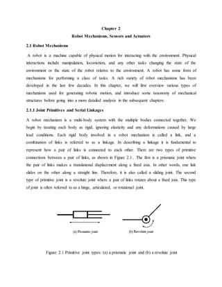
represent how a pair of links is connected to each other. There are two types of primitive
connections between a pair of links, as shown in Figure 2.1.. The first is a prismatic joint where
the pair of links makes a translational displacement along a fixed axis. In other words, one link
slides on the other along a straight line. Therefore, it is also called a sliding joint. The second
type of primitive joint is a revolute joint where a pair of links rotates about a fixed axis. This type
of joint is often referred to as a hinge, articulated, or rotational joint.
Figure 2.1 Primitive joint types: (a) a prismatic joint and (b) a revolute joint
2. Combining these two types of primitive joints, we can create many useful mechanisms for robot
manipulation and locomotion. These two types of primitive joints are simple to build and are
well grounded in engineering design. Most of the robots that have been built are combinations of
only these two types. Let us look at some examples.
Robot mechanisms analogous to coordinate systems: One of the fundamental functional
requirements for a robotic system is to locate its end-effecter, e.g. a hand, a leg, or any other part
of the body performing a task, in three-dimensional space. If the kinematic structure of such a
robot mechanism is analogous to a coordinate system, it may suffice this positioning
requirement. Figures 2.2 show three types of robot arm structures corresponding to the Cartesian
coordinate system, the cylindrical coordinate system, and the spherical coordinate system
respectively. The Cartesian coordinate robot shown in Figure 2.2 has three prismatic joints,
corresponding to three axes denoted x, y, and z. The cylindrical robot consists of one revolute
joint and two prismatic joints, with r, and z representing the coordinates of the end-effecter.
Likewise, the spherical robot has two revolute joints denoted and one prismatic joint denoted r.
Figure 2.2 Cartesian coordinate robot
There are many other ways of locating an end-effecter in three-dimensional space. Figure 2.3
show three other kinematic structures that allow the robot to locate its end-effecter in three-
dimensional space. Although these mechanisms have no analogy with common coordinate
systems, they are capable of locating the end-effecter in space, and have salient features desirable
3. for specific tasks. The first one is a so-called SCALAR robot consisting of two revolute joints
and one prismatic joint. This robot structure is particularly desirable for assembly automation in
manufacturing systems, having a wide workspace in the horizontal direction and an independent
vertical axis appropriate for insertion of parts.
Figure 2.3 SCALAR type robot.
The second type, called an articulated robot or an elbow robot, consists of all three revolute
joints, like a human arm. This type of robot has a great degree of flexibility and versatility, being
the most standard structure of robot manipulators. The third kinematic structure, also consisting
of three revolute joints, has a unique mass balancing structure. The counter balance at the elbow
eliminates gravity load for all three joints, thus reducing toque requirements for the actuators.
This structure has been used for the direct-drive robots having no gear reducer.
Figure 2.4 Articulated robot
4. Note that all the above robot structures are made of serial connections of primitive joints. This
class of kinematic structures, termed a serial linkage, constitutes the fundamental makeup of
robot mechanisms. They have no kinematic constraint in each joint motion, i.e. each joint
displacement is a generalized coordinate. This facilitates the analysis and control of the robot
mechanism. There are, however, different classes of mechanisms used for robot structures.
Although more complex, they do provide some useful properties. We will look at these other
mechanisms in the subsequent sections.
3.2 Parallel Linkages
Primitive joints can be arranged in parallel as well as in series. Figure 2.5 illustrates such a
parallel link mechanism. It is a five-bar-linkage consisting of five links, including the base link,
connected by five joints. This can be viewed as two serial linkage arms connected at a particular
point, point A in the figure. It is important to note that there is a closed kinematic chain formed
by the five links and, thereby, the two serial link arms must conform to a certain geometric
constraint. It is clear from the figure that the end-effecter position is determined if two of the five
joint angles are given. For example, if angles 1? and 3? of joints 1 and 3 are determined, then all
the link positions are determined, as is the end-effecter’s. Driving joints 1 and 3 with two
actuators, we can move the end-effecter within the vertical plane. It should be noted that, if more
than two joints were actively driven by independent actuators, a conflict among three actuators
would occur due to the closed-loop kinematic chain. Three of the five joints should be passive
joints, which are free to rotate. Only two joints should be active joints, driven by independent
actuators.
5. Figure 2.5 Five-bar-link parallel link robot
This type of parallel linkage, having a closed-loop kinematic chain, has significant features.
First, placing both actuators at the base link makes the robot arm lighter, compared to the serial
link arm with the second motor fixed to the tip of link 1. Second, a larger end-effecter load can
be born with the two serial linkage arms sharing the load.
Figure 2.6 shows the Stewart mechanism, which consists of a moving platform, a fixed base, and
six powered cylinders connecting the moving platform to the base frame. The position and
orientation of the moving platform are determined by the six independent actuators. The load
acting on the moving platform is born by the six "arms". Therefore, the load capacity is generally
large, and dynamic response is fast for this type of robot mechanisms. Note, however, that this
mechanism has spherical joints, a different type of joints than the primitive joints we considered
initially.
6. Figure 2.6 Stewart mechanism parallel-link robot
2.2 Sensors
Sensors: Sensors are the robot’s contact with the outside world and used to sense or measure
the robot’s environment or its own internal parameters such as temperature, force, luminance,
resistance to touch, weight, size, etc. These might include active and passive IR (infra-red)
sensors; sound and voice sensors; ultrasonic range sensors, positional encoders on arm joints,
head and wheels; compasses, navigational and GPS sensors; active and passive light and laser
sensors; a number of bumper switches; and sensors to detect acceleration, turning, tilt, odour
detection, magnetic fields, ionizing radiation, temperature, tactile, force, torque, video, and
numerous other types. We will discuss all these sensors in four categories. These are range,
proximity, touch, and force-torque sensing.
Range sensors
A range sensor measures the distance from a reference point to an object in the field of operation.
In such sensors time-of-flight concept is used in which distance is estimated based on the time
elapsed between the transmission of signal and return of reflection. A sensor consists of two
parts: a transducer to produce wave energy, and an aperture or antenna to radiate or receive such
energy. However these may be integrated into a single component.
7. Among the most common range sensors are:
1) Infrared (IR),
2) Sonar, and
3) Laser sensors
Infrared (IR) sensors are among the simplest non-contact sensors used to detect obstacles. They
operate by emitting an infrared light and detecting reflection from objects in front of the robot.
IR sensor measurements mainly depend on the surface and color of the object. For example,
black objects are invisible to IR sensors. Since the IR signal is inversely proportional to distance,
IR sensors are inherently short range sensors. Infrared sensors are usually divided into two basic
types: the passive IR sensors that emit no IR radiation and the active types that emit an IR beam
that is again detected by reflection. We all have used the PIR types to detect the presence of a
human outside our homes and have it turn on an outside light for a specified number of minutes.
The active IR sensors generally use an IR LED emitting an invisible beam that is, in turn, picked
up as a reflected spot on a wall or object by a photo transistor. This same technology can be used
as a range finder by having a focused beam emitted from the side or front of the robot at an angle
and another series of IR detectors mounted behind a lens pointing straight out. The further away
the sensed object, the greater change in detected angle by the detector array.
Sonar sensors emit a short powerful signal and receive the reflection off objects ahead of the
sensor. The distance of the object is calculated from the travel time of the signal and the speed of
sound. The general principle of sonar sensor is shown in Figure 2.4.
Fig. 2.4 The principles of first return sonar using a threshold detector.
8. Laser range finders are particularly very common in mobile robots to measure the distance,
velocity, and acceleration of objects. A short light signal is sent out and the reflection off object
is detected to measure the elapsed time. Shorter wavelength reduces the specular reflection. The
very inexpensive diode lasers available as pointers and power tool line generators make great
robot add-ons.
Proximity sensors
Proximity sensors generally have a binary output which indicates the presence of an object
within a specified distance interval. They are used in robotics for grasping or avoiding obstacles.
Among the most widely used proximity sensors are:
• Inductive sensors,
• Hall-effect sensors,
• Capacitive sensors,
• Ultrasonic sensors, and
• Optical proximity sensors.
Inductive sensors are based on a charge of inductance due to presence of a ferromagnetic
metallic object. The voltage waveform observed at the output of the coil provides an effective
means for proximity sensing.
Hall-effect sensors are based on Lorentz force which acts on a charged particle travelling
through a magnetic field. Bringing a ferromagnetic material close to the semiconductor-magnetic
device would decrease the strength of the magnetic field, thus reducing the Lorentz force and the
voltage across the semiconductor. This drop in voltage is the key to sensing proximity with Hall-
effect sensors.
Capacitive sensors are potentially capable of detecting all solid and liquid materials. Capacitive
sensors are based on detecting a charge in capacitance induced by a surface that is brought near
the sensing element.
Ultrasonic sensors reduce the dependence of material being sensed. The basic element is an
electro-acoustic transducer of piezoelectric ceramic type. The same transducer is used for both
transmitting and receiving. The housing is designed so that it produces a narrow acoustic beam
9. for efficient energy transfer and signal direction. Proximity of an object is detected by analyzing
the waveforms of the both transmission and detection of acoustic energy signals.
Optical proximity sensors detect the proximity of an object by its influence on a propagating
wave as it travels from a transmitter to a receiver. This sensor consists of a solid-state LED,
which acts as a transmitter of an infrared light, and solid-state photodiode which acts as the
receiver.
Touch sensors
Touch sensors are used in robots to obtain information associated with the contact between a
manipulator hand objects in the workspace. Touch sensors can be subdivided into two groups:
binary and analogue. Binary sensors are basically contact devices such as micro-switches to
detect presence of an object in between end-effectors. On the other hand, analogue sensors are
compliant devices that output a signal proportional to force.
Force and Torque sensors
Force and torque sensors are used for measuring the reaction forces developed at the joints. A
joint sensor measures the Cartesian components of force and torque acting on a robot joint. Most
wrist sensors function as transducers for transforming forces and moments exerted at the hand
into measurable deflections or displacements at the wrist. They consist of strain gauges that
measure the deflection of the mechanical structure due to external forces.
Vision sensors
CCD cameras use Charged Coupled Devices to generate matrices of the numbers that correspond
to the grey-level distribution in an image. Arrays of photodiodes detect the light intensity values
at individual points of the image (so called pixels). The two-dimensional array of grey-level
images constitutes the eventual image.
10. 2.3 Actuators
Actuators are one of the key components contained in a robotic system. A robot has many
degrees of freedom, each of which is a servoed joint generating desired motion. We begin with
basic actuator characteristics and drive amplifiers to understand behavior of servoed joints. Most
of today’s robotic systems are powered by electric servomotors. Therefore, we focus on
electromechanical actuators.
2.3.1 DC Motors
Figure 2.7 illustrates the construction of a DC servomotor, consisting of a stator, a rotor, and a
commutation mechanism. The stator consists of permanent magnets, creating a magnetic field in
the air gap between the rotor and the stator. The rotor has several windings arranged
symmetrically around the motor shaft. An electric current applied to the motor is delivered to
individual windings through the brush-commutation mechanism, as shown in the figure. As the
rotor rotates the polarity of the current flowing to the individual windings is altered. This allows
the rotor to rotate continually.
Figure 2.7 Construction of DC motor
11. Let τm be the torque created at the air gap, and i the current flowing to the rotor windings. The
torque is in general proportional to the current, and is given by
…………………………………………..(eq. 2.1)
Where the proportionality constant kt is called the torque constant, one of the key parameters
describing the characteristics of a DC motor. The torque constant is determined by the strength
of the magnetic field, the number of turns of the windings, the effective area of the air gap, the
radius of the rotor, and other parameters associated with materials properties.
In an attempt to derive other characteristics of a DC motor, let us first consider an idealized
energy transducer having no power loss in converting electric power into mechanical power.
Most of today’s robotic systems are powered by electric servomotors. Therefore, we focus on
electromechanical actuators.
Let E be the voltage applied to the idealized transducer. The electric power is then given by E.i,
which must be equivalent to the mechanical power:
………………………………(eq.2.2)
where ωm is the angular velocity of the motor rotor. Substituting eq.(2.1) into eq.(2.2) and
dividing both sides by i yield the second fundamental relationship of a DC motor:
…………………………………………….(eq.2.3)
The above expression dictates that the voltage across the idealized power transducer is
proportional to the angular velocity and that the proportionality constant is the same as the torque
constant given by eq.(2.1). This voltage E is called the back emf (electro-motive force) generated
at the air gap, and the proportionality constant is often called the back emf constant.
The actual DC motor is not a loss-less transducer, having resistance at the rotor windings and the
commutation mechanism. Furthermore, windings may exhibit some inductance, which stores
12. energy. Figure 2.1.2 shows the schematic of the electric circuit, including the windings resistance
R and inductance L. From the figure,
……………………………………….(eq.2.4)
where u is the voltage applied to the armature of the motor.
Figure 2.1.2 Electric circuit of armature
Combining eqs.(2.1), (2.3) and (2.4), we can obtain the actual relationship among the applied
voltage u, the rotor angular velocity ωm and the motor torque τm.
………………………………(eq.2.5)
where time constant 𝑇𝑒 =
𝐿
𝑅
, called the motor reactance, is often negligibly small. Neglecting
this second term, the above equation reduces to an algebraic relationship:
……………………………………..(eq.2.6)
This is called the torque-speed characteristic. Note that the motor torque increases in proportion
to the applied voltage, but the net torque reduces as the angular velocity increases. Figure 2.1.3
illustrates the torque-speed characteristics. The negative slope of the straight lines, -𝑘 𝑡
2
/R,
implies that the voltage-controlled DC motor has an inherent damping in its mechanical
behavior.
The power dissipated in the DC motor is given by
13. …………………………….(eq.2.7)
from eq.(1). Taking the square root of both sides yields
………………………………(2.8)
Where the parameter km is called the motor constant. The motor constant represents how
effectively electric power is converted to torque. The larger the motor constant becomes, the
larger the output torque is generated with less power dissipation. A DC motor with more
powerful magnets, thicker winding wires, and a larger rotor diameter has a larger motor constant.
Taking into account the internal power dissipation, the net output power of the DC motor is
given by
…………………………(2.9)
2.2 Dynamics of Single-Axis Drive Systems
DC motors and other types of actuators are used to drive individual axes of a robotic system.
Figure 2.2.1 shows a schematic diagram of a single-axis drive system consisting of a DC motor,
a gear head, and arm links1. An electric motor, such as a DC motor, produces a relatively small
torque and rotates at a high speed, whereas a robotic joint axis in general rotates slowly, and
needs a high torque to bear the load. In other words, the impedance of the actuator:
…………………………………(eq.2.10)
is much smaller than that of the load.