
Recommended
More Related Content
What's hot
What's hot (20)
Viewers also liked
Viewers also liked (17)
Similar to Appendices of the project: Designing, verifying and producing of a rescue robot prototype
Similar to Appendices of the project: Designing, verifying and producing of a rescue robot prototype (20)
Recently uploaded
Recently uploaded (20)
Appendices of the project: Designing, verifying and producing of a rescue robot prototype
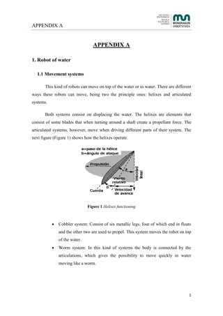
- 1. APPENDIX A 1 APPENDIX A 1. Robot of water 1.1 Movement systems This kind of robots can move on top of the water or in water. There are different ways these robots can move, being two the principle ones: helixes and articulated systems. Both systems consist on displacing the water. The helixes are elements that consist of some blades that when turning around a shaft create a propellant force. The articulated systems, however, move when driving different parts of their system. The next figure (Figure 1) shows how the helixes operate. Figure 1 Helixes functioning Cobbler system: Consist of six metallic legs, four of which end in floats and the other two are used to propel. This system moves the robot on top of the water. Worm system: In this kind of systems the body is connected by the articulations, which gives the possibility to move quickly in water moving like a worm.
- 2. APPENDIX A 2 Jellyfish system: Consists of eight metallic arms and a silicone film tied to them. When moving the metallic arms, the silicone film displaces the water obtaining the robots movement. 1.2. Material election In this type of robots the material choice is very important, since upon this depends whether the robot will have good buoyancy or not. Nowadays used materials have been analyzed, by means of some robot examples, in order to choose the most adequate material. Three have been the robots analyzed: a stainless steel robot that can submerge 50 meters in water, a titanium robot prepared to work in salty water and a plastic robot that works in bland water. In the next figure (Figure 2) appears a water rescue robot. Figure 2 Water rescue robot 1.3. Sensors, cameras and other kind of complements All these type of systems are used in different situations even if they principle application are surveillance, rescue and underwater repair labours. In order to carry out these assignments in a correct way, these robots must consist of some special implements. The next ones are the most important ones:
- 3. APPENDIX A 3 First aid kit compartment: Necessary in a rescue labor to help hurt person. Camera / Flashlight: In order to see what is happening in the water when water surveillance. Mechanical arm: Very useful to pick any object or mark in the water. If a modulus to weld is added, the robot will be able to repair leaks in any pipe. 2. Air robots In order to achieve a robot fly it must have a very low density, that is to say, it can have a heavy weight. Apart from that, the helixes must have a minimum power in order to maintain the robot in air and not suffer too many vibrations. Figure 3 Dron To extinguish a fire, to help in rescue labors and to access certain regions where human can’t go are used drons, air robots (Figure 3). Most of the drons are equipped with a camera to see what it is happening and also to drive them. Apart from that, they are made with low density materials, such as, polypropylene foam, carbon fiber, fiberglass… Drons used in rescue labors are rigged with a camera used to see what is happening and thermal camera in order to be able to see silhouettes. They have also a
- 4. APPENDIX A 4 microphone in order to communicate the person who is going to be rescued, in a hypothetical case, with the center which is controlling the robot. These kind of drons are able to fly till high altitudes and if the rescue labor is going to last a long time, there are some robot equipped with photovoltaic panels which charge the robot in order to make this endure 24 hour underway. They can also incorporate a GPS if it is wanted to be controlled from the center and not from the ground. Most of the drons fly thanks to helixes which are start up by an electric motor and put in motion by some gears (Figure 4). Figure 4 Relation between the helix and the motor 3. Earth robot All the robots that move from earth must have some characteristics that make the robot function in the adequate way. The movement of the robot must allow the robot move from any kind of surfaces, in order not to have any movement limit. The robot must be as quick as possible, having a simple movement system. Precision of the in all the movement and operations must be achieved. Robots usually have some sensors and systems, such as GPS and camera, attached obtain the best results.
- 5. APPENDIX A 5 In order to achieve the previous characteristics, is necessary to make a research about the next points: Different systems used to walk through earth. Light and resistant materials. Type of sensors and its applications. 3.1. Movement systems Big earth robots use wheel or quad-track system to move through earth. In the case of smaller robots, another type of movement systems are starting to appear. a) 4x4 wheel system By means of this system, the motor of the robot transmits the tensile force to the four wheels, firstly being transmitted to the differential. The main aim of the differential is to control the different rotation of each shaft or wheel. These are the advantages of this system: The perfect control of the vehicle. The achievement of a good adherence of the robot and the surface. Depending on the adherence, a perfect distribution of the torque. Still, there are also some disadvantages in what this system is concerned: It has a high consumption as the transmission system is all the time connected. The robot’s weight increases a lot. It is quite expensive. b) Crawler track system This system enables the robot move in an adequate way in irregular surfaces. The system consists of a group of modular chain system. This system is used by a lot of types of vehicles, such as, heavy trucks, tanks… All the chains that complete the
- 6. APPENDIX A 6 modular chain system must be firmly tied between them, maintaining every time the flexibility necessary (Figure 5). Figure 5 Crawler track system's wheel The modular chain system allows distributing the weight in a bigger area compared with the wheels system, letting the vehicle work in more type of surfaces. The operation of the crawler track system can be simply explained with the next image (Figure 6). Figure 6 Parts of the crawler track system
- 7. APPENDIX A 7 The first wheel is the wheel of the back transmission system and the fourth of the transmission system of the front. The element with the number two is the modular chain that completes the system. The sixth wheel, however, is the tensor roller. In the case of the fifth wheels, these are the ones that are in contact with the surface. c) “C” appearance legs robot These kinds of robots only work from the sand, and even if they aren’t very common, they obtain very good results. This system consists of six “C” appearance legs robot, which are programmed to turn in threes, entering in the sand and in this way moving the robot (Figure 7). Figure 7 "C" appearance legs robot
- 9. APPENDIX C 1 APPENDIX C In the next pages extra information of the structural analysis has been exposed. The next three pictures (Figure 1, 2 and 3) show fully the aspect will have the structure when the overweight is placed in the sheet. The overweight is going to be situated in the sheet and the electrical elements are going to be collocated in the extreme of the structure will produce those deformations. a) General view Figure 1 General view of the structure´s displacement b) Aside view Figure 2 Aside view of the structure´s displacement
- 10. APPENDIX C 2 c) Frontal view Figure 3 Frontal view of the structure´s displacement In addition, the maximum deformation will be in the sheet as it can be seen in the following figure 3. Therefore, once the sheet is deformed the tubes that are holding it will deform too. Figure 4 shows the displacement of the elements and in this case, the areas in green means that those parts of the elements will displace minimally 0.25 mm. Figure 4 Structure´s displacement up to 0.25 millimeters On the other hand, the plate of the motor will have an unitary deformation of 4 10229.3 , as it can be seen in figure 5.
- 11. APPENDIX C 3 Figure 5 Maximum unitary deformation of the motor´s plate The three-wheel star has been analyzed in the next pages. Figure 6 shows a comparison between the two different forces that the different three-wheel tubes suffer, such as 271 N and 89 N. It can be appreciated that the position of the maximum tension is in the tube clamping, but the value of this tension logically is different. Figure 6 Comparison of stress concentrations Besides, figure 7 shows the unitary deformation of the tree-wheel stars depending on their forces. It can be seen that when more force the tubes have, higher is the unitary deformation.
- 12. APPENDIX C 4 Figure 7 Comparison of unitary deformation The unitary deformation of the tube is smaller than the structure, so the strain gage will be collocated in the structure in order to measure the real deformation. If the designer must put another gage, it will be collocated in the tube. Finally, a comparison has been realized with the same parameters (Figure 8). But in this case, it has been realized to see the differences of the displacements. Figure 8 Comparison of displacements
- 13. APPENDIX D 1 APPENDIX D Positioning of the gages Before explaining the process, it would be interesting to remember that the gage used in this case is composed of three gages to be able to measure the deformation in different directions and that each gage has two output wires. 1. Preparation For bonding and lead wire connection, the following items are required: Strain gages Bonding adhesive Connecting terminals Test specimen Solvent Cleaning tissue for industrial use Soldering iron Solder Abrasive paper (120-320 grit) Rule Tweezers Extension lead wire Polyethylene sheet Nippers
- 14. APPENDIX D 2 2. Surface preparation Before bonding, is necessary to remove all the grease, rust, paint… from the bonding area. Sand an area somewhat larger than the bonding area uniformly and finely with the abrasive paper. Taking into account that the surface in which the strain gage will be stuck is aluminium, finish the surface with #240 to #320 abrasive papers. 3. Fine cleaning Clean the bonding area with industrial tissue paper or cloth soaked in a small quantity of chemical solvent such as acetone. Continue cleaning until a new tissue or cloth comes away completely free of contamination. Following the surface preparation, be sure to attach the gage before the surface becomes covered with an oxidizing membrane or becomes newly contaminated. 4. Apply bonding adhesive Drop the proper amount of adhesive onto the back of the gage base (Figure 1). Usually one drop or adhesive will suffice, but you may increase the number of drops according to the size of the gage. Use the adhesive nozzle to spread the adhesive over the back surface thinly and uniformly. Figure 1 Use of the adhesive tape for the positioning o the gage
- 15. APPENDIX D 3 5. Curing and pressing Place the gage on the guide mark, place the polyethylene sheet onto it and press down on the gage constantly using the thumb or a gage pressing device (Figure 2). This should be quickly as the curing process is completed very fast. The curing time varies depending on the gage, test specimen, temperature, humidity and pressing force. The curing time under normal conditions is 20-60 seconds. Figure 2 Stuck of the gage using the adhesive tape 6. Raising the gage leads After curing completely, remove the polyethylene sheet, and raise the gage leads with a pair of tweezers. 7. Bonding connecting terminals Position the proper size connecting terminals adjacent to the bonded gage. A distance of 3-5 mm generally allows for easier wiring later.
- 16. APPENDIX D 4 8. Soldering the gage leads Wrap the gage leads around the connection terminal wires. Solder the junction area with a little slack in the gage leads, taking care to prevent excessive tension during measurement. 9. Soldering extension lead wires Solder an extension lead wire to the terminal wires on the opposite side of the connecting terminals. Clip off any excess extension lead wire with a pair of pliers or wire cutters. Figure 3 Collocation of the gages with its wires in the robot
- 17. APPENDIX D 5 Calculation of the deformation using a gage Verification of the gage The first step after the positioning of the gages is to check that they work properly. To do that, a gage installation tester will be used (Figure 4). With this machine, the state of the resistance of the gage will be analyzed. Figure 4 Gage installation tester Easy instructions for the connection of the wires can be found on the cover of the installation tester. Once the wires have been connected, and before test the gage, its properties must be taken into account. In this case, the properties of the used gages can be seen in figure 5:
- 18. APPENDIX D 6 Figure 5 Properties of the used gages The most important properties are the gage resistance and the gage factor. The gage resistance is used to verify that the resistance given by the gage and to compare it with the theoretical one given by the supplier. To measure it, the green button must be pushed (Figure 6). To measure the error of the obtained value, the white button must be pushed (Figure 6). Finally, to measure the electrical insulation of the gages the orange button must be pushed (Figure 6). If all the values are correct, it means that the gage works correctly. Figure 6 Buttons of the tester needed to check the gages
- 19. APPENDIX D 7 The obtained values can be seen in table 1. Table 1 Obtained results in the testing of the gages Resistance of the gage (Ω) Gage factor Electrical insulation (GΩ) Red gage 120+0.2% 2.1 7White gage 120+0.32% Green gage 120+0.3% After check that the gages work correctly, it is time to measure the deformation of the part in which the gage has been stuck. To do this operation, Digital Strain Indicator and Switch and Balance Unit (Figure 7) have been used. Figure 7 Digital Strain Indicator and Switch and Balance Unit The only thing that has to be made is to follow the instructions of the machine. These instructions can be found in the cover of the unit (Figure 8). In this case, a quarter bridge system has been used.
- 20. APPENDIX D 8 Figure 8 Instructions of the digital Strain Indicator and Switch and Balance Unit Looking to the figure 8, the only thing that must be done is to connect one of the output wires of the gage to the red plug and the other one to the white one, as it can be seen in figure 9. Figure 9 Connection of each gage in its channel For each gage, a different channel has been used. It can be seen that one of the outputs of the green gage has been connected to the red plug of the eighth channel and the other one to the white plug. This process has been made with each gage.
- 21. APPENDIX D 9 Once that the wires have been connected, the gages must be calibrated. To do that, the balance wheel must be used. There is one for each channel, and the value of the resistance must be changed to zero. This value will appear on the screen of the machine (Figure 10). Figure 10 The screen of the machine showing a value After doing it, the gage can be used. The weight has been put and the obtained micro-unitary deformations are the following ones: Gage with red wires (ε1): 0.052 Gage with white wires(ε2): -0.173 Gage with green wires(ε3): -0.072 The obtained values will be used to achieve the results that produces the overweight. First of all, the principal strains must be calculated in order to calculate the correspondent stresses after. Maximum principal strain: 5 max 26626666 2 32 2 3121max 10258625025,5 107210173107210522101731052 2 1 2 2 1
- 22. APPENDIX D 10 Minimum principal strain: 4 min 26626666 42 32 2 3121min 10735862503.1 107210173107210522101731052 2 1 10736,12 2 1 Once the principal strains are known, it must be calculated the position of each one. Those strains will be displaced from the first axis, red gage and as ε1 is bigger than ε2, the angle to the maximum strain is rotated ϕP clockwise from the first axis, and the minimum principal strain is located at ϕP+90º, figure 11. Figure 11 Position of the principal strains º198314262.2 101731052 10173105210722 tan 2 1 2 tan 2 1 66 666 1 21 2131 P Apart from the principal strains, there is another important strain that it must be calculated, the maximum shearing strain.
- 23. APPENDIX D 11 4266266 2 32 2 31max 10261725005.2107210173107210522 2 On the other hand, when the principal strains are known, the stresses of each strain must be calculated in order to know the value of the maximum and minimum principal stresses that will affect to the tube. After that, the maximum shearing stress is going to be calculated too. Before starting analyzing the stresses, Young´s modulus and Poisson´s coefficient must be known. Taking into account that the tubes material is aluminum, those are the properties of this material. 33.0 MPa69000E MPa363716364.010735862503.133.010258625025.5 33.01 69000 1 E 45 2 minmax2max MPa09747767.1210258625025.533.010735862503.1 33.01 69000 1 E 54 2 maxmin2min MPa866880652.510261725005.2 33.012 69000 12 E 4 maxmax
- 24. APPENDIX E 1 APPENDIX E 1. LDR A LDR is an electric component whose resistance varies depending on the light received. The more light it receives, lower is the value of its resistance. A photoresistor (Figure 1) is made of a high resistance semiconductor. If incident light on a photoresistor exceeds a certain frequency, photons, particles which transmit light, absorbed by the semiconductor give electrons energy and the resulting free electrons conduct electricity lowering the resistance. Figure 1 LDR sensor The aim of using this component is to switch on the lights when it starts to get dark. Explained in another way, to get the lights switched on when the robot is in a dark place. In order to obtain this, the control of the lights of the machine is carried out with this analogue sensor, making possible to switch on and off the lights automatically. The first step to program the detector is to measure the value of the resistance of the LDR. With this measurement, is possible to known which will be the resistance values of the second resistance with the maximum and minimum voltages. These measurements have been carried out with a voltmeter, obtaining the resistance of the photo resistor when the lights intensity is maximum and minimum, both inside and outside the building. The next ones are the values obtained (Table 1):
- 25. APPENDIX E 2 Table 1 Measured values 100% light (2 kΩ) 0% light (200 kΩ) Outside 197 8.4 Inside 950 1.8 The reason for doing the measurements in different scales is that when the light intensity is too low, the value of the resistance increases till one point where the voltmeter only is able to read in a bigger scale. If the light intensity, however, is high enough, the value of the resistance decreases until a point where, with a big scale, is impossible to read. To make the calculus of the second resistance value is necessary to understand the electrical circuit. If the voltage measured is the maximum, the resistance of the LDR needs, compulsorily, to be the minimum and in the other way round. Taking into account the functioning of the circuit, the calculus have been carried out when the robot is outside, that is to say, when the intensity of the light is 100%. In this situation, the LDR resistance is much lower than when the light intensity is 0%. Taking this into account, the value of the second resistance has been calculated. RIV LDTRR R VV 2 2 inout Knowing that: Vout: voltage of the other resistance = 10 V Vin: voltage of the circuit = 24 V RLDT: Resistance measured at 10 V, the one with 100% light, 197 Ω ≈ 200 Ω R2 ≈150 Ω
- 26. APPENDIX E 3 Once the value of the resistance has been calculated, the range of the other resistances voltages has been calculated, in order to ensure that the voltage range is between 0-10 V. V28.10 200150 150 24 2 2 inout LDTRR R VV V42.00 8400150 150 24 2 2 inout LDTRR R VV As it can be seen, the range is, more or less, between the admissible values. So, the second resistance’s value will be of 150 Ω. The language that the PLC understands is the hexadecimal language. The hexadecimal system is the most popular number system used by PLCs because it allows using fewer digits than the binary or octal systems. That’s why, it’s necessary to convert the voltage analog signal in a hexadecimal binary signal. As the voltage range is between 0 to 10 V, in this case, the voltage input of the A/D conversion data is from 0000 to 0FA0 in hexadecimal system (Figure 3). Figure 2 Voltage – hexadecimal system graph The next step the PLC follows is to obtain the value of the other resistance. In this way, the system will be, every time, scaling the voltage value obtained in order to get the converted data in hexadecimal system. This is possible thanks to the linearity of the system.
- 27. APPENDIX E 4 After obtaining the converted data of the voltage measured, it is transferred to a diagram from which is obtained the intensity depending on the data sent (Figure 4). Depending on which is the intensity obtained, the PLC will give the order to switch on the lights or not. Figure 3 Hexadecimal system- Intensity graph 2. Programming To program the PLC is necessary to make the addressing of all the elements that the PLC is going to control. The addressing consists on assigning to each element a bit of the memory. As in this case the PLC used is an OMRON PLC, the input bit memory starts from 000 and the output 100. If the brand was another one, the inputs and outputs will be kept in other bits. Before the addressing in necessary to divide all the elements in analogue or digital inputs or outputs. The input elements are the elements that give to the PLC an information and the outputs are the elements that receive a command from the PLC. On the next table (Table 2) are define each element and their address:
- 28. APPENDIX E 5 Table 2 PLC addressing Digital inputs Digital outputs Element Address Element Address Start button 000.00 Relay 1 100.01 Forward 000.01 Relay 2 100.02 Backward 000.02 Relay 3 100.03 Left 000.03 Relay 4 100.04 Right 000.04 Relay 5 100.05 Inclinometer 000.05 Buzzer 100.06 Velocities switch 000.06 Lights 100.07 Automatic/manual switch 000.07 Before starting to make the program is useful to make a diagram with the steps that the PLC needs to follow to carry out all the commands that the robot needs to do, that is to say, a GRAFCET. These diagrams are very useful when starting to make a program because they pick up and schematize all the steps the program must follow. As the PLC is not able to understand and execute the GRAFCET, even if they have the same steps, the program must be done in order to make the PLC control all the commands. The following diagrams are the ones used to do the program (Figures 4, 5, 6 and 7).
- 29. APPENDIX E 6 Figure 4 Light control GRAFCET Figure 5 Inclinometer GRAFCET
- 30. APPENDIX E 7 Figure 6 Manual mode GRAFCET Figure 7 Automatic mode GRACET
- 31. APPENDIX F 1 APPENDIX F In this appendix, the calculus made to obtain the mechanizing time of each part have been explained. To calculate the price of each machine in each operation, the next table has been followed (Table 1). In this table, the taxes of each machine (€ per hour) are appeared. Table 1 Taxes per hour of different machines 1. Long square tube The raw material has been obtained from Amazon [1]. The price of this material is 10.14 € per each 1000 mm. In this case, for each part, 500mm are needed, and two parts will be needed, so the material will cost 5.07 € per part. On the other hand, is necessary to calculate the price of each machine used. To manufacture this part, the machines used have been the mechanical raw and the drill. The price of each machine is: Mechanical saw: It has been supposed that the necessary time to cut each part will be one minute and a half, in other words, 90 seconds. Drill: It has been supposed that to do all the holes of the part a minute will be needed. Taking into account the values of the taxes of the machines (Table 1), the total cost of using the both machines will be 0.92 €.
- 32. APPENDIX F 2 2. Short square tube The raw material has been obtained from Amazon [1]. The price of this material is 10.14 € per each 1000 mm. In this case, for each part, 250 mm are needed, and two parts will be needed, so the material will cost 2.53 € per part. This part is similar to the previous part, so the necessary machines will be the same. In this case: Mechanical saw: In this case, 90 seconds will be needed too for each part. Drill: It has been supposed that to do all the holes of the part ten seconds will be needed. Taking into account the values of the taxes of the machines (Table 1), the total cost of using the both machines will be 0.57 €. 3. Auxiliary shaft In this case, is necessary a tube of steel with a diameter of 12 mm. The material has been bought at INCAFE 2000 [2]. This material costs 1.05 € per meter. The initial length of the shafts (before mechanize them) is 7 mm. Twelve parts are needed, so the total length will be 936 mm. Their cost will be 0,98 €. To manufacture this part, the mechanical saw, the CNC lathe and the drill are needed. It has been supposed that the needed time for each part will be one minute, so taking into account that the tax of the mechanical saw is 20 €/h, the cost for each part will be 0.34 €. In the mechanical lathe, different operations are necessary.
- 33. APPENDIX F 3 o First, both faces of the part must be cleaned. To calculate the time, formula 1 has been used. The needed time is 0.4 second for the both faces. minA L V L T (1) o Then, the part has to be measured, and shorten it till 73.5mm. Using the formula applied before (formula 1), 1.35 second are needed to rough down it and 5.75 seconds to finish it. o The last operation in the lathe is to reduce the diameter to 10 millimeters along 13.5 millimeters. Applying formula 1 used before, it has been obtained that the necessary time is 1.6s for the rough down and 7 second to finish it. Taking all the times and the tax of the CNC lathe, the cost of using this machine will be 0.29 €. In the drill, 44 seconds will be necessary to do all the holes. As the tax of the drill is 18 €/h, the cost of this operation in this machine will be 0.22€. 4. Main shaft In this case, is necessary a tube of steel with a diameter of 12 mm. The material has been bought at INCAFE 2000 [2]. This material costs 1.05 € per meter. The initial length of the shafts (before mechanize them) is 78 mm. Twelve parts are needed, so the total length will be 936mm. Their cost will be 0.98 €. To manufacture this part, the mechanical saw, the CNC lathe and the drill are needed.
- 34. APPENDIX F 4 It has been supposed that the needed time for each part will be one minute, so taking into account that the tax of the mechanical saw is 20 €/h, the cost for each part will be 0.34 €. In the mechanical lathe, different operations are necessary. o First, both faces of the part must be cleaned. To calculate the time, formula 1 has been used. The needed time is 0,4 second for the both faces. o Then, the part has to be measured, and shorten it till 73.5mm. Using the formula applied before (formula 1), 1.35 second are needed to rough down it and 5.75 seconds to finish it. o The last operation in the lathe is to reduce the diameter to 10 millimeters along 13.5 millimeters. Applying formula 1 used before, it has been obtained that the necessary time is 1.6s for the rough down and 7 second to finish it. Taking all the times and the tax of the CNC lathe, the cost of using this machine will be 0.29€. In the drill, 44 seconds will be necessary to do all the holes. As the tax of the drill is 18 €/h, the cost of this operation in this machine will be 0.22€. 5. Framing square To manufacture this part, the necessary material has been bought at MercadoLibre [3]. The price of the square is 99 € per each three meters of material. In this case, 100 millimeters are needed, so the price of the raw material will be 3.3 €. On the other hand, the needed machines are the mechanical saw and the drill. It has been determined that to cut each part, two minutes will be needed. Knowing that four parts are needed, the total time will be eight minutes. Looking to table 1, the final price will be 2.67 €.
- 35. APPENDIX F 5 To do the holes, ten seconds will be needed for each part. Knowing that four parts are needed, and that the tax of the drill is 18€ per hour, the price of each part will be 0.05 €. So, summing all the prices, the final cost of the four parts obtained will be 6.18€. 6. Three wheel shaft These parts have been manufactured out of the university because of their difficulty. The price of each one has been 39 €, so the final price will be 156 €. 7. Three wheel tube In this case, the raw material has been bought at AKI [4]. The price of this product is 5.19 € per meter, so knowing that the total length needed is 480 mm, the price of the material will be 2.49 €. To get this part, the unique machine necessary is the mechanical saw. It is known that its tax is 20 €/h, and it has been determined that the time necessary to cut each part is 1 minute. So, the tax of the saw for each part will be 0.33 €. 8. Chock The material needed is the same than the used in the parts 1 and 2 [1]. Knowing how much does a meter cost, the price of the needed material will be 0.81 €. On the other hand, is necessary to calculate the price of each machine used. To manufacture this part, the machines used have been the mechanical raw and the drill. The price of each machine is:
- 36. APPENDIX F 6 Mechanical saw: It has been supposed that the necessary time to cut each part will be one minute and a half, in other words, 90 seconds. Drill: It has been supposed that to do all the holes of the part ten seconds will be needed. Taking into account the values of the taxes of the machines (Table 1), the total cost of using the both machines will be 0.57 €. 9. Connection block The material necessary to manufacture this part has been bought at eBay [5]. The length of each part is 30 millimeters, and knowing that the price of the block is 21.79 € per each 25 0mm, the price of each part will be 2.65 €. In the manufacture process of this part, the milling, the drill and the mechanical saw are necessary. Mechanical saw: It has been determined that to cut each part 5 minutes are necessary. There are four parts, and knowing the tax of the mechanical saw, the final price of the saw for all the parts is 6.67 €. Milling: The central hole of the part will be done in the milling. Using the formula 1, the time obtained has been 157 seconds per part. Knowing that the tax of the conventional milling is 32 € per hour, and taken into account that there are four parts, the price of the machine will be 1.53 €. Drill: To do the small holes, the drill has been used. It has been determined that the necessary time in this machine per part will be 40 seconds. The tax of the drill can be seen in table 1, so for each part, the cost of the drill will be 0.2 €.
- 37. APPENDIX F 7 10. Base sheet The necessary raw material to manufacture this part has been bought at Mastil- Boom [6]. After a negotiation with the supplier, a part with the dimensions 200x310x5 has been bought paying 6.5 €. The necessary machines are the shears and the drill. The shears has been used to reduce the length of the sheet from 200 mm to 180 mm. The time required is 1.5 seconds. Knowing that the tax of the shears is 20 € per hour, the price will be 0.008 €, so this price won´t be taken into account. In this case, 5 minutes will be needed to do all the holes in the drill. Knowing this and the tax of this machine, it has been obtained that the cost of this operation will be 1.5 €. 11. Motor plate This part has been bought at the same than the last one explained before, Mastil- Boom [6]. In this case, the selected sheet is the one that costs 3.19 €. Two are needed, so the final cost of the raw material will be 6.38 €. On the other hand, the shears and the drill are needed. The shears has been used to reduce the length of the sheet from 150mm to 115mm and the width from 100mm to 85mm. The time required is 3 seconds. Knowing that the tax of the shears is 20€ per hour, the price will be 0.01€. In this case, three minutes will be needed to do all the holes in the drill. Knowing this and the tax of this machine, it has been obtained that the cost of this operation will be 0.9 €.
- 38. APPENDIX F 8 12. Nerve The material to manufacture has been bought in Mastil-Boom too, but the dimensions are different [7]. The whole sheet costs 16.94 €, but only a part is need. Each part needed represents a 10% of the whole sheet. Three parts are needed, so the final cost of the needed part of the sheet will be 5.08 €. The machines needed to manufacture this part are the shears and the drill. The shears width of the sheet. The time required is five seconds. Knowing that the tax of the shears is 20 € per hour, the price will be 0.02€. In this case, 10 seconds will be needed to do all the holes in the drill. Knowing this and the tax of this machine, it has been obtained that the cost of this operation will be 0.05 €. The final cost of the machines will be 0.07 € per part. 13. Tensor plate In this case, the necessary material has been bought at Mastil-Boom [11]. The price of all the raw material will be 2.12 €, because four plates are needed. In this case, the needed machines will be the shears and the drill. The shears to adjust the width of the sheet. The time required is 5 seconds. Knowing that the tax of the shears is 20 € per hour, the price will be 0.02 €. In this case, three minutes will be needed to do all the holes in the drill. Knowing this and the tax of this machine, it has been obtained that the cost of this operation will be 0.9 € per part.
- 39. APPENDIX F 9 14. Tensor shaft The necessary material has been bought at INCAFE 2000 [2]. Each part is 65mm long, and there are two parts, so the needed length will be 0.13 m. Knowing this and the price of the shaft per meter, the final cost of the material needed will be 0.14 €. In this case, the only machine needed is the mechanical saw. It has been determined that the needed time will be one minute to cut each part, so the price due to use the saw will be 0.67 €. 15. Sheets shaft This type of shafts have been bought at eBay [8].The price per meter is 1.42 €. Six parts are needed, and each one is 100mm long, so the final cost of the raw material will be 0.85€. In this case, the machine used will be the mechanical saw. It has been determined that the time to cut each one will be 55 seconds, and taking into account that there are six parts, the final price of the saw will be 1.83 €. 16. Holes sheet This part is made of steel and the needed sheet has been bought at iTeC [9]. The cost of each square meter is 18.85€, and the area of the sheet is 0.054 m2 , so the needed material needed in this part costs 1.02 €. The machines needed to manufacture this part are the shears and the drill. The shears to adjust the width of the sheet. The time required is five seconds. Knowing that the tax of the shears is 20 € per hour, the price will be 0.02 €.
- 40. APPENDIX F 10 In this case, three minutes will be needed to do all the holes in the drill. Knowing this and the tax of this machine, it has been obtained that the cost of this operation will be 0.9 € per part. The final cost of the machines will be 1.1 € per part. 17. Star These parts have been manufactured out of the university because of their difficulty. The price of each one has been 13.5 €, so the final price will be 108€. 18. Wheel In this case, is necessary an aluminum shaft with a diameter of 70mm. The material has been bought at R. Andade [11]. This material costs 66.48€ per meter. The initial length of the wheels (before mechanize them) is 35 mm. Twelve parts are needed, so the total length will be 420 mm. Their cost will be 27.92 €. To manufacture this part, the mechanical saw, the CNC lathe and the drill are needed. It has been supposed that the needed time for each part will be ten minutes, so taking into account that the tax of the mechanical saw is 20€/h, the cost for each part will be 3.34 €. In the mechanical lathe, different operations are necessary. o First, both faces of the part must be cleaned. To calculate the time, formula 1 has been used. The needed time is 0.7 second for the both faces. o The next operation is to reduce the diameter to 66 millimeters along 13.5 millimeters. Applying formula 1 used before, it has been obtained that the necessary time is 15 seconds for the rough down and one minute and a half to finish it.
- 41. APPENDIX F 11 o Finally, the part has to be measured, and shorten it till 31 mm. Using the formula applied before (formula 1), 11 second are needed to rough down it and one minute to finish it. Taking into account all the times and the tax of the CNC lathe, the price of each wheel will be 3.2 €. In the drill, three minutes will be necessary to do all the holes. As the tax of the drill is 18 €/h, the cost of this operation in this machine will be 0.9€.
- 42. APPENDIX F 12 References [1]: Amazon. Bricolaje y herramientas. [Online] [3-06-2015] [http://www.amazon.es/GAH-Alberts-472856-hueco-cuadrado- aluminio/dp/B002SAIUIO ] [2]:Incafe 2000. Macizos de hierro. [Online] [3-06-2015] [http://www.incafe2000.es/lng/Esp/Producte/producte/133730/cat/macizos_redondos] [3]: MercadoLibre Electrónica, Audio y Video, Bafles, Soportes y Tripodes, Otros. [Online] [2015-06-04] [http://articulo.mercadolibre.com.ar/MLA-558902493- perfil-angulo-l-32x32-vartilla-aluminio-3-metros-anvil-rack-_JM] [4]:AKI. Ferreteria para la vivienda. [Online] [2015-06-03] [http://catalogo.aki.es/ferreteria/ferreteria-para-la-vivienda/perfil-tubo-redondo- aluminio-bruto/idp7086] [5]: eBay. Equipamiento y maquinaria, Metalurgia y Manufactura. [Online] [04- 06-2015] [http://www.ebay.es/itm/like/171694060481?limghlpsr=true&hlpv=2&ops=true&viphx =1&hlpht=true&lpid=115] [6]: Mastil-Boom. Placas de aluminio. [Online] [04-06-2015] [http://mastil- boom.com.es/presta/es/32-aluminio-100mm-x-5mm] [7]: Mastil-Boom. Placas de aluminio, Medidas especiales. [Online] [04-06- 2015] [http://mastil-boom.com.es/presta/es/medidas-especiales/507-placa-de-aluminio- 300x300x6.html] [8]: Mastil-Boom. Placas de aluminio. [Online] [04-06-2015] [http://mastil- boom.com.es/presta/es/aluminio-100mm-x-5mm/115-placa-aluminio-50x50x5.html] [9]: eBay. Equipamiento y maquinaria, Material/Utillaje Construcción. [Online] [05-06-2015] [http://www.ebay.es/itm/like/171413711652?limghlpsr=true&hlpv=2&ops=true&viphx =1&hlpht=true&lpid=115 [10]: iTec. Chapa de acero inoxidable para revestimientos. [Online] [05-06- 2015] [http://itec.cat/noumetabase2.e/consultes.aspx?paraula=B8635AA6]
- 43. APPENDIX F 13 [11]: R. Andrade. Aluminio, Barras. [Online] [05-06-2015] [http://www.randrade.com/barras/209-barra-aluminio-7075-t6-redonda.html]