Downloaded 162 times


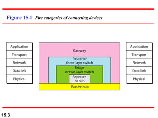
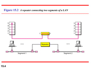


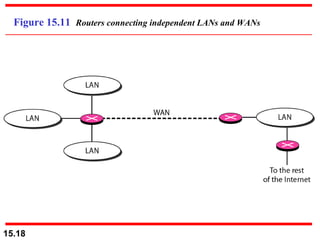
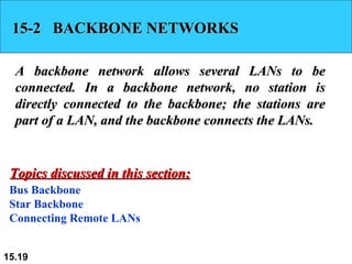
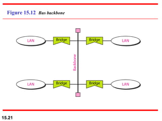


This document discusses different types of connecting devices used in computer networks, including passive hubs, active hubs, bridges, switches, routers and gateways. It also covers backbone networks that allow multiple LANs to be connected using bus or star topologies. Finally, it introduces virtual LANs (VLANs) which use software rather than physical wiring to configure local area networks and control communication between switches.