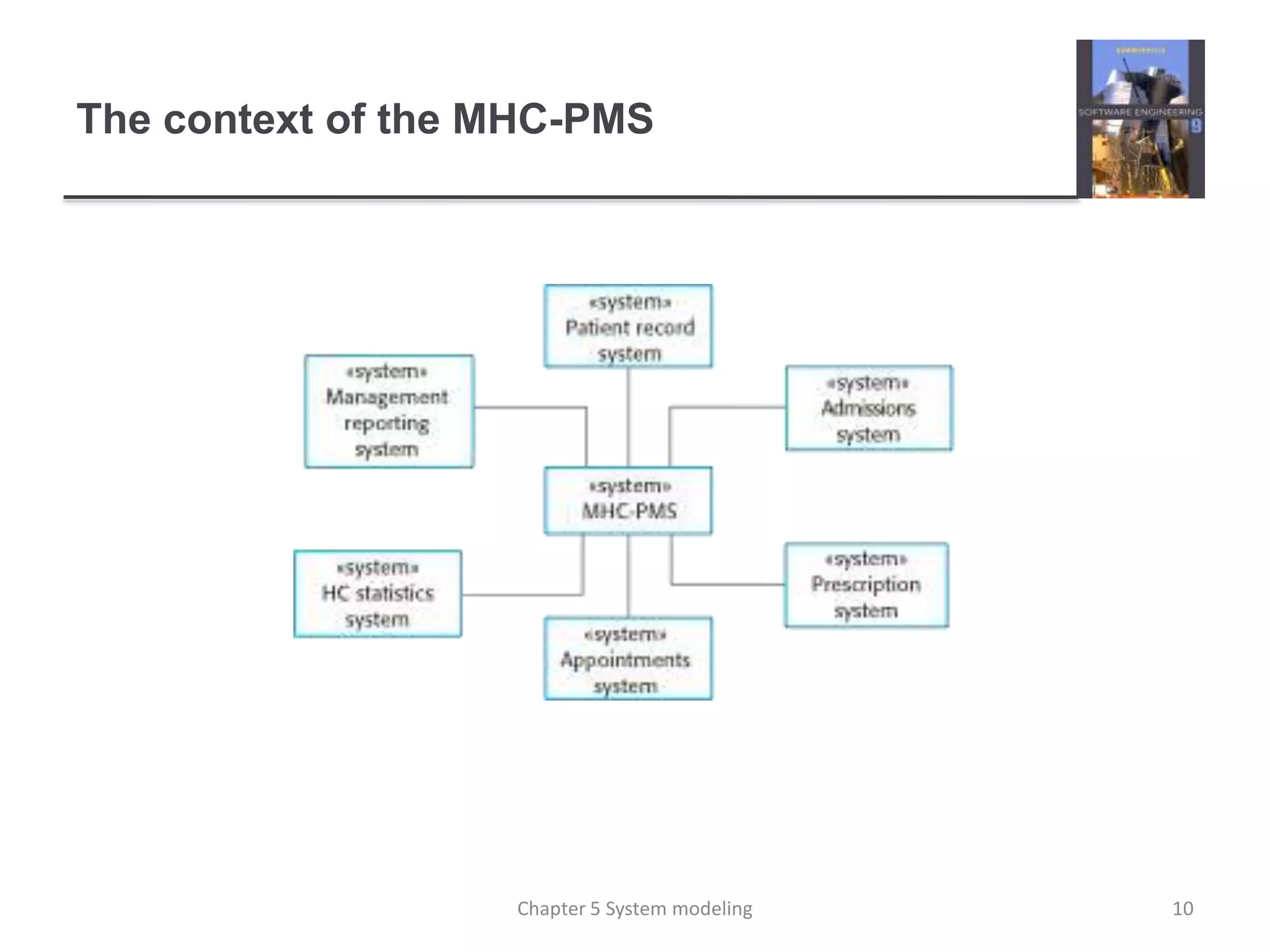
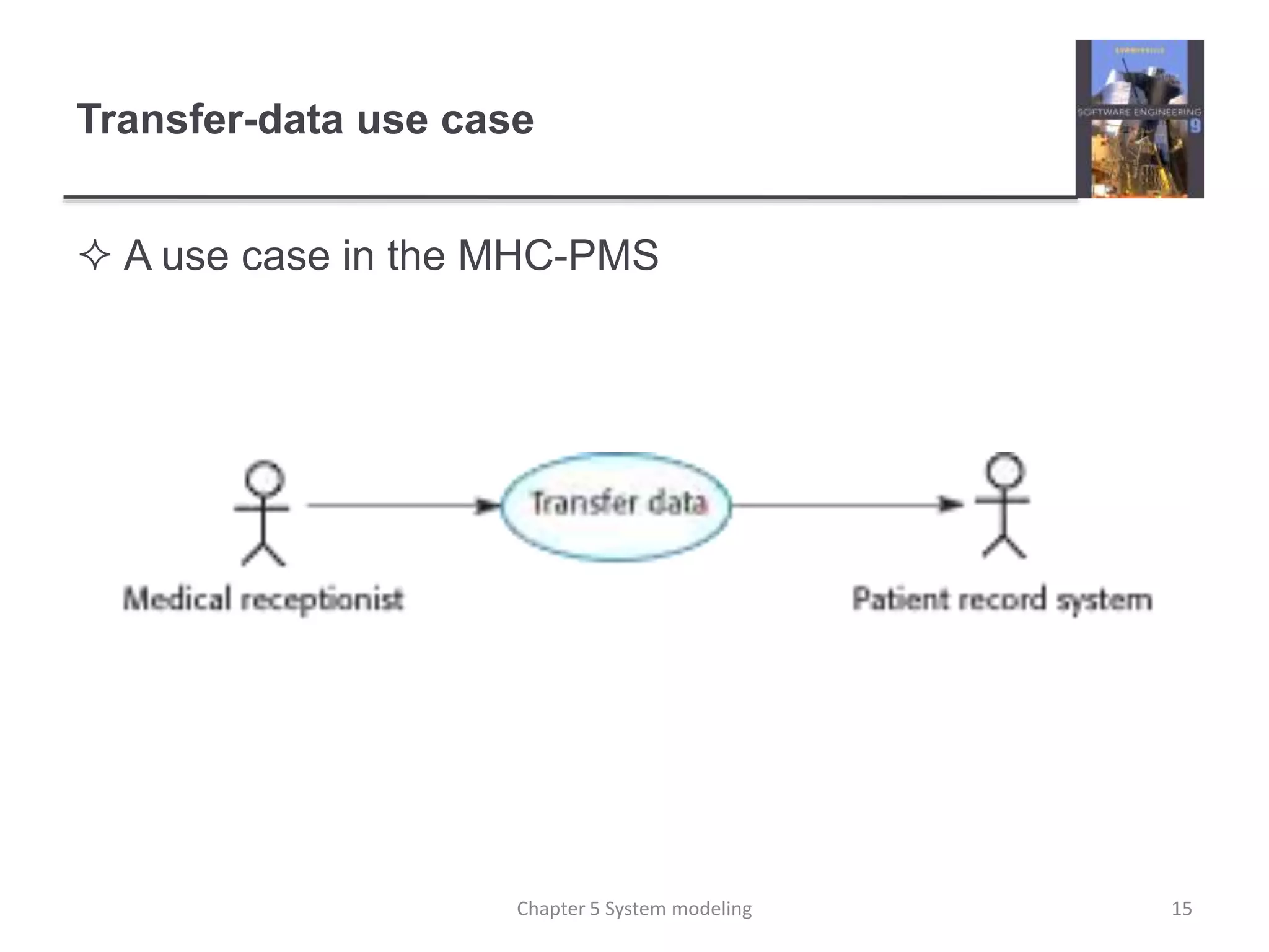
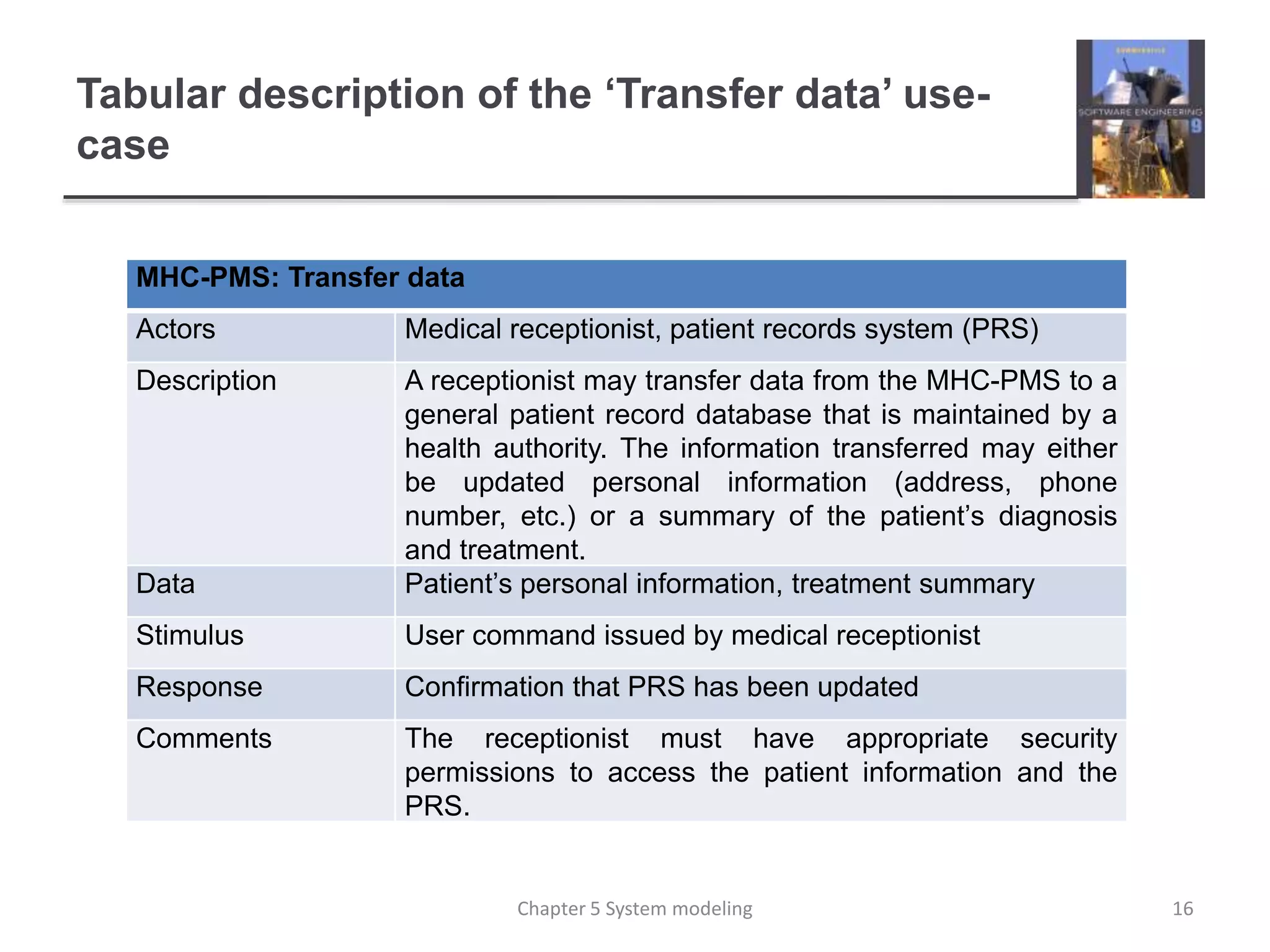
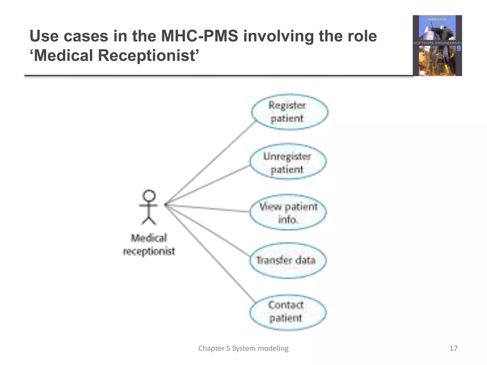
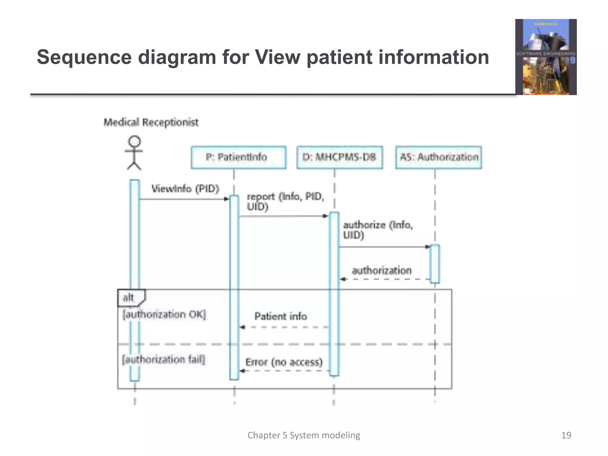
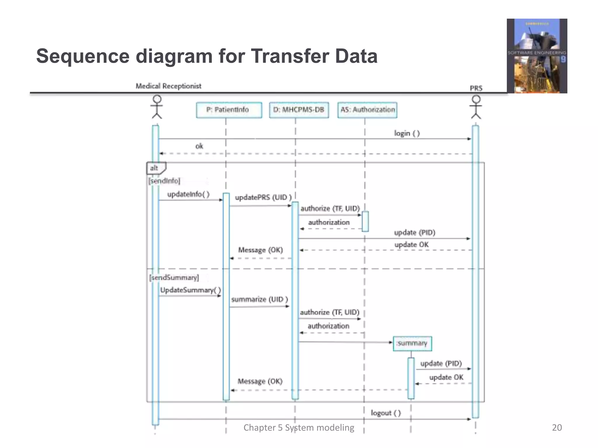
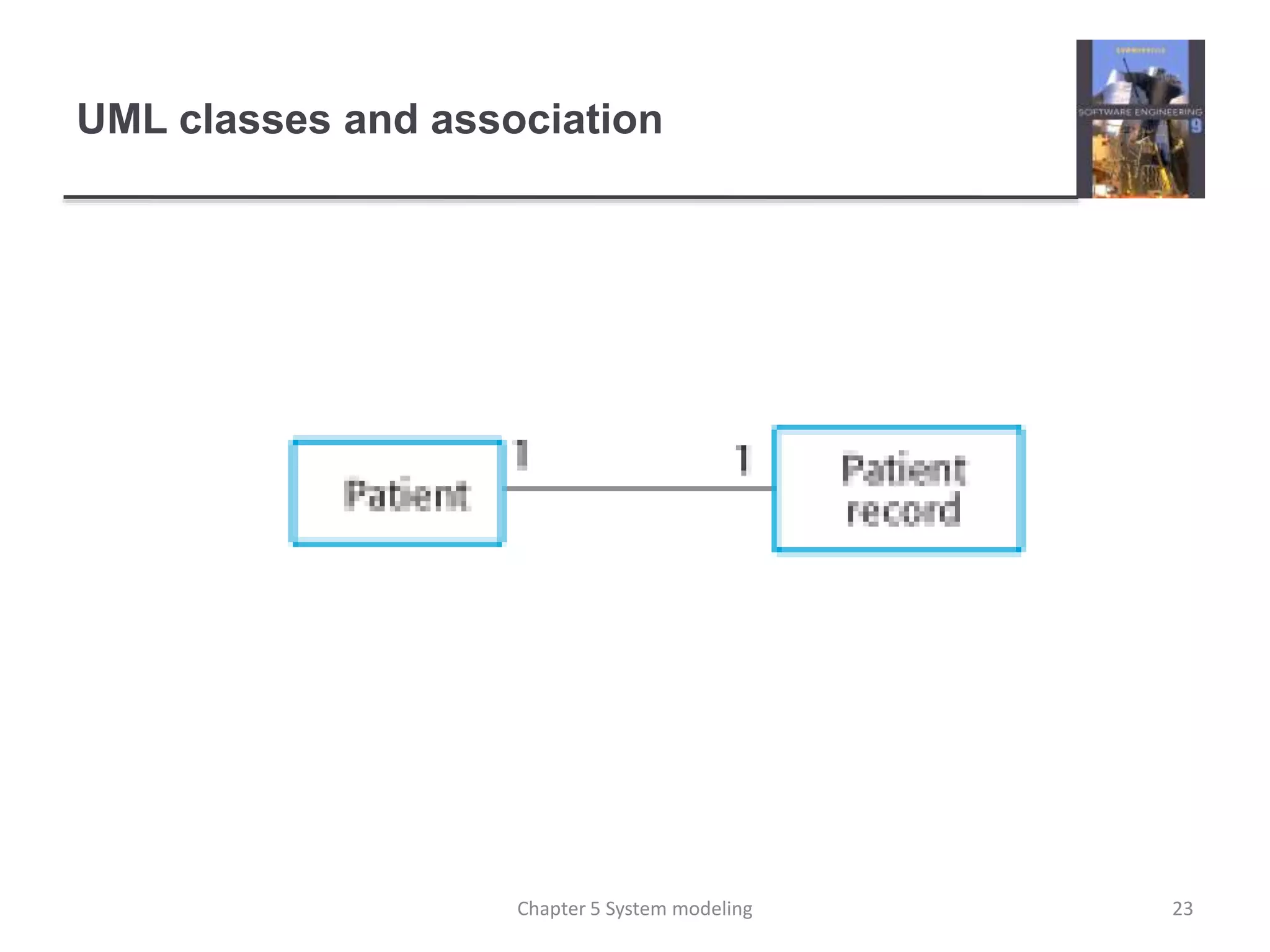
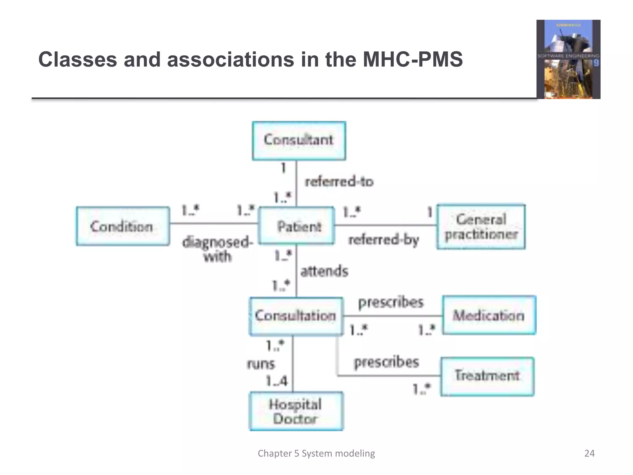
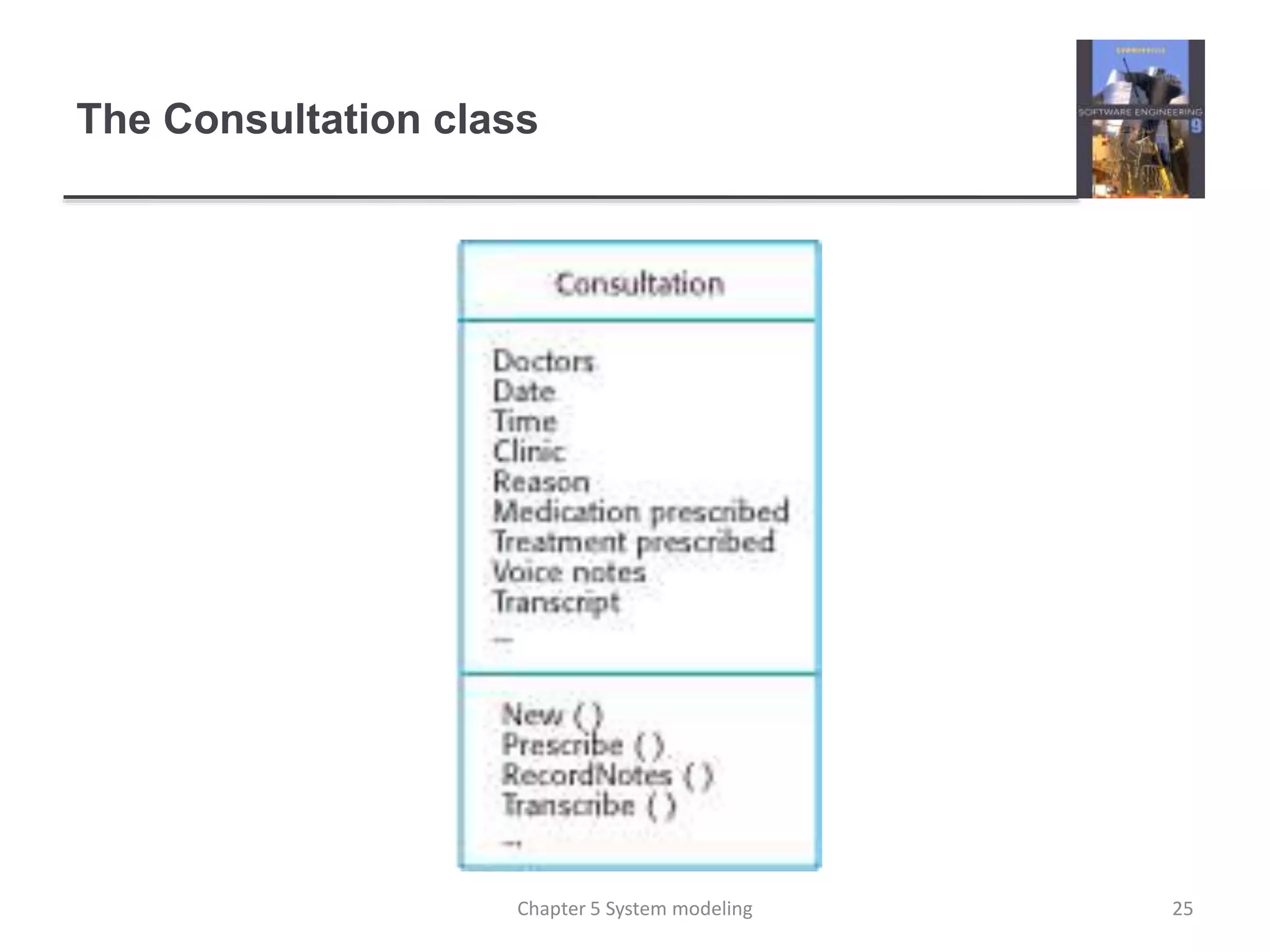
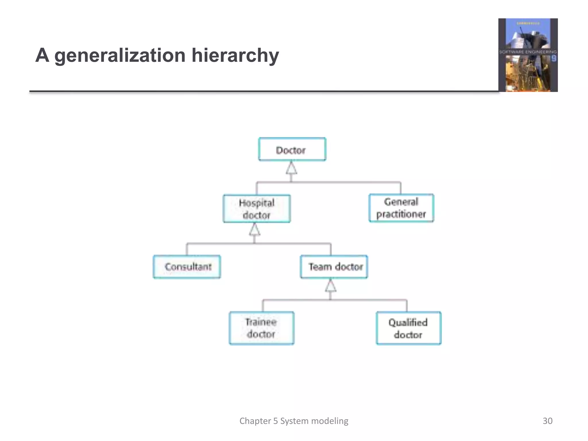
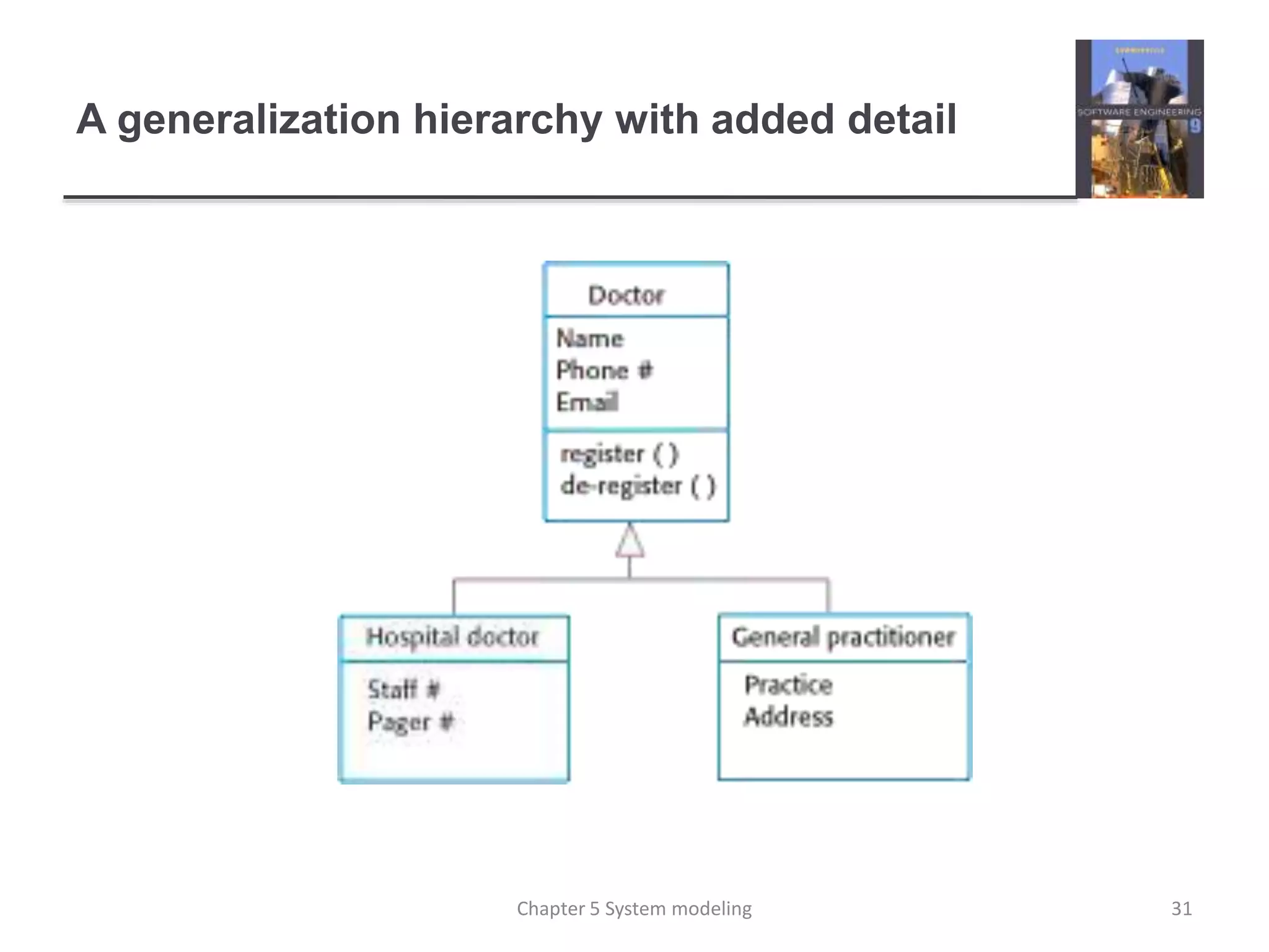
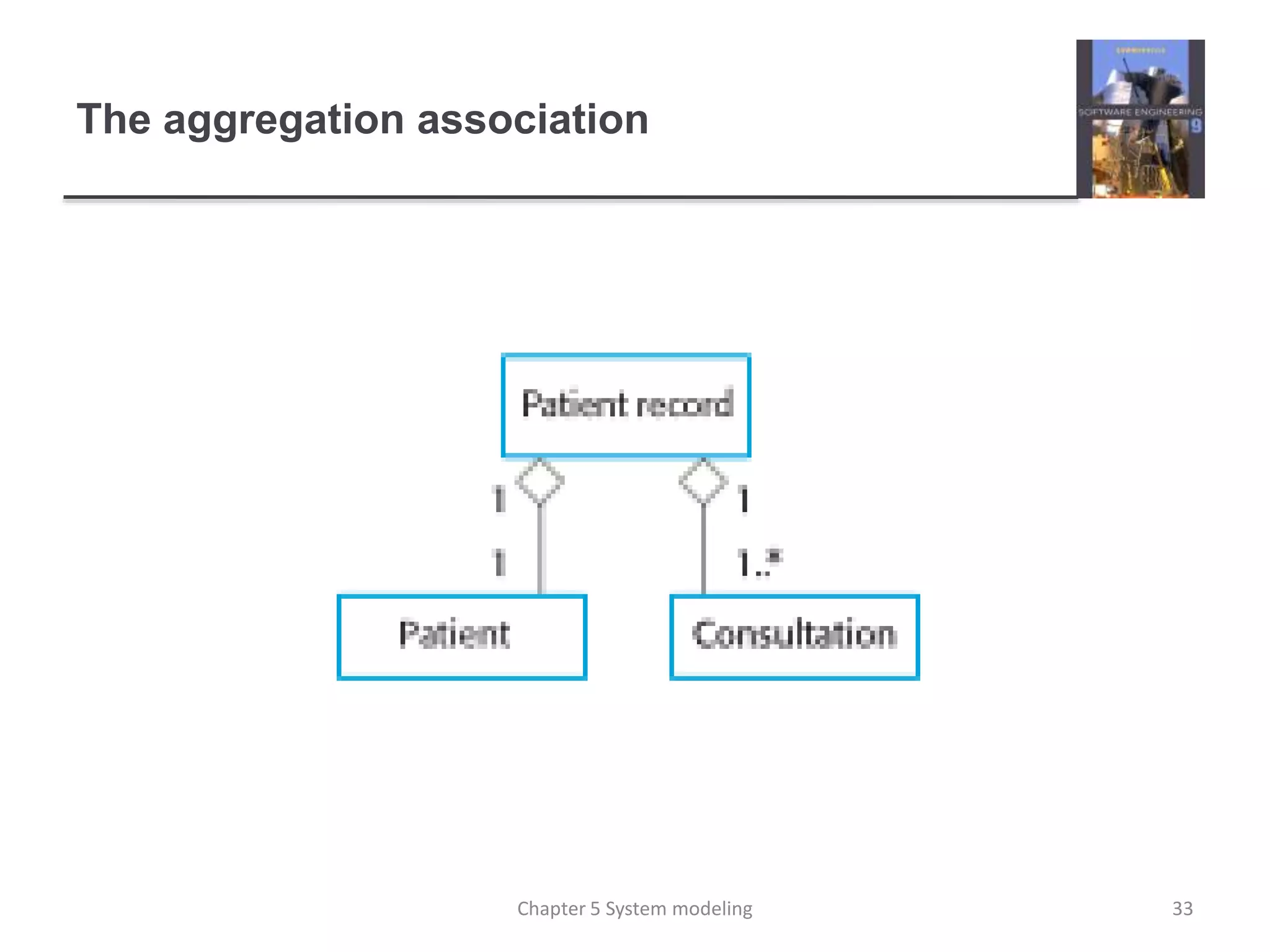
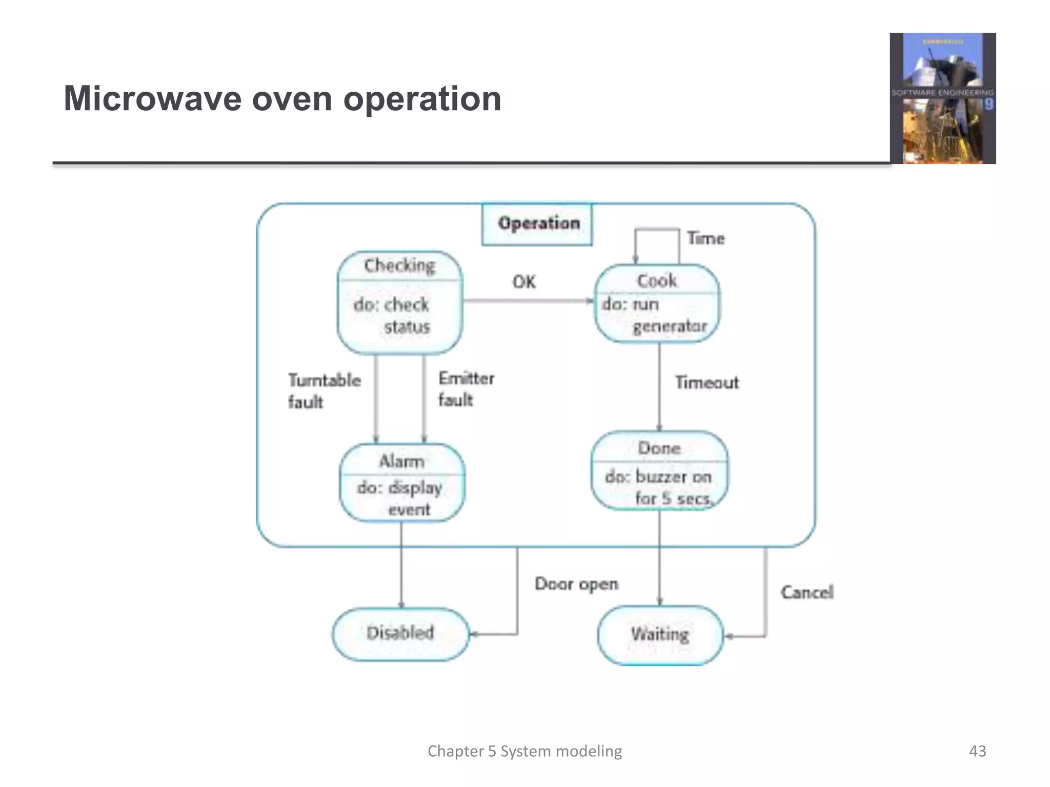
The document discusses different types of system models, including context models, interaction models, structural models, and behavioral models. It provides examples of each type of model using a case study of a mental health care patient management system (MHC-PMS). Context models show the environment and other related systems. Interaction models include use case diagrams and sequence diagrams to illustrate interactions between users and the system. Structural models, like class diagrams, depict the organization and architecture of a system through classes and their relationships.
System modeling involves developing abstract models of a system from different perspectives using graphical notations like UML. Models are used during requirements, design, and documentation of a system. There are four main types of system modeling: context modeling defines system boundaries; interaction modeling captures user and component interactions through use cases and sequence diagrams; structural modeling shows system design and architecture using class and generalization diagrams; and behavioral modeling depicts system behavior over time.
Software engineering ,system modeing >>Abu ul hassan sahadviAbuulHassan2
System modeling involves developing abstract models of a system from different perspectives to help understand its functionality. Common modeling techniques include use case diagrams, which show interactions between a system and external actors, and class diagrams, which define the system's classes and their relationships. Behavioral models depict how a system responds to stimuli over time through states and transitions. System modeling aids communication and ensures requirements and design match customer needs.
The document discusses context models and their use in system modeling. Context models illustrate the operational context of a system by showing what lies outside its boundaries, including other systems in the environment. They help define a system's boundaries and show how IT applications fit into the context of people and organizations. Two examples are provided: (1) a Mental Health Care Patient Management System (MHC-PMS) and its connections to other clinical systems; (2) an Automated Teller Machine (ATM) and its links to banking systems. Context models on their own do not show relationships between external systems, so additional models are needed.
System modeling helps analysts understand a system's functionality and communicate with customers. Models abstractly describe systems and create visual representations of proposed databases to ensure all requirements are gathered accurately. Different diagrams like entity relationship diagrams and process flow diagrams illustrate identified business processes, rules, entities, and units. Logical modeling involves gathering information to produce diagrams and reports. Physical modeling designs an actual database according to logical model requirements. Data flow modeling is a mature technique used to provide detailed models of all system processes.
SE_Lec 05_System Modelling and Context ModelAmr E. Mohamed
System modeling is the process of developing abstract models of a system using graphical notations like the Unified Modeling Language (UML) to represent different views of a system. Models help analysts understand system functionality and communicate with customers. Models of existing and new systems are used during requirements engineering to clarify current systems, discuss strengths/weaknesses, and explain proposed requirements.
System modeling involves developing abstract models of a system from different perspectives using notations like UML. Models are used during requirements, design, and documentation. Common model types include context models, interaction models using use cases and sequence diagrams, structural class diagrams, and behavioral state diagrams. Model-driven engineering aims to generate implementations automatically from models. Key aspects of software design include understanding interactions, architectural design, identifying objects, developing design models, and specifying interfaces. Design patterns provide reusable solutions to common problems.
The document discusses system modeling and different types of models used during requirements engineering including context models, data flow diagrams, state machine models, semantic data models, object models, and sequence diagrams. It also introduces the Unified Modeling Language (UML) notation and explains how analysis workbenches can support system modeling.
This document provides an introduction to system dynamics. It defines a system as a collection of interacting components with defined boundaries and inputs/outputs. Dynamic systems change over time even if inputs are constant, while static systems only depend on current inputs. Common dynamic systems include mechanical, electrical, thermal, and fluid systems. System dynamics involves defining a system, creating a mathematical model, simulating the model's behavior, and making recommendations. Models allow studying systems without experimenting on real systems. Simulation uses models to compute how systems react to inputs over time.
Use Case Modeling in Software Development: A Survey and TaxonomyEswar Publications
Identifying use cases is one of the most important steps in the software requirement analysis. This paper makes a literature review over use cases and then presents six taxonomies for them. The first taxonomy is based on the level of functionality of a system in a domain. The second taxonomy is based on primacy of functionality and the third one relies on essentialness of functionality of the system. The fourth taxonomy is concerned with supporting of functionality. The fifth taxonomy is based on the boundary of functionality and the sixth one is related to generalization/specialization relation. Then the use cases are evaluated in a case study in a control command police system. Several guidelines are recommended for developing use cases and their refinement, based on some
practical experience obtained from the evaluation.
This document discusses different types of simulation models. It describes:
1) Static vs dynamic models, with dynamic models changing over time and static models as snapshots.
2) Deterministic vs stochastic vs chaotic models, depending on how predictable the behavior is.
3) Discrete vs continuous models, with discrete changing at countable points and continuous changing continuously.
4) Aggregate vs individual models, with aggregate models taking a more distant view and individual models a closer view of decisions.
1) Mathematical modeling formulates problems or physical systems into mathematical language using equations that can then be solved using numerical methods, graphics, or analytical solutions.
2) The key components of a mathematical model are dependent variables, independent variables, parameters, and forcing functions.
3) Mathematical models can be classified as linear or nonlinear, deterministic or probabilistic, static or dynamic, and lumped or distributed parameters.
1. The document discusses simulation as a technique used to study and analyze the behavior of systems over time. Simulation involves creating a computer-based model of a real-world system to draw conclusions about how it operates.
2. Simulation can be used for task training, decision-making, scientific research, and predicting the behavior of natural systems. It allows testing alternatives without committing resources.
3. The document provides examples of how simulation can be used to model the operations of cooperative societies and banks to help students better understand commercial mathematics topics.
1. The document discusses simulation as a technique used to study and analyze the behavior of actual or theoretical systems by creating computer-based models. It is used when directly studying real systems is not possible or practical.
2. Simulation models can be static or dynamic, discrete or continuous, and deterministic or stochastic. They are composed of mathematical and logical relationships that are analyzed using numerical rather than analytical methods.
3. Simulation has many applications including manufacturing and materials handling systems. It allows testing designs and systems virtually before implementing them in the real world. It provides insights into how systems work and which variables most impact performance.
System model.Chapter One(GEOFFREY GORDON)Towfiq218
This document provides an overview of system modeling concepts. It defines what a system is and basic system components like entities, attributes, and activities. It discusses different types of systems like open vs closed systems, stochastic vs deterministic activities, and continuous vs discrete systems. It also covers various types of models like physical, mathematical, static, and dynamic models. Specific examples are provided to illustrate concepts like static and dynamic physical and mathematical models. Principles of modeling like block-building, relevance, accuracy, and aggregation are also covered.
Multilevel System Analysis - An Introduction to Systems Thinking David Alman
This document provides an introduction to Multilevel System Analysis (MSA) as a systems thinking approach. MSA uses two keys - perspective levels and cause categories - to analyze problem situations. There are three perspective levels: referential, governance, and transactional. These levels are nested within each other and can be examined separately or together. Cause categories are direct, involving observable causes, or indirect, involving less visible interacting factors. MSA examines problem situations using these two keys to identify root causes and determine the best systems thinking methodology to address the issues.
The document discusses key concepts in system dynamics from a textbook on simulation with Promodel. It defines a system as a collection of interrelated elements that work together to achieve goals. Systems have elements like entities, activities, resources and controls. Systems can be complex due to interdependencies between elements and variability in elements. To understand system performance, metrics like flow time, utilization, value added time, waiting time and flow rate are used. The document provides examples and explanations of these concepts to help understand system dynamics.
This document summarizes a research paper about developing self-adaptive multi-agent systems using a methodology-based approach. The paper addresses two key challenges with adaptive systems: 1) ensuring the system remains coherent after adaptation and 2) allowing the system to resume functioning after adaptation while accounting for prior work. It proposes using an explicit model-based development process where the system's evolution is managed at the model level and implemented on the system. Colored Petri nets are used to describe individual agent tasks. System context is handled using Petri net properties where control flow depends only on the last marking. The methodology provides a way to develop adaptive multi-agent systems that can evolve coherently while resuming prior functioning.
In this lesson, you will develop a system using Use Cases.
You will:
Justify the need for a Use Case diagram
Identify and describe the essential elements in a UML Use Case diagram
Identifying the Actors in a System.
Identifying Use Cases in a System
Create a Use Case Diagram that shows the Use Cases in your system.
Recognize and document use case dependencies using UML notation for extends,includes, and generalization
The Analytic Hierarchy Process (AHP) and Analytic Network Process (ANP) are techniques for multi-criteria decision making. AHP structures decisions as a hierarchy, while ANP structures them as a network to account for interdependencies. Both use pairwise comparisons to measure weights and rank alternatives. The four major steps of ANP are: 1) model construction, 2) pairwise comparison matrices to derive local priorities, 3) supermatrix formation to obtain global priorities, and 4) selection of the best alternative based on overall priorities. The document then provides an example case study of applying ANP to analyze strengths, weaknesses, opportunities, and threats for an insurance company in Iran.
The Analytic Network Process (ANP) is a method for decision making and forecasting that accounts for dependence and feedback. It allows for alternatives and criteria to depend on each other in a network structure rather than a hierarchy. Feedback improves the priorities and makes predictions more accurate. The ANP involves comparing elements to obtain their priorities, organizing the criteria in a control hierarchy, and deriving a weighted supermatrix to represent the influence of elements on each other with respect to different criteria. The limiting supermatrix obtained from the weighted supermatrix can then be used to read off the desired priorities and make decisions by combining benefits, costs, opportunities, and risks.
This document discusses the role of use cases in requirements and analysis modeling. It distinguishes between black box and white box views of a system in the requirements and analysis phases. Black box views include the use case model, system interaction diagrams, system context class models, statecharts for state-dependent use cases, and test models. White box views address the internal workings of a system. The document describes how each black box view relates to use cases and requirements modeling.
This document discusses discrete and continuous simulation models. It provides examples of static vs dynamic models and deterministic vs stochastic vs chaotic models. Discrete models involve state variables that change at countable time points, like a factory production process. Continuous models involve state variables that change continuously, like fluid flow in a pipe. Transporting ore with trucks is an example of a discrete system, while the ore processing plant itself is a continuous system that can be modeled discretely or continuously. The best example given is modeling an ore processing plant and mining operations, explaining how trucks follow a discrete process but ore flow can be modeled continuously or discretized.
UML (Unified Modeling Language) is a general purpose modeling language that provides a standard way to visualize the design of a system. It uses diagrams to depict both the static structure and dynamic behavior of a system. The main types of UML diagrams are structural diagrams, which show the structure of a system, and behavioral diagrams, which show the behavior of a system. Some key UML diagrams include class diagrams, which show system classes and relationships, use case diagrams which illustrate user interactions with a system, and sequence diagrams which show the interactions between system components over time. UML was adopted as a standard in 1997 and is now managed by the Object Management Group.
This document provides an overview of the Analytic Network Process (ANP), which generalizes the Analytic Hierarchy Process (AHP) to problems that involve feedback and interdependence. The ANP uses a network structure rather than hierarchical levels and derives priority scales from matrices representing the influences between different elements. It involves constructing a supermatrix for each control criterion, weighting the supermatrices, and synthesizing the results. The ANP allows for inner and outer dependence between clusters of elements and can represent complex decision problems with feedback loops.
System simulation & modeling notes[sjbit]qwerty626
The document discusses simulation modeling and provides an introduction to the topic. It defines simulation as imitating the operation of a real-world process over time. Simulation models take the form of assumptions expressed mathematically or logically about the relationships between system entities. Simulation is appropriate when a system is too complex to understand through other means or to experiment with system changes safely. The document outlines the components of a system and types of models. It also describes the basic steps involved in a simulation study from problem formulation to implementation.
The document compares techniques for handling incomplete data when using decision trees. It investigates the robustness and accuracy of seven popular techniques when applied to different proportions, patterns and mechanisms of missing data in 21 datasets. The techniques include listwise deletion, decision tree single imputation, expectation maximization single imputation, mean/mode single imputation, and multiple imputation. The results suggest important differences between the techniques, with multiple imputation and decision tree single imputation generally performing better than the others. The choice of technique depends on factors like the amount and nature of the missing data.
System modeling involves creating abstract models of a system from different perspectives, such as context, interactions, structure, and behavior. These models help analysts understand system functionality and communicate with customers. Context models show a system's external environment and relationships. Interaction models, such as use case and sequence diagrams, depict how users and systems interact. Structural models, like class diagrams, represent a system's internal organization. Behavioral models, including activity and state diagrams, illustrate a system's dynamic response to events or data. Model-driven engineering aims to generate implementation from system models.
This document discusses system modeling and provides examples from a patient management system (MHC-PMS). It describes using different types of models to represent a system from various perspectives, including context models to illustrate the system's operational environment, interaction models like use case and sequence diagrams to show user interactions, and structural and behavioral models. Specific MHC-PMS models are presented, such as a context diagram depicting related systems, use cases for medical receptionist roles, and sequence diagrams for user tasks like viewing patient information. The key points are that complementary system models abstractly represent a system from different viewpoints like context, interactions, structure, and behavior.
This document discusses system modeling and provides examples from a patient management system (MHC-PMS). It describes using different types of models to represent a system from various perspectives, including context models to illustrate the system's operational environment, interaction models like use case and sequence diagrams to show user interactions, and structural and behavioral models. Specific MHC-PMS models are presented, such as a context diagram depicting related systems, use cases for medical receptionist roles, and sequence diagrams for user flows like viewing patient information. The key points are that complementary system models abstractly represent a system from different viewpoints like context, interactions, structure, and behavior.
This document discusses system modeling and different types of models used in system modeling. It covers context models, interaction models, structural models, behavioral models, and model-driven engineering. Some key points include:
- System modeling involves developing abstract models of a system from different perspectives or views. Models are often developed using the Unified Modeling Language (UML).
- Common model types include use case diagrams, sequence diagrams, class diagrams, state diagrams, and activity diagrams.
- Structural models show the organization and structure of a system. Behavioral models show the system's dynamic behavior and responses to events.
- Model-driven engineering is an approach where models rather than code are the primary outputs and code is generated
software engineering Chapter 5 System modeling.pptxnada99848
software engineering Ch5 System modeling 10th eddition lan sommerville-software engineering Ch5 System modeling 10th eddition lan sommerville-software engineering Ch5 System modeling 10th eddition lan sommerville-software engineering Ch5 System modeling 10th eddition lan sommerville-software engineering Ch5 System modeling 10th eddition lan sommerville-software engineering Ch5 System modeling 10th eddition lan sommerville-software engineering Ch5 System modeling 10th eddition lan sommerville-software engineering Ch5 System modeling 10th eddition lan sommerville-software engineering Ch5 System modeling 10th eddition lan sommerville-software engineering Ch5 System modeling 10th eddition lan sommerville-software engineering Ch5 System modeling 10th eddition lan sommerville-software engineering Ch5 System modeling 10th eddition lan sommerville-software engineering Ch5 System modeling 10th eddition lan sommerville-software engineering Ch5 System modeling 10th eddition lan sommerville-software engineering Ch5 System modeling 10th eddition lan sommerville-software engineering Ch5 System modeling 10th eddition lan sommerville-software engineering Ch5 System modeling 10th eddition lan sommerville-software engineering Ch5 System modeling 10th eddition lan sommerville-software engineering Ch5 System modeling 10th eddition lan sommerville-software engineering Ch5 System modeling 10th eddition lan sommerville-software engineering Ch5 System modeling 10th eddition lan sommerville-software engineering Ch5 System modeling 10th eddition lan sommerville-software engineering Ch5 System modeling 10th eddition lan sommerville-software engineering Ch5 System modeling 10th eddition lan sommerville-software engineering Ch5 System modeling 10th eddition lan sommerville-software engineering Ch5 System modeling 10th eddition lan sommerville-software engineering Ch5 System modeling 10th eddition lan sommerville-software engineering Ch5 System modeling 10th eddition lan sommerville-software engineering Ch5 System modeling 10th eddition lan sommerville-software engineering Ch5 System modeling 10th eddition lan sommerville-software engineering Ch5 System modeling 10th eddition lan sommerville-software engineering Ch5 System modeling 10th eddition lan sommerville-software engineering Ch5 System modeling 10th eddition lan sommerville-software engineering Ch5 System modeling 10th eddition lan sommerville-software engineering Ch5 System modeling 10th eddition lan sommerville-software engineering Ch5 System modeling 10th eddition lan sommerville-software engineering Ch5 System modeling 10th eddition lan sommerville-software engineering Ch5 System modeling 10th eddition lan sommerville-software engineering Ch5 System modeling 10th eddition lan sommerville-software engineering Ch5 System modeling 10th eddition lan sommerville-software engineering Ch5 System modeling 10th eddition lan sommerville
System modeling is the process of developing abstract models of a system using graphical notations like UML. System models present different views or perspectives of a system, such as external context, interactions, structure, and behavior. Common UML diagram types used in system modeling include use case diagrams, sequence diagrams, class diagrams, and state diagrams. System modeling helps analysts understand system functionality and communicate with customers.
This document provides an overview of system modeling. It discusses that system modeling involves developing abstract models of a system from different perspectives, and is commonly done using the Unified Modeling Language (UML). It also describes various UML diagram types used in system modeling like use case diagrams, class diagrams, and state diagrams. Finally, it gives examples of modeling different views of a mental health case management system, including contextual models, interaction models, structural models, and behavioral models.
This document discusses system modeling and the Unified Modeling Language (UML). It provides an overview of different types of UML diagrams including class, sequence, use case, state, and activity diagrams. It also discusses modeling systems using these diagrams to represent interactions, structures, contexts and boundaries. Specific examples are provided of using a class diagram and sequence diagram to model elements of a mental healthcare system.
This document discusses system modeling and the Unified Modeling Language (UML). It provides an overview of different types of UML diagrams including class, sequence, use case, state, and activity diagrams. It also discusses modeling concepts such as system boundaries, interactions, and structural models. Specific examples are provided including a use case diagram for a patient data transfer process and a sequence diagram for viewing patient information in a mental healthcare system.
This chapter discusses system modeling and different types of models used, including:
- Context models which illustrate the operational context of a system.
- Interaction models which model interactions between a system and its environment.
- Structural models which display the organization of a system's components.
- Behavioral models which model a system's dynamic behavior in response to events or data.
- Model-driven engineering is discussed as an approach where models rather than code are the primary outputs.
System modeling involves developing abstract models of a system from different perspectives, such as context, interaction, structure, and behavior. Various modeling techniques can be used, including use case diagrams to show interactions between a system and external actors, sequence diagrams to illustrate object interactions, and class diagrams to define system classes and relationships. Structural models represent the organization of a system, while behavioral models depict system dynamics and responses to stimuli over time. Modeling helps analysts understand system functionality and communicate requirements.
This document discusses various system modeling techniques, including context models, interaction models, structural models, and behavioral models. It provides examples of each type of model using the Unified Modeling Language (UML). Context models show the system and its relationships to other external systems. Interaction models include use case diagrams and sequence diagrams. Structural models include class diagrams, which depict classes and relationships. Behavioral models show how a system responds to events. The document also discusses object-oriented design, implementation issues, and open source development.
SE18_Lec 07_System Modelling and Context ModelAmr E. Mohamed
System modeling is the process of developing abstract models of a system using graphical notation like UML. It helps analysts understand system functionality and communicate with customers. Models present different views like external context, structural organization, dynamic behavior, and interactions. Key UML diagrams include use case, class, sequence, state, and activity diagrams. System context diagrams specifically focus on external factors and the system boundaries.
The document discusses system modeling and different types of models used during requirements engineering including context models, data flow diagrams, state machine models, semantic data models, object models, and sequence diagrams. It also introduces the Unified Modeling Language (UML) notation and explains how analysis workbenches can support system modeling.
This document discusses system modeling and provides examples of different types of system models. It begins by defining system modeling as representing a system using graphical notation, often based on the Unified Modeling Language (UML). It then describes context models, interaction models like use case and sequence diagrams, and structural models including class and generalization diagrams. Behavioral models are also covered, including data-driven models using activity diagrams and event-driven models using state diagrams. The document concludes by discussing model-driven engineering and how models can be used to generate implementation code.
UML is a standard modeling language used to visualize the design of a system. It provides standard diagrams to model both structural and behavioral aspects of a system. The main structural diagrams are class, component, deployment, and package diagrams which show the static design. The main behavioral diagrams are state machine, activity, use case, sequence, and communication diagrams which show the dynamic behavior. UML helps with communication between teams and analysis during system design.
System modeling techniques are used during requirements engineering and design to represent different perspectives of a system. Context models show the system and its environment, while process models illustrate system processes. Behavioral models include data flow diagrams for data processing and state machine diagrams for event-driven behavior. Semantic data models describe logical data structures. Object models represent system entities and relationships. CASE tools support creating and analyzing various system models during development. Prototyping, through evolutionary or throw-away approaches, helps validate requirements by allowing users to interact with early versions of the system. Rapid prototyping techniques include visual programming and reusing components.
1. UML is a standardized modeling language used to visualize, specify, construct, and document a system.
2. UML includes structural elements like classes, interfaces, components as well as behavioral elements like use cases, interactions, state machines.
3. UML diagrams like class, sequence, activity diagrams are used to represent different views of a system based on its design, implementation, processes, and deployment.
Course Number
Course Section
Course Name
Project Name (Unit 1 IP)
Student Name
Table of Contents
Introduction 3
Use cases 4
Figure 1: Online order system use case diagram 4
Class Diagram 5
Figure 2: Class diagram 6
Activity diagram 7
Figure 3: Activity diagram 8
Sequence diagram 9
Figure 4: Sequence Diagram 9
References 10
UML Model for Project Introduction
System design is a process that helps to conceptualize the software system requirements into a software implementation. It involves taking the user requirements and using it to define system architecture, interfaces and modules for the system. The most widely used method for software system design today is Object-Oriented analysis and design methods for their reusability and easy way of expressing relationship between system components(Martin, 2011). To be able to efficiently utilize the power of object-oriented analysis and design methods you need to use its standard language, Unified Modeling language (UML). UML is a general purpose modeling language that is used to provide a standard way to visualize the design of a system. UML is rich of modeling notations and methods that are used to create different diagrams to represent structural and behavior information of the system (Wazlawick, 2014). Example of this diagrams include class diagram, use case diagram, deployment diagrams, activity diagram, state, object, and sequence among other.
The diagram in the following sections represents the structural and behavior of the Online ordering system. Use cases
Use case diagram are used to represent a user’s interaction with the system hence showing the relationship between the system and its users. Use cases identify the different actors (users) of the system and the different ways (use cases) they interact with the system. The use case diagram below shows the two main users of the online orders system and how the use the system.
Figure 1: Online order system use case diagramClass Diagram
UML Class diagram are static structure diagram used to describe the structure of software system by showing classes, operations, their attributes and the relationship among them. Classes form the main building block of Object Oriented modeling and hence class diagram help to conceptualize the general structure of the system that can later be translate into programming code. Classes in class diagram represent the main elements in the application to be programmed (Booch, 1994).
The diagram below show the class diagram for the recommend online ordering system. Boxes represent classes. Boxes are supposed to have three compartments to complete the represent class information in full, one for class name, second for class attributes and the third for class operations. The diagram below shows a simple representation of classes. The lines represent links between classes and show the kind of relationship between classes. For example user is generalization for customer and sales. Customer makes o.
This document provides an overview of the process improvement process, including process measurement, analysis, change, and the CMMI framework. It discusses measuring current processes to establish a baseline and analyzing processes to identify bottlenecks. Process changes are then introduced based on the analysis. The goal is to understand existing processes, relate them to models and standards, and identify constraints in order to improve quality, reduce costs and time. Process and product quality are closely linked, so improving processes enhances products.
The document summarizes key aspects of configuration management discussed in Chapter 25, including change management, version management, system building, and release management. Version management involves tracking different versions of software components to prevent interference between changes made by different developers. System building is the process of compiling and linking components to create an executable system. Release management prepares software for external distribution and tracks released system versions.
This document provides an overview of quality management in software engineering. It discusses software quality, standards, reviews, and measurements. Specifically, it covers three key areas:
1) Software quality management is concerned with ensuring software meets required quality levels through organizational processes and standards, applying quality processes at the project level, and establishing quality plans.
2) Quality management activities include independent checks on the development process and deliverables to ensure consistency with standards and goals.
3) Reviews and inspections allow groups to examine software and documentation to identify potential problems and approve progress between development stages.
This document provides an overview of project planning and estimation techniques used in software development. It discusses plan-driven and agile planning approaches. For plan-driven projects, it describes creating a detailed project plan with work breakdown, scheduling, milestones and resource allocation. It also discusses estimation techniques like experience-based estimating and algorithmic models like COCOMO. COCOMO models like application composition, early design, reuse and post-architecture are explained for estimating effort at different stages. Factors affecting accuracy and uncertainty in estimates are also covered.
This document discusses project management and risk management. It covers topics such as managing people, teamwork, risk identification, analysis, planning, monitoring, and strategies to manage common project risks like staff turnover, requirements changes, and underestimating timelines. The key aspects of software project management are planning, reporting, risk assessment, and people management to deliver software on schedule, within budget, and that meets customer expectations.
The document discusses aspect-oriented software development and key concepts in aspect-oriented programming such as aspects, join points, pointcuts, and advice. It covers how aspect-oriented programming supports separation of concerns by encapsulating cross-cutting concerns in aspects. Aspects define where advice code should be inserted via pointcuts specified at join points in the base code. This approach addresses issues like tangling and scattering that arise when implementing cross-cutting concerns in traditional object-oriented design.
This document provides an overview of embedded systems and real-time systems. It discusses embedded software characteristics including responsiveness in real-time. Common architectural patterns for embedded systems like observe and react, environmental control, and process pipeline are described. The document also covers timing analysis, real-time operating systems components, and non-stop system components to ensure continuous operation.
The document discusses service-oriented architecture (SOA) and key concepts in SOA, including:
1) SOA uses independent, reusable services as components for developing distributed systems, with services executing on different computers and communicating through standard protocols.
2) The benefits of SOA include flexibility in where services are provided and enabling inter-organizational computing through simplified information exchange.
3) Key SOA standards include SOAP for message exchange, WSDL for defining service interfaces and bindings, and WS-BPEL for defining service composition workflows.
This document provides an overview of distributed software engineering. It discusses key topics like distributed systems issues, client-server computing, and architectural patterns. Design issues for distributed systems like transparency, openness, scalability, security, and failure management are also covered. The document explains models of interaction, including remote procedure calls and message passing, and how middleware supports interaction and common services in distributed systems.
This document provides an overview of component-based software engineering (CBSE). It discusses key CBSE concepts like components, component models, CBSE processes, and component composition. Components are independent, reusable software entities with well-defined interfaces. A component model defines standards for component implementation and interoperability. CBSE processes include developing components for reuse, and developing software using existing reusable components. Middleware provides platform services to allow component communication.
The document discusses software reuse and chapter 16 of an unknown textbook. It covers several topics related to software reuse including application frameworks, software product lines, and COTS product reuse. Application frameworks provide a collection of abstract and concrete classes that can be extended and customized to create specific applications. Frameworks aim to increase reuse by providing a standardized architecture and interfaces that applications can build upon rather than developing everything from scratch. They must be extended by adding new classes and methods to create a complete application or subsystem.
This document discusses techniques for validating critical systems, including static analysis, reliability testing, and security testing. Static analysis techniques like formal verification, model checking, and automated program analysis examine source code or models without executing programs to check for errors. Reliability testing involves exercising software with test data matching actual usage to measure reliability levels. Validation costs are higher for critical systems due to additional analysis needed to ensure safety.
This document provides an overview of topics covered in Chapter 14 on Security Engineering. It discusses security engineering and how it is concerned with applying security to applications, as well as security risk assessment and designing systems based on risk assessments. The document outlines the importance of security management, as well as risk management approaches like preliminary risk assessment, life cycle risk assessment, and operational risk assessment. It also discusses designing systems for security through approaches like incorporating security into architectural design, following best practices, and minimizing vulnerabilities introduced during deployment. Finally, the document discusses system survivability and delivering essential services even when under attack.
This document discusses techniques for engineering dependable software systems. It covers redundancy and diversity approaches to achieve fault tolerance. Dependable systems are achieved through fault avoidance, detection, and tolerance. Critical systems often use regulated processes and dependable architectures like protection systems, self-monitoring architectures, and N-version programming which involve redundant and diverse components to continue operating despite failures. The document gives examples of how these techniques are applied in systems like aircraft flight control to maximize availability.
This document discusses approaches for specifying dependability and security requirements, including risk-driven, safety, and reliability specifications. It covers topics such as identifying risks and hazards, assessing their likelihood and impacts, analyzing root causes using techniques like fault trees, and defining requirements to reduce risks and prevent accidents. Safety requirements for an insulin pump example are provided. The key points are that risk analysis identifies risks that could lead to accidents, hazards are decomposed to discover their causes, and safety requirements ensure hazards do not occur or are limited if they do.
This document discusses the key aspects of system dependability, including availability, reliability, safety, and security. It notes that dependability reflects the degree to which users trust a system and defines it as covering attributes like availability, reliability, and security. It also discusses factors that influence perceptions of reliability and availability, such as usage patterns, outage length and number of users affected.
This document provides an overview of sociotechnical systems. It discusses how software systems are part of broader systems that include human, social, and organizational aspects. It describes the layers in a sociotechnical systems stack from equipment to society. Emergent properties, non-determinism, and differing views of success from stakeholders are characteristics of these complex systems. Systems engineering is the process of procuring, developing, and maintaining sociotechnical systems over their lifecycle.
This document discusses software evolution and maintenance. It covers topics like change processes, program evolution dynamics, software maintenance, and legacy system management. It notes that software change is inevitable due to new requirements, business changes, errors that need fixing, and other factors. Most software budgets are spent on evolving existing systems rather than new development. Lehman's laws describe insights into software evolution, such as the notion that change is continuous. Software maintenance involves modifying operational software to fix bugs, adapt to new environments, or add new functionality. Maintenance costs are typically higher than development costs and increase over time as software degrades.
The document provides an overview of software testing concepts including:
- The goals of testing are to validate that software meets requirements and to discover defects.
- There are different types of testing such as unit testing, component testing, and system testing that are done during development.
- Release and user testing are also discussed as later stages of the testing process.
- Key concepts covered include test-driven development, validation vs. defect testing, and strategies for effective unit testing including automated testing and partition testing.
This document discusses the design and implementation chapter of a lecture. It covers topics like using UML for object-oriented design, design patterns, and implementation issues. It then discusses the weather station case study used to illustrate the design process, including defining system context, use cases, architectural design, identifying object classes, design models, and interface specification.
Use PyCharm for remote debugging of WSL on a Windo cf5c162d672e4e58b4dde5d797...shadow0702a
This document serves as a comprehensive step-by-step guide on how to effectively use PyCharm for remote debugging of the Windows Subsystem for Linux (WSL) on a local Windows machine. It meticulously outlines several critical steps in the process, starting with the crucial task of enabling permissions, followed by the installation and configuration of WSL.
The guide then proceeds to explain how to set up the SSH service within the WSL environment, an integral part of the process. Alongside this, it also provides detailed instructions on how to modify the inbound rules of the Windows firewall to facilitate the process, ensuring that there are no connectivity issues that could potentially hinder the debugging process.
The document further emphasizes on the importance of checking the connection between the Windows and WSL environments, providing instructions on how to ensure that the connection is optimal and ready for remote debugging.
It also offers an in-depth guide on how to configure the WSL interpreter and files within the PyCharm environment. This is essential for ensuring that the debugging process is set up correctly and that the program can be run effectively within the WSL terminal.
Additionally, the document provides guidance on how to set up breakpoints for debugging, a fundamental aspect of the debugging process which allows the developer to stop the execution of their code at certain points and inspect their program at those stages.
Finally, the document concludes by providing a link to a reference blog. This blog offers additional information and guidance on configuring the remote Python interpreter in PyCharm, providing the reader with a well-rounded understanding of the process.
artificial intelligence and data science contents.pptxGauravCar
What is artificial intelligence? Artificial intelligence is the ability of a computer or computer-controlled robot to perform tasks that are commonly associated with the intellectual processes characteristic of humans, such as the ability to reason.
› ...
Artificial intelligence (AI) | Definitio
Introduction- e - waste – definition - sources of e-waste– hazardous substances in e-waste - effects of e-waste on environment and human health- need for e-waste management– e-waste handling rules - waste minimization techniques for managing e-waste – recycling of e-waste - disposal treatment methods of e- waste – mechanism of extraction of precious metal from leaching solution-global Scenario of E-waste – E-waste in India- case studies.
Electric vehicle and photovoltaic advanced roles in enhancing the financial p...IJECEIAES
Climate change's impact on the planet forced the United Nations and governments to promote green energies and electric transportation. The deployments of photovoltaic (PV) and electric vehicle (EV) systems gained stronger momentum due to their numerous advantages over fossil fuel types. The advantages go beyond sustainability to reach financial support and stability. The work in this paper introduces the hybrid system between PV and EV to support industrial and commercial plants. This paper covers the theoretical framework of the proposed hybrid system including the required equation to complete the cost analysis when PV and EV are present. In addition, the proposed design diagram which sets the priorities and requirements of the system is presented. The proposed approach allows setup to advance their power stability, especially during power outages. The presented information supports researchers and plant owners to complete the necessary analysis while promoting the deployment of clean energy. The result of a case study that represents a dairy milk farmer supports the theoretical works and highlights its advanced benefits to existing plants. The short return on investment of the proposed approach supports the paper's novelty approach for the sustainable electrical system. In addition, the proposed system allows for an isolated power setup without the need for a transmission line which enhances the safety of the electrical network
Rainfall intensity duration frequency curve statistical analysis and modeling...bijceesjournal
Using data from 41 years in Patna’ India’ the study’s goal is to analyze the trends of how often it rains on a weekly, seasonal, and annual basis (1981−2020). First, utilizing the intensity-duration-frequency (IDF) curve and the relationship by statistically analyzing rainfall’ the historical rainfall data set for Patna’ India’ during a 41 year period (1981−2020), was evaluated for its quality. Changes in the hydrologic cycle as a result of increased greenhouse gas emissions are expected to induce variations in the intensity, length, and frequency of precipitation events. One strategy to lessen vulnerability is to quantify probable changes and adapt to them. Techniques such as log-normal, normal, and Gumbel are used (EV-I). Distributions were created with durations of 1, 2, 3, 6, and 24 h and return times of 2, 5, 10, 25, and 100 years. There were also mathematical correlations discovered between rainfall and recurrence interval.
Findings: Based on findings, the Gumbel approach produced the highest intensity values, whereas the other approaches produced values that were close to each other. The data indicates that 461.9 mm of rain fell during the monsoon season’s 301st week. However, it was found that the 29th week had the greatest average rainfall, 92.6 mm. With 952.6 mm on average, the monsoon season saw the highest rainfall. Calculations revealed that the yearly rainfall averaged 1171.1 mm. Using Weibull’s method, the study was subsequently expanded to examine rainfall distribution at different recurrence intervals of 2, 5, 10, and 25 years. Rainfall and recurrence interval mathematical correlations were also developed. Further regression analysis revealed that short wave irrigation, wind direction, wind speed, pressure, relative humidity, and temperature all had a substantial influence on rainfall.
Originality and value: The results of the rainfall IDF curves can provide useful information to policymakers in making appropriate decisions in managing and minimizing floods in the study area.
Embedded machine learning-based road conditions and driving behavior monitoringIJECEIAES
Car accident rates have increased in recent years, resulting in losses in human lives, properties, and other financial costs. An embedded machine learning-based system is developed to address this critical issue. The system can monitor road conditions, detect driving patterns, and identify aggressive driving behaviors. The system is based on neural networks trained on a comprehensive dataset of driving events, driving styles, and road conditions. The system effectively detects potential risks and helps mitigate the frequency and impact of accidents. The primary goal is to ensure the safety of drivers and vehicles. Collecting data involved gathering information on three key road events: normal street and normal drive, speed bumps, circular yellow speed bumps, and three aggressive driving actions: sudden start, sudden stop, and sudden entry. The gathered data is processed and analyzed using a machine learning system designed for limited power and memory devices. The developed system resulted in 91.9% accuracy, 93.6% precision, and 92% recall. The achieved inference time on an Arduino Nano 33 BLE Sense with a 32-bit CPU running at 64 MHz is 34 ms and requires 2.6 kB peak RAM and 139.9 kB program flash memory, making it suitable for resource-constrained embedded systems.
Discover the latest insights on Data Driven Maintenance with our comprehensive webinar presentation. Learn about traditional maintenance challenges, the right approach to utilizing data, and the benefits of adopting a Data Driven Maintenance strategy. Explore real-world examples, industry best practices, and innovative solutions like FMECA and the D3M model. This presentation, led by expert Jules Oudmans, is essential for asset owners looking to optimize their maintenance processes and leverage digital technologies for improved efficiency and performance. Download now to stay ahead in the evolving maintenance landscape.
3. System modeling
System modeling is the process of developing abstract
models of a system, with each model presenting a
different view or perspective of that system.
System modeling has now come to mean representing a
system using some kind of graphical notation, which is
now almost always based on notations in the Unified
Modeling Language (UML).
System modelling helps the analyst to understand the
functionality of the system and models are used to
communicate with customers.
3Chapter 5 System modeling
4. Existing and planned system models
Models of the existing system are used during requirements
engineering. They help clarify what the existing system does
and can be used as a basis for discussing its strengths and
weaknesses. These then lead to requirements for the new
system.
Models of the new system are used during requirements
engineering to help explain the proposed requirements to
other system stakeholders. Engineers use these models to
discuss design proposals and to document the system for
implementation.
In a model-driven engineering process, it is possible to
generate a complete or partial system implementation from
the system model.
4Chapter 5 System modeling
5. System perspectives
An external perspective, where you model the context or
environment of the system.
An interaction perspective, where you model the
interactions between a system and its environment, or
between the components of a system.
A structural perspective, where you model the
organization of a system or the structure of the data that
is processed by the system.
A behavioral perspective, where you model the dynamic
behavior of the system and how it responds to events.
5Chapter 5 System modeling
6. UML diagram types
Activity diagrams, which show the activities involved in a
process or in data processing .
Use case diagrams, which show the interactions
between a system and its environment.
Sequence diagrams, which show interactions between
actors and the system and between system components.
Class diagrams, which show the object classes in the
system and the associations between these classes.
State diagrams, which show how the system reacts to
internal and external events.
6Chapter 5 System modeling
7. Use of graphical models
As a means of facilitating discussion about an existing or
proposed system
Incomplete and incorrect models are OK as their role is to
support discussion.
As a way of documenting an existing system
Models should be an accurate representation of the system but
need not be complete.
As a detailed system description that can be used to
generate a system implementation
Models have to be both correct and complete.
7Chapter 5 System modeling
8. Context models
Context models are used to illustrate the operational
context of a system - they show what lies outside the
system boundaries.
Social and organisational concerns may affect the
decision on where to position system boundaries.
Architectural models show the system and its
relationship with other systems.
8Chapter 5 System modeling
9. System boundaries
System boundaries are established to define what is
inside and what is outside the system.
They show other systems that are used or depend on the system
being developed.
The position of the system boundary has a profound
effect on the system requirements.
Defining a system boundary is a political judgment
There may be pressures to develop system boundaries that
increase / decrease the influence or workload of different parts of
an organization.
9Chapter 5 System modeling
11. Process perspective
Context models simply show the other systems in the
environment, not how the system being developed is
used in that environment.
Process models reveal how the system being developed
is used in broader business processes.
UML activity diagrams may be used to define business
process models.
11Chapter 5 System modeling
12. Process model of involuntary detention
12Chapter 5 System modeling
13. Interaction models
Modeling user interaction is important as it helps to
identify user requirements.
Modeling system-to-system interaction highlights the
communication problems that may arise.
Modeling component interaction helps us understand if a
proposed system structure is likely to deliver the required
system performance and dependability.
Use case diagrams and sequence diagrams may be
used for interaction modeling.
13Chapter 5 System modeling
14. Use case modeling
Use cases were developed originally to support
requirements elicitation and now incorporated into the
UML.
Each use case represents a discrete task that involves
external interaction with a system.
Actors in a use case may be people or other systems.
Represented diagramatically to provide an overview of
the use case and in a more detailed textual form.
14Chapter 5 System modeling
16. Tabular description of the ‘Transfer data’ use-
case
MHC-PMS: Transfer data
Actors Medical receptionist, patient records system (PRS)
Description A receptionist may transfer data from the MHC-PMS to a
general patient record database that is maintained by a
health authority. The information transferred may either
be updated personal information (address, phone
number, etc.) or a summary of the patient’s diagnosis
and treatment.
Data Patient’s personal information, treatment summary
Stimulus User command issued by medical receptionist
Response Confirmation that PRS has been updated
Comments The receptionist must have appropriate security
permissions to access the patient information and the
PRS.
16Chapter 5 System modeling
17. Use cases in the MHC-PMS involving the role
‘Medical Receptionist’
17Chapter 5 System modeling
18. Sequence diagrams
Sequence diagrams are part of the UML and are used to
model the interactions between the actors and the
objects within a system.
A sequence diagram shows the sequence of interactions
that take place during a particular use case or use case
instance.
The objects and actors involved are listed along the top
of the diagram, with a dotted line drawn vertically from
these.
Interactions between objects are indicated by annotated
arrows.
18Chapter 5 System modeling
21. Structural models
Structural models of software display the organization of
a system in terms of the components that make up that
system and their relationships.
Structural models may be static models, which show the
structure of the system design, or dynamic models,
which show the organization of the system when it is
executing.
You create structural models of a system when you are
discussing and designing the system architecture.
21Chapter 5 System modeling
22. Class diagrams
Class diagrams are used when developing an object-
oriented system model to show the classes in a system
and the associations between these classes.
An object class can be thought of as a general definition
of one kind of system object.
An association is a link between classes that indicates
that there is some relationship between these classes.
When you are developing models during the early stages
of the software engineering process, objects represent
something in the real world, such as a patient, a
prescription, doctor, etc.
22Chapter 5 System modeling
26. Key points
A model is an abstract view of a system that ignores system details.
Complementary system models can be developed to show the
system’s context, interactions, structure and behavior.
Context models show how a system that is being modeled is
positioned in an environment with other systems and processes.
Use case diagrams and sequence diagrams are used to describe
the interactions between users and systems in the system being
designed. Use cases describe interactions between a system and
external actors; sequence diagrams add more information to these
by showing interactions between system objects.
Structural models show the organization and architecture of a
system. Class diagrams are used to define the static structure of
classes in a system and their associations.
Chapter 5 System modeling 26
27. Chapter 5 – System Modeling
Lecture 2
27Chapter 5 System modeling
28. Generalization
Generalization is an everyday technique that we use to
manage complexity.
Rather than learn the detailed characteristics of every
entity that we experience, we place these entities in
more general classes (animals, cars, houses, etc.) and
learn the characteristics of these classes.
This allows us to infer that different members of these
classes have some common characteristics e.g.
squirrels and rats are rodents.
Chapter 5 System modeling 28
29. Generalization
In modeling systems, it is often useful to examine the classes in
a system to see if there is scope for generalization. If changes
are proposed, then you do not have to look at all classes in the
system to see if they are affected by the change.
In object-oriented languages, such as Java, generalization is
implemented using the class inheritance mechanisms built into
the language.
In a generalization, the attributes and operations associated with
higher-level classes are also associated with the lower-level
classes.
The lower-level classes are subclasses inherit the attributes and
operations from their superclasses. These lower-level classes
then add more specific attributes and operations.
Chapter 5 System modeling 29
32. Object class aggregation models
An aggregation model shows how classes that are
collections are composed of other classes.
Aggregation models are similar to the part-of relationship
in semantic data models.
32Chapter 5 System modeling
34. Behavioral models
Behavioral models are models of the dynamic behavior
of a system as it is executing. They show what happens
or what is supposed to happen when a system responds
to a stimulus from its environment.
You can think of these stimuli as being of two types:
Data Some data arrives that has to be processed by the system.
Events Some event happens that triggers system processing.
Events may have associated data, although this is not always
the case.
34Chapter 5 System modeling
35. Data-driven modeling
Many business systems are data-processing systems
that are primarily driven by data. They are controlled by
the data input to the system, with relatively little external
event processing.
Data-driven models show the sequence of actions
involved in processing input data and generating an
associated output.
They are particularly useful during the analysis of
requirements as they can be used to show end-to-end
processing in a system.
35Chapter 5 System modeling
36. An activity model of the insulin pump’s
operation
36Chapter 5 System modeling
38. Event-driven modeling
Real-time systems are often event-driven, with minimal
data processing. For example, a landline phone
switching system responds to events such as ‘receiver
off hook’ by generating a dial tone.
Event-driven modeling shows how a system responds to
external and internal events.
It is based on the assumption that a system has a finite
number of states and that events (stimuli) may cause a
transition from one state to another.
Chapter 5 System modeling 38
39. State machine models
These model the behaviour of the system in response to
external and internal events.
They show the system’s responses to stimuli so are
often used for modelling real-time systems.
State machine models show system states as nodes and
events as arcs between these nodes. When an event
occurs, the system moves from one state to another.
Statecharts are an integral part of the UML and are used
to represent state machine models.
39Chapter 5 System modeling
41. States and stimuli for the microwave oven (a)
State Description
Waiting The oven is waiting for input. The display shows the current time.
Half power The oven power is set to 300 watts. The display shows ‘Half power’.
Full power The oven power is set to 600 watts. The display shows ‘Full power’.
Set time The cooking time is set to the user’s input value. The display shows
the cooking time selected and is updated as the time is set.
Disabled Oven operation is disabled for safety. Interior oven light is on.
Display shows ‘Not ready’.
Enabled Oven operation is enabled. Interior oven light is off. Display shows
‘Ready to cook’.
Operation Oven in operation. Interior oven light is on. Display shows the timer
countdown. On completion of cooking, the buzzer is sounded for five
seconds. Oven light is on. Display shows ‘Cooking complete’ while
buzzer is sounding.
41Chapter 5 System modeling
42. States and stimuli for the microwave oven (b)
Stimulus Description
Half power The user has pressed the half-power button.
Full power The user has pressed the full-power button.
Timer The user has pressed one of the timer buttons.
Number The user has pressed a numeric key.
Door open The oven door switch is not closed.
Door closed The oven door switch is closed.
Start The user has pressed the Start button.
Cancel The user has pressed the Cancel button.
42Chapter 5 System modeling
44. Model-driven engineering
Model-driven engineering (MDE) is an approach to
software development where models rather than
programs are the principal outputs of the development
process.
The programs that execute on a hardware/software
platform are then generated automatically from the
models.
Proponents of MDE argue that this raises the level of
abstraction in software engineering so that engineers no
longer have to be concerned with programming
language details or the specifics of execution platforms.
Chapter 5 System modeling 44
45. Usage of model-driven engineering
Model-driven engineering is still at an early stage of
development, and it is unclear whether or not it will have
a significant effect on software engineering practice.
Pros
Allows systems to be considered at higher levels of abstraction
Generating code automatically means that it is cheaper to adapt
systems to new platforms.
Cons
Models for abstraction and not necessarily right for
implementation.
Savings from generating code may be outweighed by the costs
of developing translators for new platforms.
Chapter 5 System modeling 45
46. Model driven architecture
Model-driven architecture (MDA) was the precursor of
more general model-driven engineering
MDA is a model-focused approach to software design
and implementation that uses a subset of UML models to
describe a system.
Models at different levels of abstraction are created.
From a high-level, platform independent model, it is
possible, in principle, to generate a working program
without manual intervention.
Chapter 5 System modeling 46
47. Types of model
A computation independent model (CIM)
These model the important domain abstractions used in a
system. CIMs are sometimes called domain models.
A platform independent model (PIM)
These model the operation of the system without reference to its
implementation. The PIM is usually described using UML models
that show the static system structure and how it responds to
external and internal events.
Platform specific models (PSM)
These are transformations of the platform-independent model
with a separate PSM for each application platform. In principle,
there may be layers of PSM, with each layer adding some
platform-specific detail.
Chapter 5 System modeling 47
50. Agile methods and MDA
The developers of MDA claim that it is intended to
support an iterative approach to development and so can
be used within agile methods.
The notion of extensive up-front modeling contradicts the
fundamental ideas in the agile manifesto and I suspect
that few agile developers feel comfortable with model-
driven engineering.
If transformations can be completely automated and a
complete program generated from a PIM, then, in
principle, MDA could be used in an agile development
process as no separate coding would be required.
Chapter 5 System modeling 50
51. Executable UML
The fundamental notion behind model-driven
engineering is that completely automated transformation
of models to code should be possible.
This is possible using a subset of UML 2, called
Executable UML or xUML.
Chapter 5 System modeling 51
52. Features of executable UML
To create an executable subset of UML, the number of
model types has therefore been dramatically reduced to
these 3 key types:
Domain models that identify the principal concerns in a system.
They are defined using UML class diagrams and include objects,
attributes and associations.
Class models in which classes are defined, along with their
attributes and operations.
State models in which a state diagram is associated with each
class and is used to describe the life cycle of the class.
The dynamic behavior of the system may be specified
declaratively using the object constraint language (OCL),
or may be expressed using UML’s action language.
Chapter 5 System modeling 52
53. Key points
Behavioral models are used to describe the dynamic behavior
of an executing system. This behavior can be modeled from
the perspective of the data processed by the system, or by
the events that stimulate responses from a system.
Activity diagrams may be used to model the processing of
data, where each activity represents one process step.
State diagrams are used to model a system’s behavior in
response to internal or external events.
Model-driven engineering is an approach to software
development in which a system is represented as a set of
models that can be automatically transformed to executable
code.
Chapter 5 System modeling 53