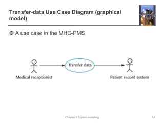
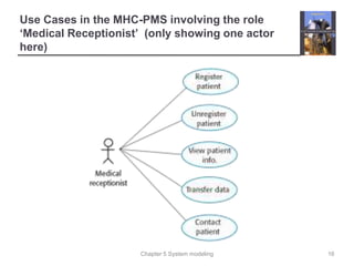
Chapter 5 System modeling
Chapter 5 – System Modeling
Lecture 1
1
Chapter 5 System modeling
Topics covered
 1. Context models
 2. Interaction models
 3. Structural models
 4. Behavioral models
 5. Model-driven engineering
2
Chapter 5 System modeling
Introductory Slides: System modeling
 System modeling is the process of developing abstract models
of a system, with each model presenting a different view or
perspective of that system.
 System modeling has now come to mean representing a
system using some kind of graphical notation, which is now
almost always based on notations in the Unified Modeling
Language (UML).
 System modeling helps the analyst
 to understand the functionality of the system and
 models are used to communicate with customers.
3
Existing and Planned System Models
 Models of the existing system are used during requirements
engineering.
 They help clarify what the existing system does and can be
 used as a basis for discussing its strengths and weaknesses.
 These then lead to requirements for the new system.
 Models of the new system are used during requirements engineering
to help explain the proposed requirements to other system
stakeholders.
 Engineers use these models to discuss design proposals and
 to document the system for implementation.
 In a model-driven engineering process, it is possible to generate a
complete or partial system implementation from the system model.
4
Chapter 5 System modeling
System Perspectives
 An external perspective, where you model the context
or environment of the system.
 An interaction perspective, where you model the
interactions between a system and its environment, or
between the components of a system.
 A structural perspective, where you model the
organization of a system or the structure of the data that
is processed by the system.
 A behavioral perspective, where you model the
dynamic behavior of the system and how it responds to
events.
5
Chapter 5 System modeling
UML Diagram Types
 The System Perspectives (last slide) are modeled with
diagrams
 Activity diagrams, which show the activities involved in a
process or in data processing .
 Use case diagrams, which show the interactions between a
system and its environment.
 Sequence diagrams, which show interactions between actors
and the system and between system components.
 Class diagrams, which show the object classes in the system
and the associations between these classes.
 State diagrams, which show how the system reacts to
internal and external events.
6
Chapter 5 System modeling
1. Context Models
 Context models are used to illustrate the operational
context of a system -
 They show what lies outside the system boundaries.
 Social and organizational concerns may affect the decision
on where to position system boundaries.
 Architectural models show the system and its relationship
with other systems.
7
Chapter 5 System modeling
System Boundaries
 System boundaries are established to define what is inside and
what is outside the system.
 They show other systems that are used or depend on the system being
developed.
 The position of the system boundary has a profound effect on the
system requirements.
 Defining a system boundary is a political judgment
 There may be pressures to develop system boundaries that increase /
decrease the influence or workload of different parts of an organization.
8
Chapter 5 System modeling
The Context of the MHC-PMS
9
Chapter 5 System modeling
Process Perspective
 Context models simply show the other systems in the
environment, not how the system being developed is used in that
environment.
 Process models reveal how the system being developed is used
in broader business processes.
 How it 'works' Detailed.
 UML activity diagrams may be used to define business process
models.
10
Chapter 5 System modeling
Process Model of Involuntary Detention
11
Chapter 5 System modeling
2. Interaction Models
 Modeling user interaction is used to identify user
requirements.
 We see structural connections and dynamic
(behavioral) interactions.
 We do this with graphical models.
 Use case diagrams and sequence diagrams may be
used for interaction modeling.
 These are the most popular modeling mechanisms
12
Chapter 5 System modeling
Use Case Modeling (Interaction Model)
 Use cases were developed originally to support requirements
elicitation and now incorporated into the UML.
 Each use case represents a discrete task that involves
external interaction with a system.
 Actors in a use case may be people, devices, or other
systems.
 Represented diagramatically to provide an overview of the use
case and in a more detailed textual form.
13
Chapter 5 System modeling
Transfer-data Use Case Diagram (graphical
model)
 A use case in the MHC-PMS
14
Chapter 5 System modeling
Tabular Description of the ‘Transfer data’ use-
case
MHC-PMS: Transfer data
Actors Medical receptionist, patient records system (PRS)
Description A receptionist may transfer data from the MHC-PMS to a general
patient record database that is maintained by a health authority.
The information transferred may either be updated personal
information (address, phone number, etc.) or a summary of the
patient’s diagnosis and treatment.
Data Patient’s personal information, treatment summary
Stimulus User command issued by medical receptionist
Response Confirmation that PRS has been updated
Comments The receptionist must have appropriate security permissions to
access the patient information and the PRS. 15
Chapter 5 System modeling
Use Cases in the MHC-PMS involving the role
‘Medical Receptionist’ (only showing one actor
here)
16
Chapter 5 System modeling
Sequence Diagrams (Interaction Model)
 Sequence diagrams are part of the UML and are used to
model the interactions between the actors and the objects
within a system.
 A sequence diagram shows the sequence of interactions that
take place during a particular use case or use case instance.
 The objects and actors involved are listed along the top of the
diagram, with a dotted line drawn vertically from these.
 Interactions between objects are indicated by annotated
arrows.
17
Chapter 5 System modeling
Sequence diagram for View Patient Information
18
Chapter 5 System modeling
Sequence diagram for Transfer Data
19
Chapter 5 System modeling
Key points
 A model is an abstract view of a system that ignores system details.
Complementary system models can be developed to show the
system’s context, interactions, structure and behavior.
 Context models show how a system that is being modeled is
positioned in an environment with other systems and processes.
 Use case diagrams and sequence diagrams are used to describe the
interactions between users and systems in the system being
designed. Use cases describe interactions between a system and
external actors; sequence diagrams add more information to these by
showing interactions between system objects.
20

Chap 5 - System Modeling Part 1.ppt

  • 1.
    Chapter 5 Systemmodeling Chapter 5 – System Modeling Lecture 1 1
  • 2.
    Chapter 5 Systemmodeling Topics covered  1. Context models  2. Interaction models  3. Structural models  4. Behavioral models  5. Model-driven engineering 2
  • 3.
    Chapter 5 Systemmodeling Introductory Slides: System modeling  System modeling is the process of developing abstract models of a system, with each model presenting a different view or perspective of that system.  System modeling has now come to mean representing a system using some kind of graphical notation, which is now almost always based on notations in the Unified Modeling Language (UML).  System modeling helps the analyst  to understand the functionality of the system and  models are used to communicate with customers. 3
  • 4.
    Existing and PlannedSystem Models  Models of the existing system are used during requirements engineering.  They help clarify what the existing system does and can be  used as a basis for discussing its strengths and weaknesses.  These then lead to requirements for the new system.  Models of the new system are used during requirements engineering to help explain the proposed requirements to other system stakeholders.  Engineers use these models to discuss design proposals and  to document the system for implementation.  In a model-driven engineering process, it is possible to generate a complete or partial system implementation from the system model. 4
  • 5.
    Chapter 5 Systemmodeling System Perspectives  An external perspective, where you model the context or environment of the system.  An interaction perspective, where you model the interactions between a system and its environment, or between the components of a system.  A structural perspective, where you model the organization of a system or the structure of the data that is processed by the system.  A behavioral perspective, where you model the dynamic behavior of the system and how it responds to events. 5
  • 6.
    Chapter 5 Systemmodeling UML Diagram Types  The System Perspectives (last slide) are modeled with diagrams  Activity diagrams, which show the activities involved in a process or in data processing .  Use case diagrams, which show the interactions between a system and its environment.  Sequence diagrams, which show interactions between actors and the system and between system components.  Class diagrams, which show the object classes in the system and the associations between these classes.  State diagrams, which show how the system reacts to internal and external events. 6
  • 7.
    Chapter 5 Systemmodeling 1. Context Models  Context models are used to illustrate the operational context of a system -  They show what lies outside the system boundaries.  Social and organizational concerns may affect the decision on where to position system boundaries.  Architectural models show the system and its relationship with other systems. 7
  • 8.
    Chapter 5 Systemmodeling System Boundaries  System boundaries are established to define what is inside and what is outside the system.  They show other systems that are used or depend on the system being developed.  The position of the system boundary has a profound effect on the system requirements.  Defining a system boundary is a political judgment  There may be pressures to develop system boundaries that increase / decrease the influence or workload of different parts of an organization. 8
  • 9.
    Chapter 5 Systemmodeling The Context of the MHC-PMS 9
  • 10.
    Chapter 5 Systemmodeling Process Perspective  Context models simply show the other systems in the environment, not how the system being developed is used in that environment.  Process models reveal how the system being developed is used in broader business processes.  How it 'works' Detailed.  UML activity diagrams may be used to define business process models. 10
  • 11.
    Chapter 5 Systemmodeling Process Model of Involuntary Detention 11
  • 12.
    Chapter 5 Systemmodeling 2. Interaction Models  Modeling user interaction is used to identify user requirements.  We see structural connections and dynamic (behavioral) interactions.  We do this with graphical models.  Use case diagrams and sequence diagrams may be used for interaction modeling.  These are the most popular modeling mechanisms 12
  • 13.
    Chapter 5 Systemmodeling Use Case Modeling (Interaction Model)  Use cases were developed originally to support requirements elicitation and now incorporated into the UML.  Each use case represents a discrete task that involves external interaction with a system.  Actors in a use case may be people, devices, or other systems.  Represented diagramatically to provide an overview of the use case and in a more detailed textual form. 13
  • 14.
    Chapter 5 Systemmodeling Transfer-data Use Case Diagram (graphical model)  A use case in the MHC-PMS 14
  • 15.
    Chapter 5 Systemmodeling Tabular Description of the ‘Transfer data’ use- case MHC-PMS: Transfer data Actors Medical receptionist, patient records system (PRS) Description A receptionist may transfer data from the MHC-PMS to a general patient record database that is maintained by a health authority. The information transferred may either be updated personal information (address, phone number, etc.) or a summary of the patient’s diagnosis and treatment. Data Patient’s personal information, treatment summary Stimulus User command issued by medical receptionist Response Confirmation that PRS has been updated Comments The receptionist must have appropriate security permissions to access the patient information and the PRS. 15
  • 16.
    Chapter 5 Systemmodeling Use Cases in the MHC-PMS involving the role ‘Medical Receptionist’ (only showing one actor here) 16
  • 17.
    Chapter 5 Systemmodeling Sequence Diagrams (Interaction Model)  Sequence diagrams are part of the UML and are used to model the interactions between the actors and the objects within a system.  A sequence diagram shows the sequence of interactions that take place during a particular use case or use case instance.  The objects and actors involved are listed along the top of the diagram, with a dotted line drawn vertically from these.  Interactions between objects are indicated by annotated arrows. 17
  • 18.
    Chapter 5 Systemmodeling Sequence diagram for View Patient Information 18
  • 19.
    Chapter 5 Systemmodeling Sequence diagram for Transfer Data 19
  • 20.
    Chapter 5 Systemmodeling Key points  A model is an abstract view of a system that ignores system details. Complementary system models can be developed to show the system’s context, interactions, structure and behavior.  Context models show how a system that is being modeled is positioned in an environment with other systems and processes.  Use case diagrams and sequence diagrams are used to describe the interactions between users and systems in the system being designed. Use cases describe interactions between a system and external actors; sequence diagrams add more information to these by showing interactions between system objects. 20