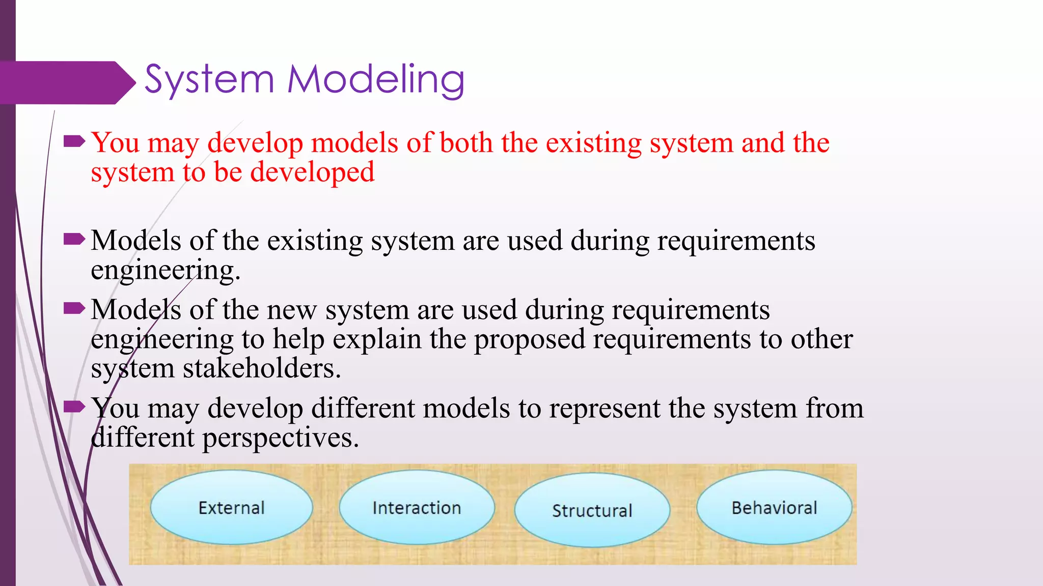
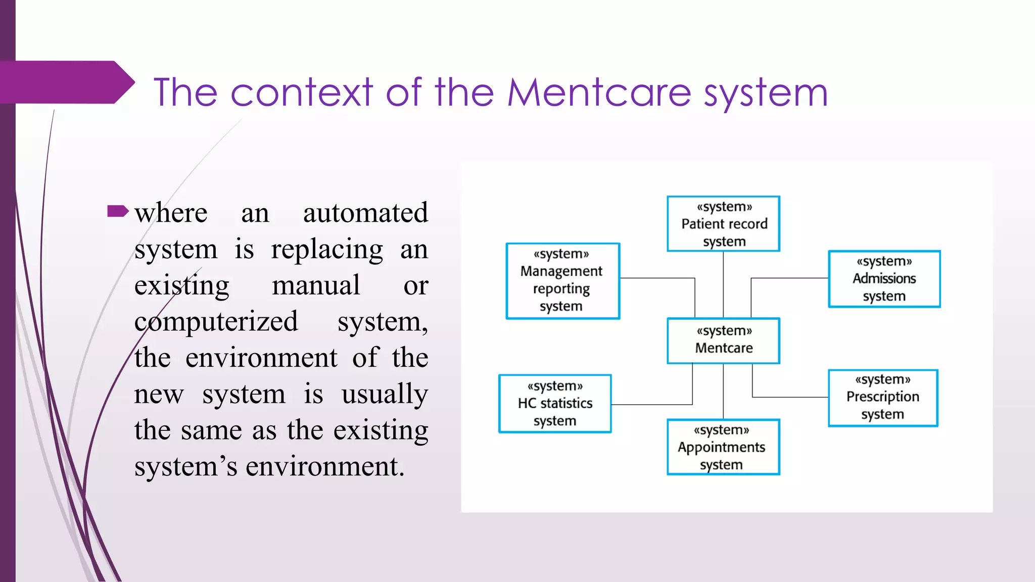
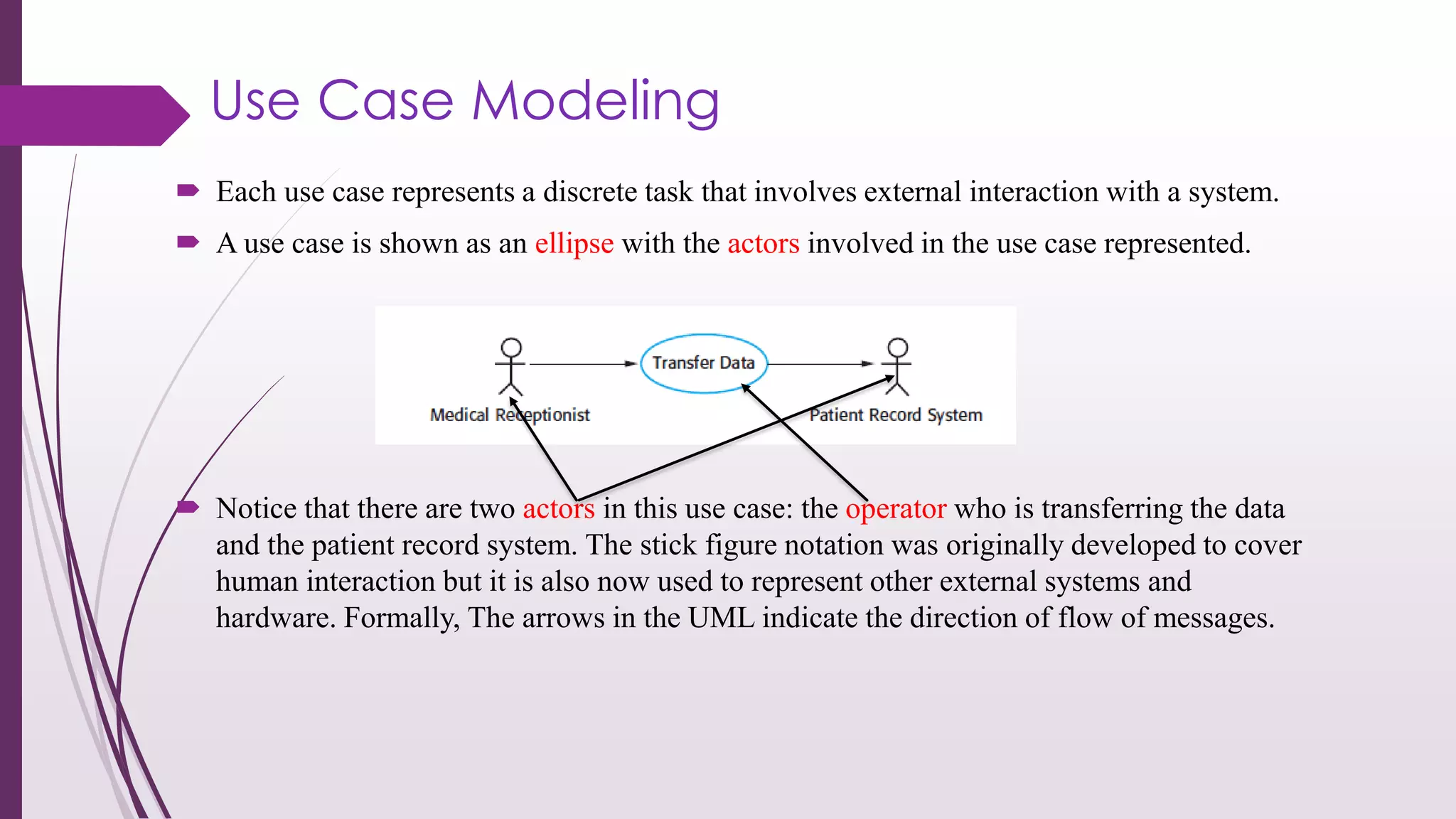
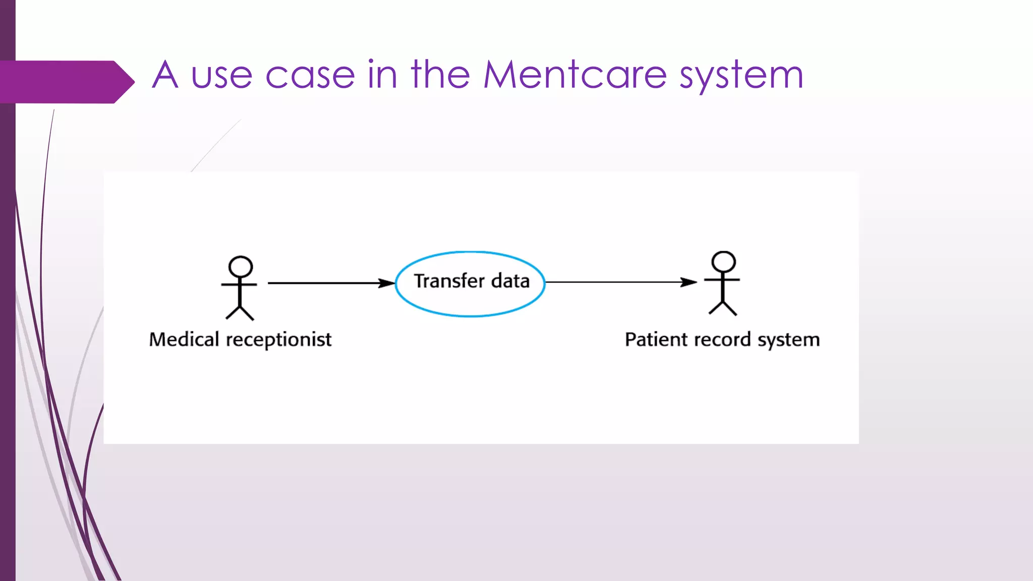
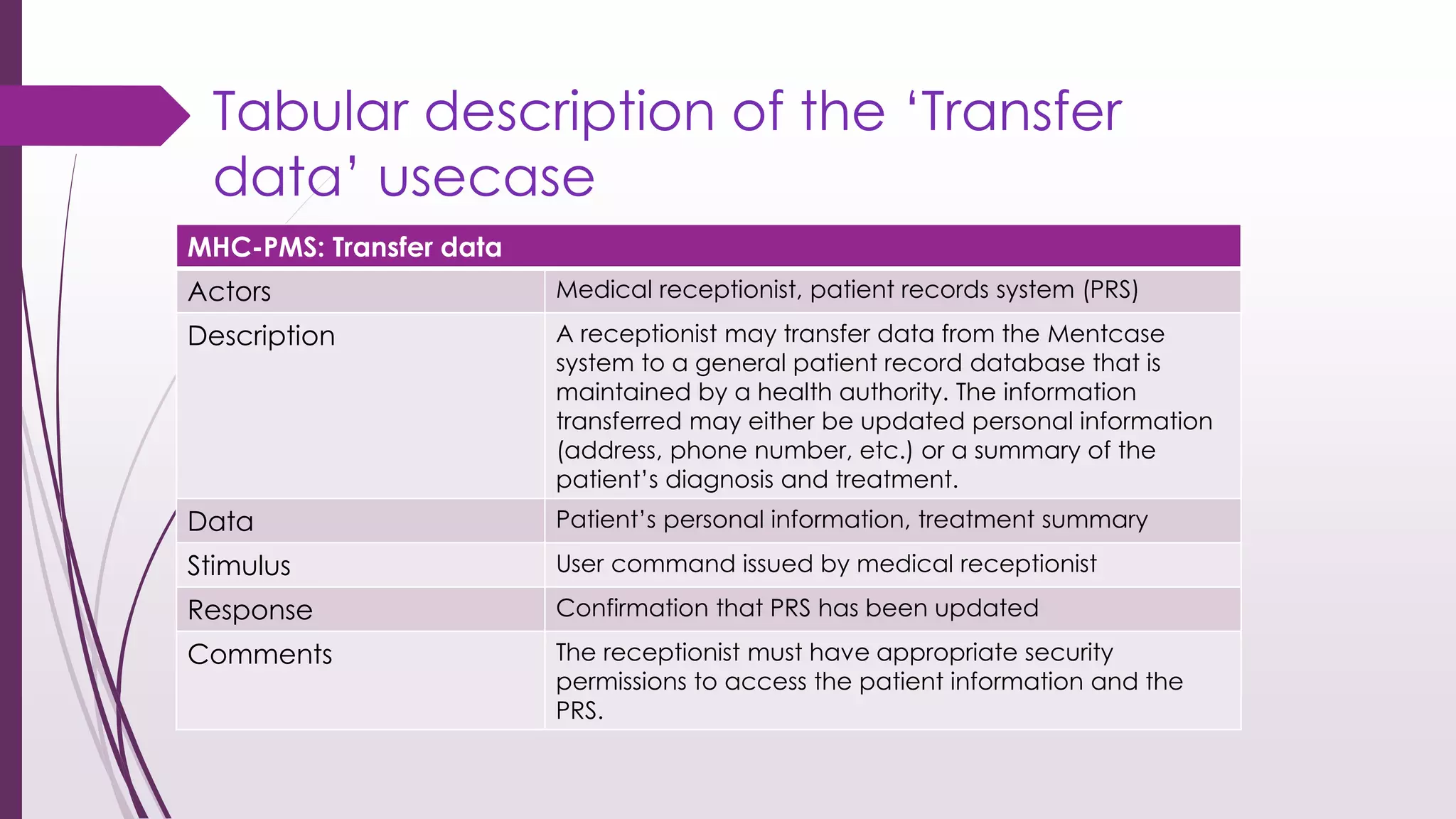
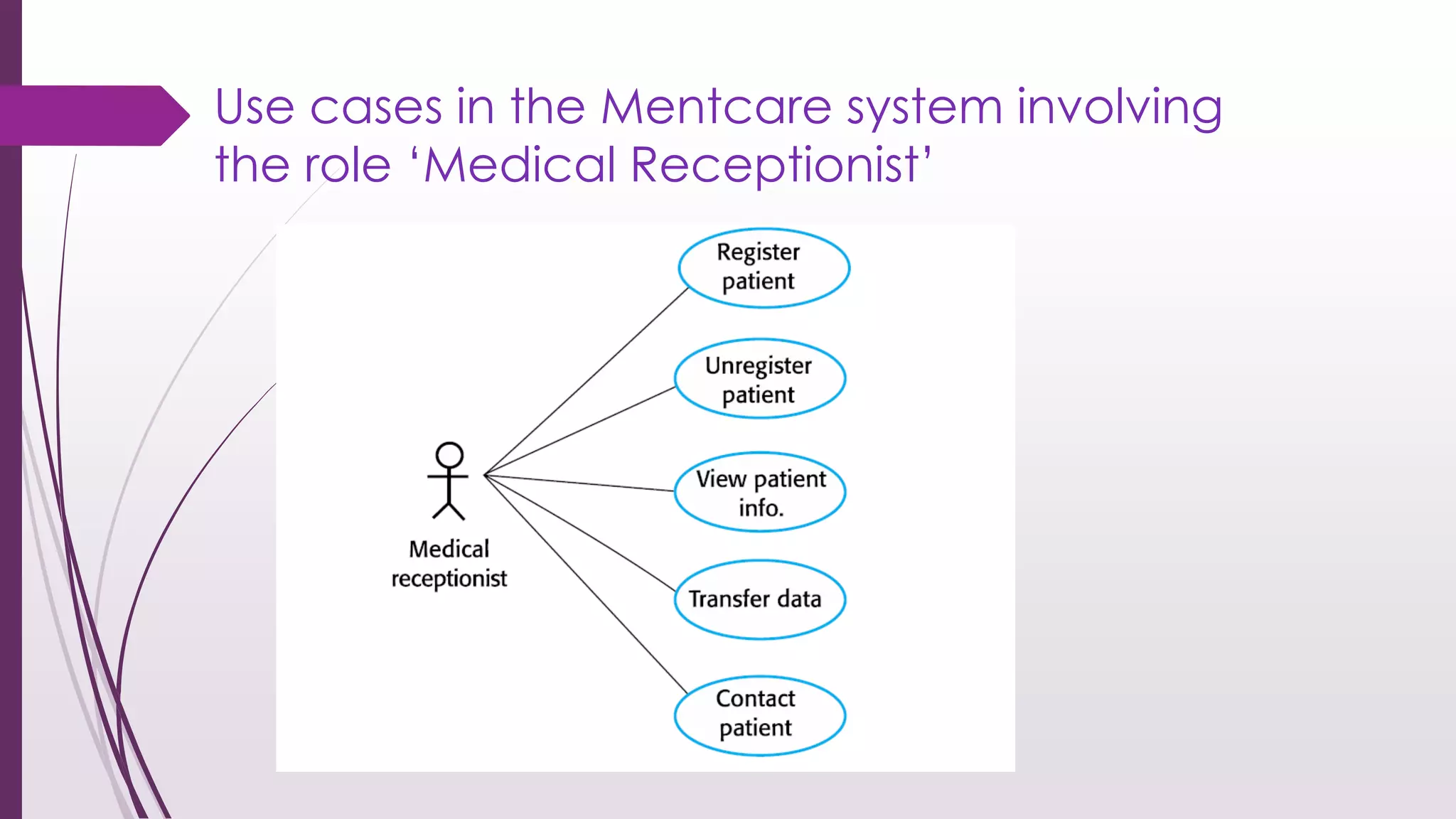
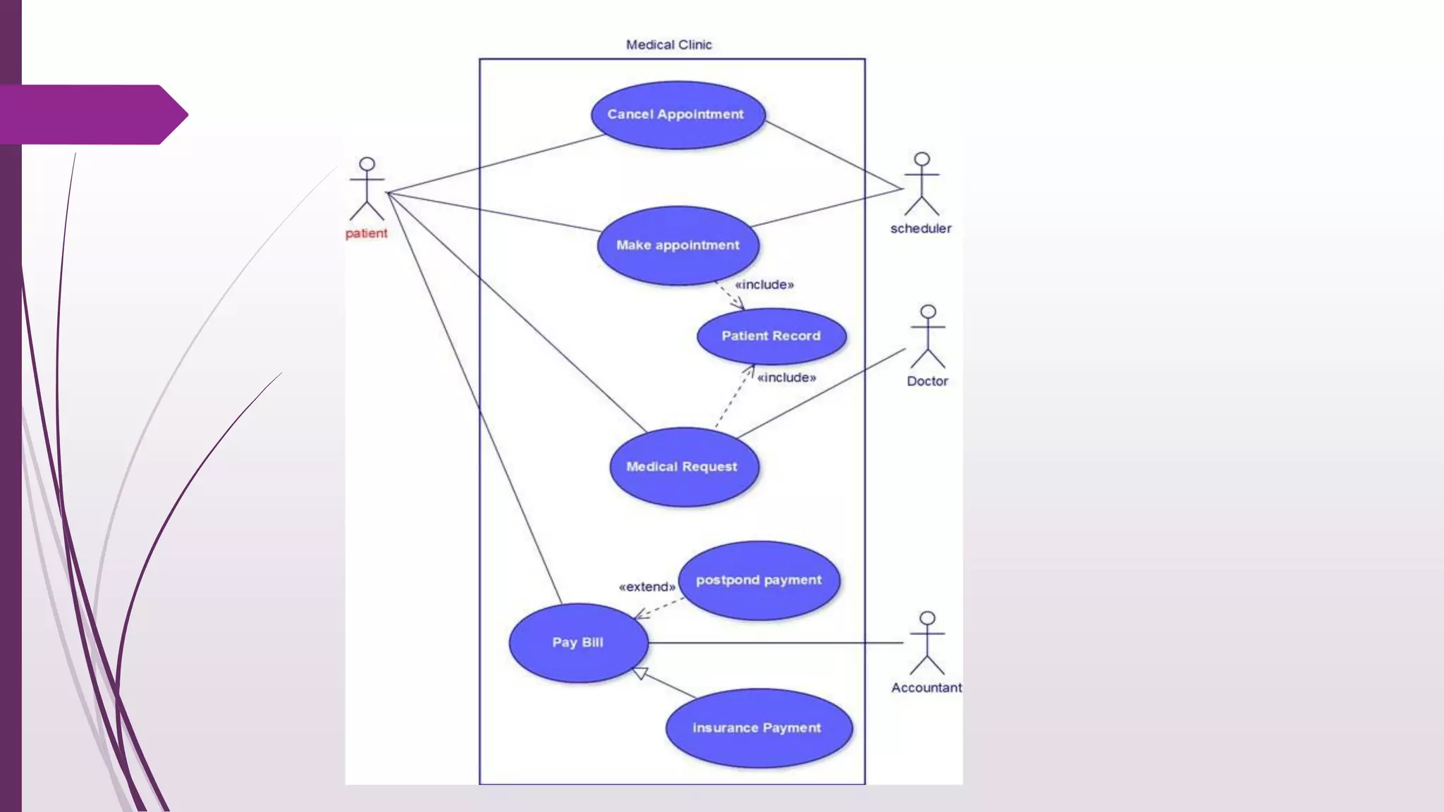
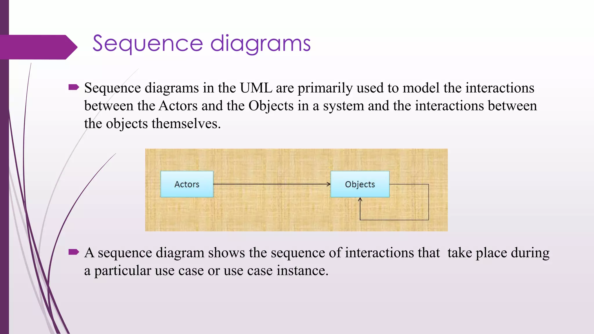
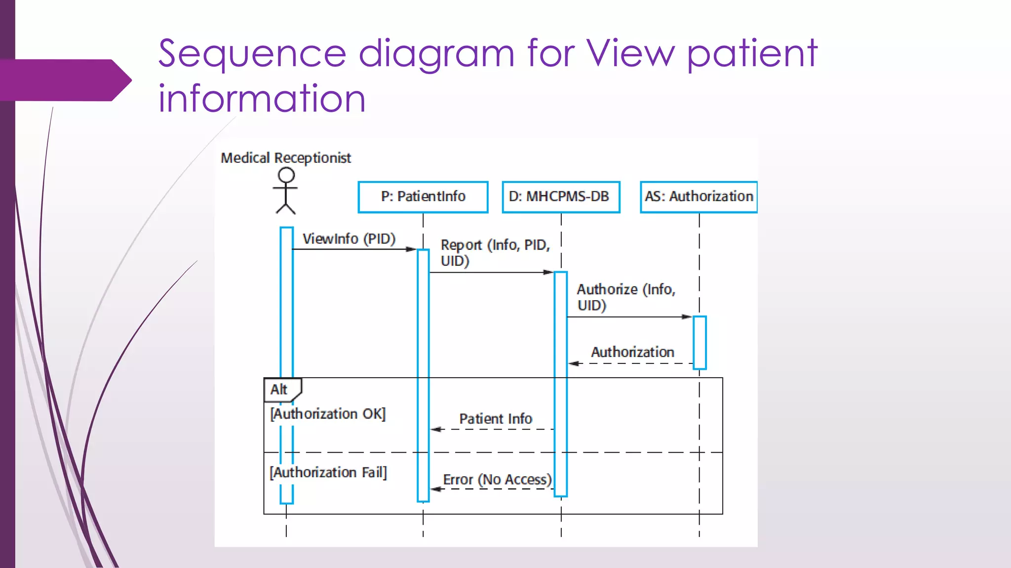
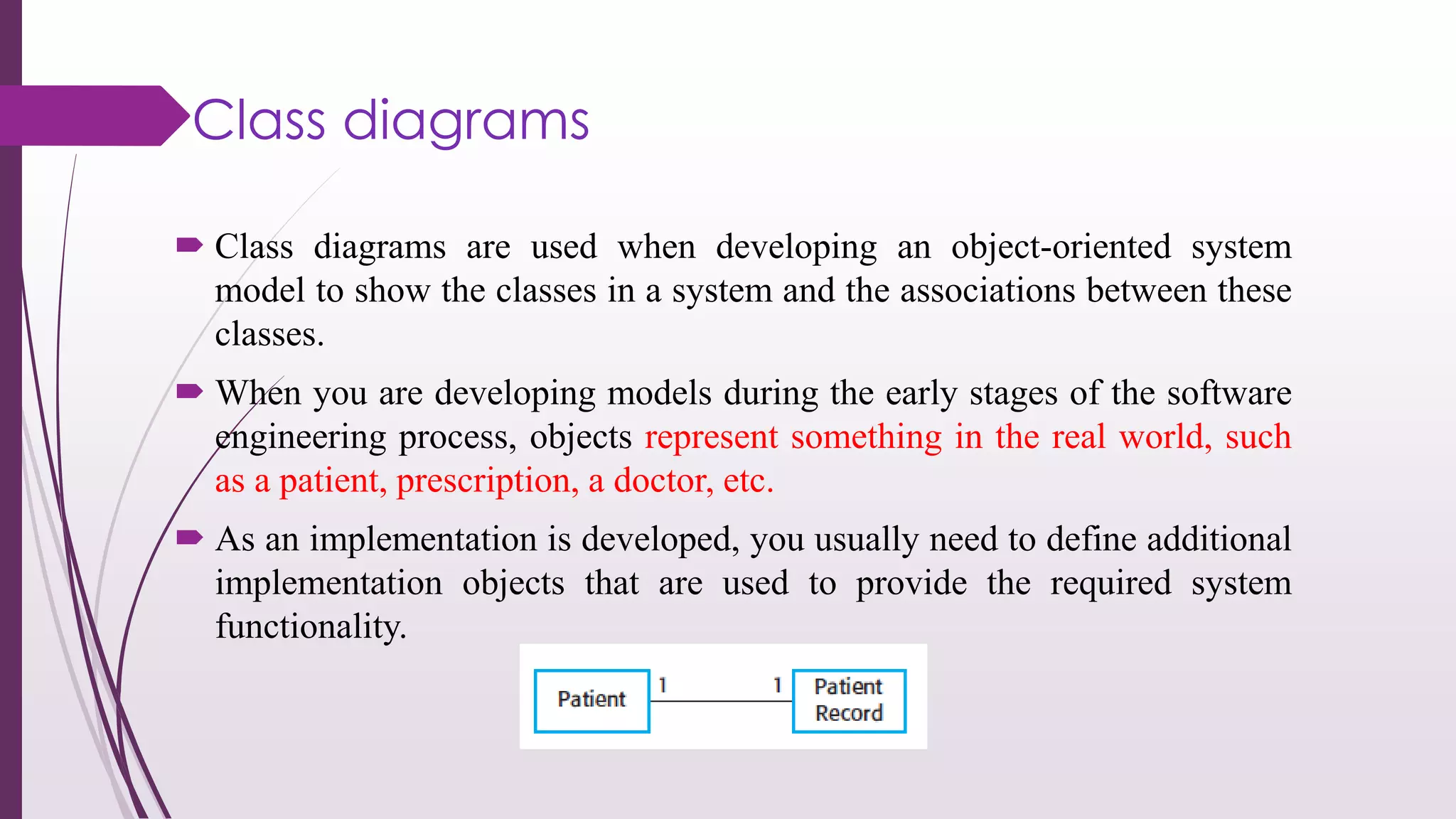
This document discusses system modeling and the Unified Modeling Language (UML). It provides an overview of different types of UML diagrams including class, sequence, use case, state, and activity diagrams. It also discusses modeling concepts such as system boundaries, interactions, and structural models. Specific examples are provided including a use case diagram for a patient data transfer process and a sequence diagram for viewing patient information in a mental healthcare system.
software engineering Chapter 5 System modeling.pptxnada99848
software engineering Ch5 System modeling 10th eddition lan sommerville-software engineering Ch5 System modeling 10th eddition lan sommerville-software engineering Ch5 System modeling 10th eddition lan sommerville-software engineering Ch5 System modeling 10th eddition lan sommerville-software engineering Ch5 System modeling 10th eddition lan sommerville-software engineering Ch5 System modeling 10th eddition lan sommerville-software engineering Ch5 System modeling 10th eddition lan sommerville-software engineering Ch5 System modeling 10th eddition lan sommerville-software engineering Ch5 System modeling 10th eddition lan sommerville-software engineering Ch5 System modeling 10th eddition lan sommerville-software engineering Ch5 System modeling 10th eddition lan sommerville-software engineering Ch5 System modeling 10th eddition lan sommerville-software engineering Ch5 System modeling 10th eddition lan sommerville-software engineering Ch5 System modeling 10th eddition lan sommerville-software engineering Ch5 System modeling 10th eddition lan sommerville-software engineering Ch5 System modeling 10th eddition lan sommerville-software engineering Ch5 System modeling 10th eddition lan sommerville-software engineering Ch5 System modeling 10th eddition lan sommerville-software engineering Ch5 System modeling 10th eddition lan sommerville-software engineering Ch5 System modeling 10th eddition lan sommerville-software engineering Ch5 System modeling 10th eddition lan sommerville-software engineering Ch5 System modeling 10th eddition lan sommerville-software engineering Ch5 System modeling 10th eddition lan sommerville-software engineering Ch5 System modeling 10th eddition lan sommerville-software engineering Ch5 System modeling 10th eddition lan sommerville-software engineering Ch5 System modeling 10th eddition lan sommerville-software engineering Ch5 System modeling 10th eddition lan sommerville-software engineering Ch5 System modeling 10th eddition lan sommerville-software engineering Ch5 System modeling 10th eddition lan sommerville-software engineering Ch5 System modeling 10th eddition lan sommerville-software engineering Ch5 System modeling 10th eddition lan sommerville-software engineering Ch5 System modeling 10th eddition lan sommerville-software engineering Ch5 System modeling 10th eddition lan sommerville-software engineering Ch5 System modeling 10th eddition lan sommerville-software engineering Ch5 System modeling 10th eddition lan sommerville-software engineering Ch5 System modeling 10th eddition lan sommerville-software engineering Ch5 System modeling 10th eddition lan sommerville-software engineering Ch5 System modeling 10th eddition lan sommerville-software engineering Ch5 System modeling 10th eddition lan sommerville-software engineering Ch5 System modeling 10th eddition lan sommerville-software engineering Ch5 System modeling 10th eddition lan sommerville
Course Number
Course Section
Course Name
Project Name (Unit 1 IP)
Student Name
Table of Contents
Introduction 3
Use cases 4
Figure 1: Online order system use case diagram 4
Class Diagram 5
Figure 2: Class diagram 6
Activity diagram 7
Figure 3: Activity diagram 8
Sequence diagram 9
Figure 4: Sequence Diagram 9
References 10
UML Model for Project Introduction
System design is a process that helps to conceptualize the software system requirements into a software implementation. It involves taking the user requirements and using it to define system architecture, interfaces and modules for the system. The most widely used method for software system design today is Object-Oriented analysis and design methods for their reusability and easy way of expressing relationship between system components(Martin, 2011). To be able to efficiently utilize the power of object-oriented analysis and design methods you need to use its standard language, Unified Modeling language (UML). UML is a general purpose modeling language that is used to provide a standard way to visualize the design of a system. UML is rich of modeling notations and methods that are used to create different diagrams to represent structural and behavior information of the system (Wazlawick, 2014). Example of this diagrams include class diagram, use case diagram, deployment diagrams, activity diagram, state, object, and sequence among other.
The diagram in the following sections represents the structural and behavior of the Online ordering system. Use cases
Use case diagram are used to represent a user’s interaction with the system hence showing the relationship between the system and its users. Use cases identify the different actors (users) of the system and the different ways (use cases) they interact with the system. The use case diagram below shows the two main users of the online orders system and how the use the system.
Figure 1: Online order system use case diagramClass Diagram
UML Class diagram are static structure diagram used to describe the structure of software system by showing classes, operations, their attributes and the relationship among them. Classes form the main building block of Object Oriented modeling and hence class diagram help to conceptualize the general structure of the system that can later be translate into programming code. Classes in class diagram represent the main elements in the application to be programmed (Booch, 1994).
The diagram below show the class diagram for the recommend online ordering system. Boxes represent classes. Boxes are supposed to have three compartments to complete the represent class information in full, one for class name, second for class attributes and the third for class operations. The diagram below shows a simple representation of classes. The lines represent links between classes and show the kind of relationship between classes. For example user is generalization for customer and sales. Customer makes o.
Welcome to WIPAC Monthly the magazine brought to you by the LinkedIn Group Water Industry Process Automation & Control.
In this month's edition, along with this month's industry news to celebrate the 13 years since the group was created we have articles including
A case study of the used of Advanced Process Control at the Wastewater Treatment works at Lleida in Spain
A look back on an article on smart wastewater networks in order to see how the industry has measured up in the interim around the adoption of Digital Transformation in the Water Industry.
Explore the innovative world of trenchless pipe repair with our comprehensive guide, "The Benefits and Techniques of Trenchless Pipe Repair." This document delves into the modern methods of repairing underground pipes without the need for extensive excavation, highlighting the numerous advantages and the latest techniques used in the industry.
Learn about the cost savings, reduced environmental impact, and minimal disruption associated with trenchless technology. Discover detailed explanations of popular techniques such as pipe bursting, cured-in-place pipe (CIPP) lining, and directional drilling. Understand how these methods can be applied to various types of infrastructure, from residential plumbing to large-scale municipal systems.
Ideal for homeowners, contractors, engineers, and anyone interested in modern plumbing solutions, this guide provides valuable insights into why trenchless pipe repair is becoming the preferred choice for pipe rehabilitation. Stay informed about the latest advancements and best practices in the field.
Overview of the fundamental roles in Hydropower generation and the components involved in wider Electrical Engineering.
This paper presents the design and construction of hydroelectric dams from the hydrologist’s survey of the valley before construction, all aspects and involved disciplines, fluid dynamics, structural engineering, generation and mains frequency regulation to the very transmission of power through the network in the United Kingdom.
Author: Robbie Edward Sayers
Collaborators and co editors: Charlie Sims and Connor Healey.
(C) 2024 Robbie E. Sayers
About
Indigenized remote control interface card suitable for MAFI system CCR equipment. Compatible for IDM8000 CCR. Backplane mounted serial and TCP/Ethernet communication module for CCR remote access. IDM 8000 CCR remote control on serial and TCP protocol.
• Remote control: Parallel or serial interface.
• Compatible with MAFI CCR system.
• Compatible with IDM8000 CCR.
• Compatible with Backplane mount serial communication.
• Compatible with commercial and Defence aviation CCR system.
• Remote control system for accessing CCR and allied system over serial or TCP.
• Indigenized local Support/presence in India.
• Easy in configuration using DIP switches.
Technical Specifications
Indigenized remote control interface card suitable for MAFI system CCR equipment. Compatible for IDM8000 CCR. Backplane mounted serial and TCP/Ethernet communication module for CCR remote access. IDM 8000 CCR remote control on serial and TCP protocol.
Key Features
Indigenized remote control interface card suitable for MAFI system CCR equipment. Compatible for IDM8000 CCR. Backplane mounted serial and TCP/Ethernet communication module for CCR remote access. IDM 8000 CCR remote control on serial and TCP protocol.
• Remote control: Parallel or serial interface
• Compatible with MAFI CCR system
• Copatiable with IDM8000 CCR
• Compatible with Backplane mount serial communication.
• Compatible with commercial and Defence aviation CCR system.
• Remote control system for accessing CCR and allied system over serial or TCP.
• Indigenized local Support/presence in India.
Application
• Remote control: Parallel or serial interface.
• Compatible with MAFI CCR system.
• Compatible with IDM8000 CCR.
• Compatible with Backplane mount serial communication.
• Compatible with commercial and Defence aviation CCR system.
• Remote control system for accessing CCR and allied system over serial or TCP.
• Indigenized local Support/presence in India.
• Easy in configuration using DIP switches.
NO1 Uk best vashikaran specialist in delhi vashikaran baba near me online vas...Amil Baba Dawood bangali
Contact with Dawood Bhai Just call on +92322-6382012 and we'll help you. We'll solve all your problems within 12 to 24 hours and with 101% guarantee and with astrology systematic. If you want to take any personal or professional advice then also you can call us on +92322-6382012 , ONLINE LOVE PROBLEM & Other all types of Daily Life Problem's.Then CALL or WHATSAPP us on +92322-6382012 and Get all these problems solutions here by Amil Baba DAWOOD BANGALI
#vashikaranspecialist #astrologer #palmistry #amliyaat #taweez #manpasandshadi #horoscope #spiritual #lovelife #lovespell #marriagespell#aamilbabainpakistan #amilbabainkarachi #powerfullblackmagicspell #kalajadumantarspecialist #realamilbaba #AmilbabainPakistan #astrologerincanada #astrologerindubai #lovespellsmaster #kalajaduspecialist #lovespellsthatwork #aamilbabainlahore#blackmagicformarriage #aamilbaba #kalajadu #kalailam #taweez #wazifaexpert #jadumantar #vashikaranspecialist #astrologer #palmistry #amliyaat #taweez #manpasandshadi #horoscope #spiritual #lovelife #lovespell #marriagespell#aamilbabainpakistan #amilbabainkarachi #powerfullblackmagicspell #kalajadumantarspecialist #realamilbaba #AmilbabainPakistan #astrologerincanada #astrologerindubai #lovespellsmaster #kalajaduspecialist #lovespellsthatwork #aamilbabainlahore #blackmagicforlove #blackmagicformarriage #aamilbaba #kalajadu #kalailam #taweez #wazifaexpert #jadumantar #vashikaranspecialist #astrologer #palmistry #amliyaat #taweez #manpasandshadi #horoscope #spiritual #lovelife #lovespell #marriagespell#aamilbabainpakistan #amilbabainkarachi #powerfullblackmagicspell #kalajadumantarspecialist #realamilbaba #AmilbabainPakistan #astrologerincanada #astrologerindubai #lovespellsmaster #kalajaduspecialist #lovespellsthatwork #aamilbabainlahore #Amilbabainuk #amilbabainspain #amilbabaindubai #Amilbabainnorway #amilbabainkrachi #amilbabainlahore #amilbabaingujranwalan #amilbabainislamabad
Final project report on grocery store management system..pdfKamal Acharya
In today’s fast-changing business environment, it’s extremely important to be able to respond to client needs in the most effective and timely manner. If your customers wish to see your business online and have instant access to your products or services.
Online Grocery Store is an e-commerce website, which retails various grocery products. This project allows viewing various products available enables registered users to purchase desired products instantly using Paytm, UPI payment processor (Instant Pay) and also can place order by using Cash on Delivery (Pay Later) option. This project provides an easy access to Administrators and Managers to view orders placed using Pay Later and Instant Pay options.
In order to develop an e-commerce website, a number of Technologies must be studied and understood. These include multi-tiered architecture, server and client-side scripting techniques, implementation technologies, programming language (such as PHP, HTML, CSS, JavaScript) and MySQL relational databases. This is a project with the objective to develop a basic website where a consumer is provided with a shopping cart website and also to know about the technologies used to develop such a website.
This document will discuss each of the underlying technologies to create and implement an e- commerce website.
Saudi Arabia stands as a titan in the global energy landscape, renowned for its abundant oil and gas resources. It's the largest exporter of petroleum and holds some of the world's most significant reserves. Let's delve into the top 10 oil and gas projects shaping Saudi Arabia's energy future in 2024.
2. System modeling is the process of developing abstract models of
a system, with each model presenting a different view or
perspective of that system.
System modeling has now come to mean representing a system
using some kind of graphical notation, which is now almost
always based on notations in the Unified Modeling Language
(UML).
System modelling helps the analyst to understand the
functionality of the system and models are used to communicate
with customers.
Introduction
3. The Unified Modeling Language (UML) is a general purpose,
developmental, modeling language in the field of software
engineering, that is intended to provide a standard way to visualize
the design of a system.
The elements are like components which can be associated
in different ways to make a complete UML pictures which is known
as diagram. So it is very important to understand the different
diagrams to implement the knowledge in real life systems.
Unified Modeling Language
4. UML diagram types
Activity diagrams, which show the activities involved in a
process or in data processing .
Use case diagrams, which show the interactions between a
system and its environment.
Sequence diagrams, which show interactions between actors
and the system and between system components.
Class diagrams, which show the object classes in the system
and the associations between these classes.
State diagrams, which show how the system reacts to internal
and external events.
5. System Modeling
You may develop models of both the existing system and the
system to be developed
Models of the existing system are used during requirements
engineering.
Models of the new system are used during requirements
engineering to help explain the proposed requirements to other
system stakeholders.
You may develop different models to represent the system from
different perspectives.
6. System Modeling
UML Five Diagram Types
1. Activity diagrams
2. Use case diagrams
3. Sequence diagrams
4. Class diagrams
5. State diagrams
7. Context Models
Context models are used to illustrate the operational context of a
system - they show what lies outside the system boundaries.
Social and organizational concerns may affect the decision on
where to position system boundaries.
Architectural models show the system and its relationship with
other systems.
8. System boundaries
System boundaries are established to define what is inside and
what is outside the system.
They show other systems that are used or depend on the system
being developed.
The position of the system boundary has a profound effect on
the system requirements.
Defining a system boundary is a political judgment
There may be pressures to develop system boundaries that
increase / decrease the influence or workload of different parts
of an organization.
9. The context of the Mentcare system
where an automated
system is replacing an
existing manual or
computerized system,
the environment of the
new system is usually
the same as the existing
system’s environment.
10. Interaction models
All systems involve interaction of some kind. This can be user interaction,
which involves user inputs and outputs, interaction between the system being
developed and other systems or interaction between the components of the
system.
1. External Interaction
2.Internal Interaction
Use case modeling, which is mostly used to model interactions between a system
and external actors (users or other systems).
Sequence diagrams, which are used to model interactions between system
components, although external agents may also be included.
Note:-
Use case models and sequence diagrams present interaction at different levels of
detail and so may be used together.
11. Use Case Modeling
Each use case represents a discrete task that involves external interaction with a system.
A use case is shown as an ellipse with the actors involved in the use case represented.
Notice that there are two actors in this use case: the operator who is transferring the data
and the patient record system. The stick figure notation was originally developed to cover
human interaction but it is also now used to represent other external systems and
hardware. Formally, The arrows in the UML indicate the direction of flow of messages.
13. Tabular description of the ‘Transfer
data’ usecase
MHC-PMS: Transfer data
Actors Medical receptionist, patient records system (PRS)
Description A receptionist may transfer data from the Mentcase
system to a general patient record database that is
maintained by a health authority. The information
transferred may either be updated personal information
(address, phone number, etc.) or a summary of the
patient’s diagnosis and treatment.
Data Patient’s personal information, treatment summary
Stimulus User command issued by medical receptionist
Response Confirmation that PRS has been updated
Comments The receptionist must have appropriate security
permissions to access the patient information and the
PRS.
14. Use cases in the Mentcare system involving
the role ‘Medical Receptionist’
15.
16. Sequence diagrams
Sequence diagrams in the UML are primarily used to model the interactions
between the Actors and the Objects in a system and the interactions between
the objects themselves.
A sequence diagram shows the sequence of interactions that take place during
a particular use case or use case instance.
17. Mechanisms
The objects and actors involved are listed along the top of the
diagram, with a dotted line drawn vertically from these.
Interactions between objects are indicated by annotated arrows.
The rectangle on the dotted lines indicates the lifeline of the object
concerned (i.e., the time that object instance is involved in the
computation).
You read the sequence of interactions from top to bottom. The
annotations on the arrows indicate the calls to the objects, their
parameters, and the return values.
19. Structural Models
Structural models of software display the organization of a system in
terms of the components that make up that system and their
relationships.
Structural models:
1.Static Model
2.Dynamic Model
20. Class diagrams
Class diagrams are used when developing an object-oriented system
model to show the classes in a system and the associations between these
classes.
When you are developing models during the early stages of the software
engineering process, objects represent something in the real world, such
as a patient, prescription, a doctor, etc.
As an implementation is developed, you usually need to define additional
implementation objects that are used to provide the required system
functionality.