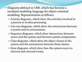
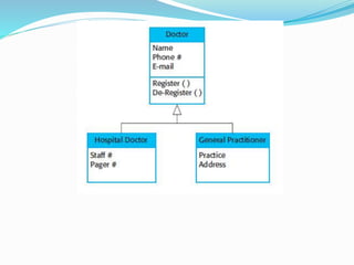
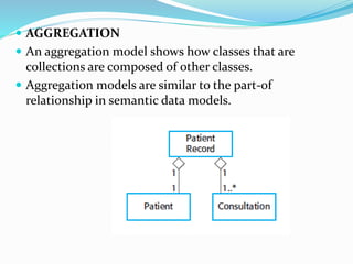
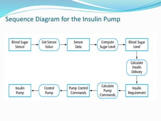
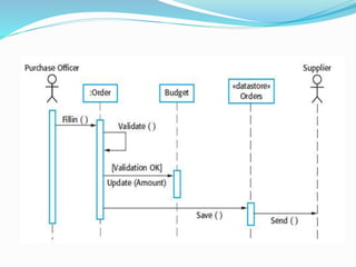
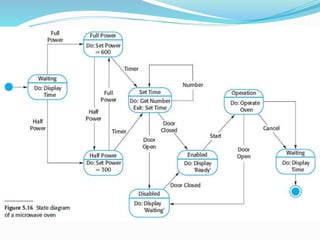
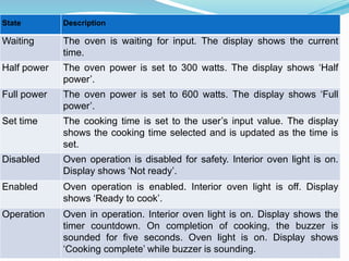
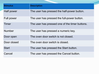
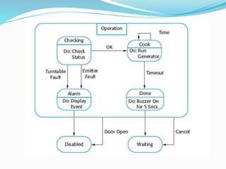
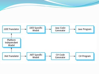
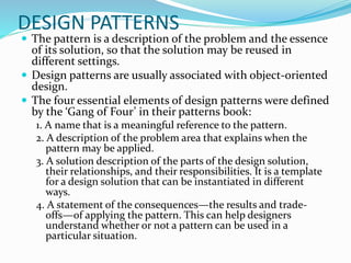
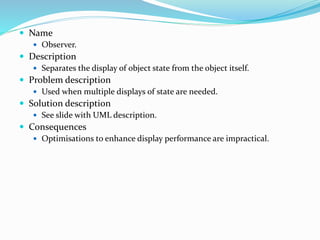
2. System modeling is the process of developing abstract
models of a system, with each model presenting a
different view or perspective of that system.
System modeling has generally come to mean
representing the system using some kind of graphical
notation, which is now almost always based on
notations in the Unified Modeling Language (UML).
Models are used during the requirements engineering
process to help derive the requirements for a system.
During the design process to describe the system to
engineers implementing the system .
After implementation to document the system’s
structure and operation.
3. You may develop models of both the existing system and
the system to be developed:
Models of the existing system are used during requirements
engineering. They help clarify what the existing system does
and can be used as a basis for discussing its strengths and
weaknesses. These then lead to requirements for the new
system.
Models of the new system are used during requirements
engineering to help explain the proposed requirements to
other system stakeholders. Engineers use these models to
discuss design proposals and to document the system for
implementation. In a model-driven engineering process, it is
possible to generate a complete or partial system
implementation from the system model.
4. A model is an abstraction of the system being studied
rather than an alternative representation of that
system. An abstraction deliberately simplifies and
picks out the most salient characteristics.
Different models to represent the system from
different perspectives. For example:
An external perspective, where you model the context or
environment of the system.
An interaction perspective where you model the
interactions between a system and its environment or
between the components of a system.
A structural perspective, where you model the
organization of a system or the structure of the data that
is processed by the system.
A behavioral perspective, where you model the dynamic
behavior of the system and how it responds to events.
5. Diagrams defined in UML which has become a
standard modeling language for object-oriented
modeling. Representation as follows:
Activity diagrams, which show the activities involved in
a process or in data processing.
Use case diagrams, which show the interactions between
a system and its environment.
Sequence diagrams, which show interactions between
actors and the system and between system components.
Class diagrams, which show the object classes in the
system and the associations between these classes.
State diagrams, which show how the system reacts to
internal and external events.
6. Context model
At an early stage in the specification of a system, you
should decide on the system boundaries.
This involves working with system stakeholders to decide
what functionality should be included in the system and
what is provided by the system’s environment.
Look at possible overlaps in functionality with existing
systems and decide where new functionality should be
implemented.
Social and organizational concerns may mean that the
position of a system boundary may be determined by non-
technical factors.
7. Context models normally show that the environment
includes several other automated systems. However, they
do not show the types of relationships between the systems
in the environment and the system that is being specified
8. Activity diagrams are intended to show the activities that make up a
system process and the flow of control from one activity to another.
9. Interaction Model
All systems involve interaction of some kind. Involves user
inputs and outputs, interaction between the system being
developed and other systems or interaction between the
components of the system.
Helps to identify user requirements. Modeling system to
system interaction highlights the communication problems
that may arise.
Helps us understand if a proposed system structure is likely to
deliver the required system performance and dependability.
Two related approaches to interaction modeling:
Use case modeling, used to model interactions between a
system and external actors .
Sequence diagrams, used to model interactions between
system components, although external agents may also be
included.
10. Use case modeling
Use cases were developed originally to support
requirements elicitation and now incorporated into the
UML.
Each use case represents a discrete task that involves
external interaction with a system.
Actors in a use case may be people or other systems.
Represented diagrammatically to provide an overview of
the use case and in a more detailed textual form.
13. Sequence Diagrams
Sequence diagrams are part of the UML and are used to
model the interactions between the actors and the
objects within a system.
A sequence diagram shows the sequence of interactions
that take place during a particular use case or use case
instance.
The objects and actors involved are listed along the top
of the diagram, with a dotted line drawn vertically from
these.
Interactions between objects are indicated by annotated
arrows.
16. STRUCTURAL MODELS
Structural models of software display the organization
of a system in terms of the components that make up
that system and their relationships.
Structural models may be static models, which show
the structure of the system design, or dynamic models,
which show the organization of the system when it is
executing.
You create structural models of a system when you are
discussing and designing the system architecture.
17. CLASS DIAGRAM
Class diagrams are used when developing an object-
oriented system model to show the classes in a system
and the associations between these classes.
An object class can be thought of as a general definition
of one kind of system object.
An association is a link between classes that indicates
that there is some relationship between these classes.
When you are developing models during the early stages
of the software engineering process, objects represent
something in the real world, such as a patient, a
prescription, doctor, etc.
19. GENERALIZATION
Generalization is an everyday technique that we use to
manage complexity.
Rather than learn the detailed characteristics of every entity
that we experience, we place these entities in more general
classes (animals, cars, houses, etc.) and learn the
characteristics of these classes.
This allows us to infer that different members of these classes
have some common characteristics e.g. squirrels and rats are
rodents.
In object-oriented languages, such as Java, generalization is
implemented using the class inheritance mechanisms built
into the language.
In a generalization, the attributes and operations associated
with higher-level classes are also associated with the lower-
level classes.
The lower-level classes are subclasses inherit the attributes
and operations from their super classes. These lower-level
classes then add more specific attributes and operations.
20.
21.
22. AGGREGATION
An aggregation model shows how classes that are
collections are composed of other classes.
Aggregation models are similar to the part-of
relationship in semantic data models.
23. BEHAVIORAL MODELS
Behavioral models are models of the dynamic behavior
of a system as it is executing. They show what happens
or what is supposed to happen when a system
responds to a stimulus from its environment.
You can think of these stimuli as being of two types:
Data Some data arrives that has to be processed by the
system.
Events Some event happens that triggers system
processing. Events may have associated data, although
this is not always the case.
24. DATA DRIVEN MODELING
Many business systems are data-processing systems that are
primarily driven by data. They are controlled by the data
input to the system, with relatively little external event
processing.
Data-driven models show the sequence of actions involved in
processing input data and generating an associated output.
They are particularly useful during the analysis of
requirements as they can be used to show end-to-end
processing in a system.
They are represented using the data-flow diagrams or the
sequence diagrams.
Sequence diagrams highlight objects in a system where as
data flow diagrams highlight the functions.
27. EVENT DRIVEN MODELING
Event-driven modeling shows how a system responds
to external and internal events.
It is based on the assumption that a system has a finite
number of states and that events (stimuli) may cause a
transition from one state to another
The UML supports event-based modeling using state
diagrams .
State diagrams show system states and events that
cause transitions from one state to another
28.
29. State Description
Waiting The oven is waiting for input. The display shows the current
time.
Half power The oven power is set to 300 watts. The display shows ‘Half
power’.
Full power The oven power is set to 600 watts. The display shows ‘Full
power’.
Set time The cooking time is set to the user’s input value. The display
shows the cooking time selected and is updated as the time is
set.
Disabled Oven operation is disabled for safety. Interior oven light is on.
Display shows ‘Not ready’.
Enabled Oven operation is enabled. Interior oven light is off. Display
shows ‘Ready to cook’.
Operation Oven in operation. Interior oven light is on. Display shows the
timer countdown. On completion of cooking, the buzzer is
sounded for five seconds. Oven light is on. Display shows
‘Cooking complete’ while buzzer is sounding.
30. Stimulus Description
Half power The user has pressed the half-power button.
Full power The user has pressed the full-power button.
Timer The user has pressed one of the timer buttons.
Number The user has pressed a numeric key.
Door open The oven door switch is not closed.
Door closed The oven door switch is closed.
Start The user has pressed the Start button.
Cancel The user has pressed the Cancel button.
31.
32. Model-Driven architecture
Model-driven engineering (MDE) is an approach to
software development where models rather than programs
are the principal outputs of the development process.
The programs that execute on a hardware/software
platform are then generated automatically from the
models.
Proponents of MDE argue that this raises the level of
abstraction in software engineering so that engineers no
longer have to be concerned with programming language
details or the specifics of execution platforms.
33. Model-driven engineering is still at an early stage of
development, and it is unclear whether or not it will
have a significant effect on software engineering
practice.
Pros
Allows systems to be considered at higher levels of
abstraction
Generating code automatically means that it is cheaper
to adapt systems to new platforms.
Cons
Models for abstraction and not necessarily right for
implementation.
Savings from generating code may be outweighed by the
costs of developing translators for new platforms.
34. Model-driven architecture (MDA) was the precursor of
more general model-driven engineering
MDA is a model-focused approach to software design
and implementation that uses a subset of UML models
to describe a system.
Models at different levels of abstraction are created.
From a high-level, platform independent model, it is
possible, in principle, to generate a working program
without manual intervention.
35. Types of Model
A computation independent model (CIM)
These model the important domain abstractions used in
a system. CIMs are sometimes called domain models.
A platform independent model (PIM)
These model the operation of the system without
reference to its implementation. The PIM is usually
described using UML models that show the static
system structure and how it responds to external and
internal events.
Platform specific models (PSM)
These are transformations of the platform-independent
model with a separate PSM for each application
platform. In principle, there may be layers of PSM, with
each layer adding some platform-specific detail.
36.
37.
38. Executable UML
The fundamental notion behind model-driven
engineering is that completely automated
transformation of models to code should be possible.
This is possible using a subset of UML 2, called
Executable UML or xUML.
UML was designed as a language for supporting and
documenting software design, not as a programming
language.
39. Three key model types:
Domain models identify the principal concerns in the
system. These are defined using UML class diagrams
that include objects, attributes, and associations.
Class models, in which classes are defined, along with
their attributes and operations.
State models, in which a state diagram is associated
with each class and is used to describe the lifecycle of
the class.
41. Software design and implementation is the stage in the
software engineering process at which an executable
software system is developed.
Software design is a creative activity in which you
identify software components and their relationships,
based on a customer’s requirements.
Implementation is the process of realizing the design
as a program.
One of the most important implementation decisions
that has to be made at an early stage of a software
project is whether or not you should buy or build the
application software.
42. Object-oriented design using the UML
An object-oriented system is made up of interacting
objects that maintain their own local state and provide
operations on that state.
Object-oriented design processes involve designing
object classes and the relationships between these
classes.
These classes define the objects in the system and their
interactions
Objects include both data and operations to manipulate
that data.
43. To develop a system design from concept to detailed,
object-oriented design, there are several things that
you need:
1. Understand and define the context and the external
interactions with the system.
2. Design the system architecture
3. Identify the principal objects in the system.
4. Develop design models.
5. Specify interfaces.
44. System context and interactions
The first stage in any software design process is to
develop an understanding of the relationships between
the software that is being designed and its external
environment.
Setting the system boundaries helps you decide what
features are implemented in the system being designed
and what features are in other associated systems. It
provides two views:
1. A system context model is a structural model that
demonstrates the other systems in the environment of
the system being developed.
2. An interaction model is a dynamic model that shows
how the system interacts with its environment as it is
used.
45.
46.
47. Architectural design
Once interactions between the system and its
environment have been understood, you use this
information for designing the system architecture.
You identify the major components that make up the
system and their interactions, and then may organize
the components using an architectural pattern such as
a layered or client-server model.
The weather station is composed of independent
subsystems that communicate by broadcasting
messages on a common infrastructure.
48.
49. Object Class Identification
The use case description helps to identify the objects
and operation in the system.
Various approaches are:
Use a grammatical approach based on a natural language
description of the system (used in Hood OOD method).
Base the identification on tangible things in the application
domain.
Use a scenario-based analysis. The objects, attributes and
methods in each scenario are identified.
50.
51. Design Models
Design models show the objects and object classes and
relationships between these entities.
An important step in the design process, is to decide on
the design models that you need and the level of detail
required in these models.
The UML supports 13 different types of models.
When you use the UML to develop a design, you will
normally develop two kinds of design model:
Static models describe the static structure of the system in
terms of object classes and relationships.
Dynamic models describe the dynamic interactions between
objects.
52. Three models that are particularly useful for adding
detail to use case and architectural models:
Subsystem models that show logical groupings of
objects into coherent subsystems. They are static model
Sequence models that show the sequence of object
interactions. They are dynamic model.
State machine models that show how individual objects
change their state in response to events. They are
dynamic model.
53.
54.
55.
56. Interface Specification
An important part of any design process is the
specification of the interfaces between the components
in the design.
specify interfaces so that objects and subsystems can be
designed in parallel.
Interface design is concerned with specifying the detail
of the interface to an object or to a group of objects.
Interfaces can be specified in the UML using the same
notation as a class diagram.
57. DESIGN PATTERNS
The pattern is a description of the problem and the essence
of its solution, so that the solution may be reused in
different settings.
Design patterns are usually associated with object-oriented
design.
The four essential elements of design patterns were defined
by the ‘Gang of Four’ in their patterns book:
1. A name that is a meaningful reference to the pattern.
2. A description of the problem area that explains when the
pattern may be applied.
3. A solution description of the parts of the design solution,
their relationships, and their responsibilities. It is a template
for a design solution that can be instantiated in different
ways.
4. A statement of the consequences—the results and trade-
offs—of applying the pattern. This can help designers
understand whether or not a pattern can be used in a
particular situation.
58. Name
Observer.
Description
Separates the display of object state from the object itself.
Problem description
Used when multiple displays of state are needed.
Solution description
See slide with UML description.
Consequences
Optimisations to enhance display performance are impractical.
59.
60.
61. IMPLEMENTATION ISSUES
Aspects of implementation that are particularly
important to software engineering are as follows:
Reuse Most modern software is constructed by reusing
existing components or systems. When you are developing
software, you should make as much use as possible of existing
code.
Configuration management During the development
process, you have to keep track of the many different versions
of each software component in a configuration management
system.
Host-target development Production software does not
usually execute on the same computer as the software
development environment. Rather, you develop it on one
computer (the host system) and execute it on a separate
computer (the target system).
62. Reuse
From the 1960s to the 1990s, most new software was
developed from scratch, by writing all code in a high-
level programming language.
Costs and schedule pressure mean that this approach
became increasingly unviable, especially for commercial
and Internet-based systems.
An approach to development based around the reuse of
existing software emerged and is now generally used for
business and scientific software.
63. Software reuse is possible at a number of different
levels:
The abstraction level
At this level, you don’t reuse software directly but use
knowledge of successful abstractions in the design of your
software.
The object level
At this level, you directly reuse objects from a library rather
than writing the code yourself.
The component level
Components are collections of objects and object classes that
you reuse in application systems.
The system level
At this level, you reuse entire application systems.
64. Costs associated with reuse are as follows:
The costs of the time spent in looking for software to
reuse and assessing whether or not it meets your needs.
Where applicable, the costs of buying the reusable
software. For large off-the-shelf systems, these costs can
be very high.
The costs of adapting and configuring the reusable
software components or systems to reflect the
requirements of the system that you are developing.
The costs of integrating reusable software elements with
each other (if you are using software from different
sources) and with the new code that you have
developed.
65. Configuration Management
Configuration management is the name given to the
general process of managing a changing software
system.
The aim of configuration management is to support the
system integration process so that all developers can
access the project code and documents in a controlled
way, find out what changes have been made, and
compile and link components to create a system.
66. Version management, where support is provided to
keep track of the different versions of software
components. Version management systems include
facilities to coordinate development by several
programmers.
System integration, where support is provided to
help developers define what versions of components
are used to create each version of a system. This
description is then used to build a system
automatically by compiling and linking the required
components.
Problem tracking, where support is provided to allow
users to report bugs and other problems, and to allow
all developers to see who is working on these problems
and when they are fixed.
67. Host-target development
Software is developed on one computer (the host), but runs
on a separate machine (the target).
A platform is more than just hardware. It includes the
installed operating system plus other supporting software
such as a database management system or, for development
platforms, an interactive development environment.
A software development platform should provide a range of
tools to support software engineering processes. These may
include:
An integrated compiler and syntax-directed editing system
A language debugging system.
Graphical editing tools, such as tools to edit UML models.
Testing tools, such as Junit that can automatically run a set of tests
on a new version of a program.
Project support tools that help you organize the code for different
development projects.
68. Issues that you have to consider in making this decision
are:
1. The hardware and software requirements of a component If
a component is designed for a specific hardware architecture, or
relies on some other software system, it must obviously be
deployed on a platform that provides the required hardware and
software support.
2. The availability requirements of the system High-availability
systems may require components to be deployed on more than
one platform. This means that, in the event of platform failure,
an alternative implementation of the component is available.
3. Component communications If there is a high level of
communications traffic between components, it usually makes
sense to deploy them on the same platform or on platforms that
are physically close to one other. This reduces communications
latency, the delay between the time a message is sent by one
component and received by another.
69. Open source Development
Open source development is an approach to software
development in which the source code of a software system
is published and volunteers are invited to participate in the
development process
Its roots are in the Free Software Foundation (www.fsf.org),
which advocates that source code should not be proprietary
but rather should always be available for users to examine
and modify as they wish.
Open source software extended this idea by using the
Internet to recruit a much larger population of volunteer
developers. Many of them are also users of the code.
The best-known open source product is, of course, the
Linux operating system which is widely used as a server
system and, increasingly, as a desktop environment.
Other important open source products are Java, the Apache
web server and the mySQL database management system
70. Should the product that is being developed make use of
open source components?
Should an open source approach be used for the software’s
development?
More and more product companies are using an open
source approach to development.
Their business model is not reliant on selling a software
product but on selling support for that product.
They believe that involving the open source community
will allow software to be developed more cheaply, more
quickly and will create a community of users for the
software.
71. A fundamental principle of open-source development
is that source code should be freely available, this does
not mean that anyone can do as they wish with that
code.
Legally, the developer of the code (either a company or
an individual) still owns the code. They can place
restrictions on how it is used by including legally
binding conditions in an open source software license.
Some open source developers believe that if an open
source component is used to develop a new system, then
that system should also be open source.
Others are willing to allow their code to be used without
this restriction. The developed systems may be
proprietary and sold as closed source systems.
72. License Models:
The GNU General Public License (GPL). This is a so-
called ‘reciprocal’ license that means that if you use
open source software that is licensed under the GPL
license, then you must make that software open source.
The GNU Lesser General Public License (LGPL) is a
variant of the GPL license where you can write
components that link to open source code without
having to publish the source of these components.
The Berkley Standard Distribution (BSD) License. This
is a non-reciprocal license, which means you are not
obliged to re-publish any changes or modifications
made to open source code. You can include the code in
proprietary systems that are sold.
73. License Management
Establish a system for maintaining information about
open-source components that are downloaded and
used.
Be aware of the different types of licenses and
understand how a component is licensed before it is
used.
Be aware of evolution pathways for components.
Educate people about open source.
Have auditing systems in place.
Participate in the open source community.