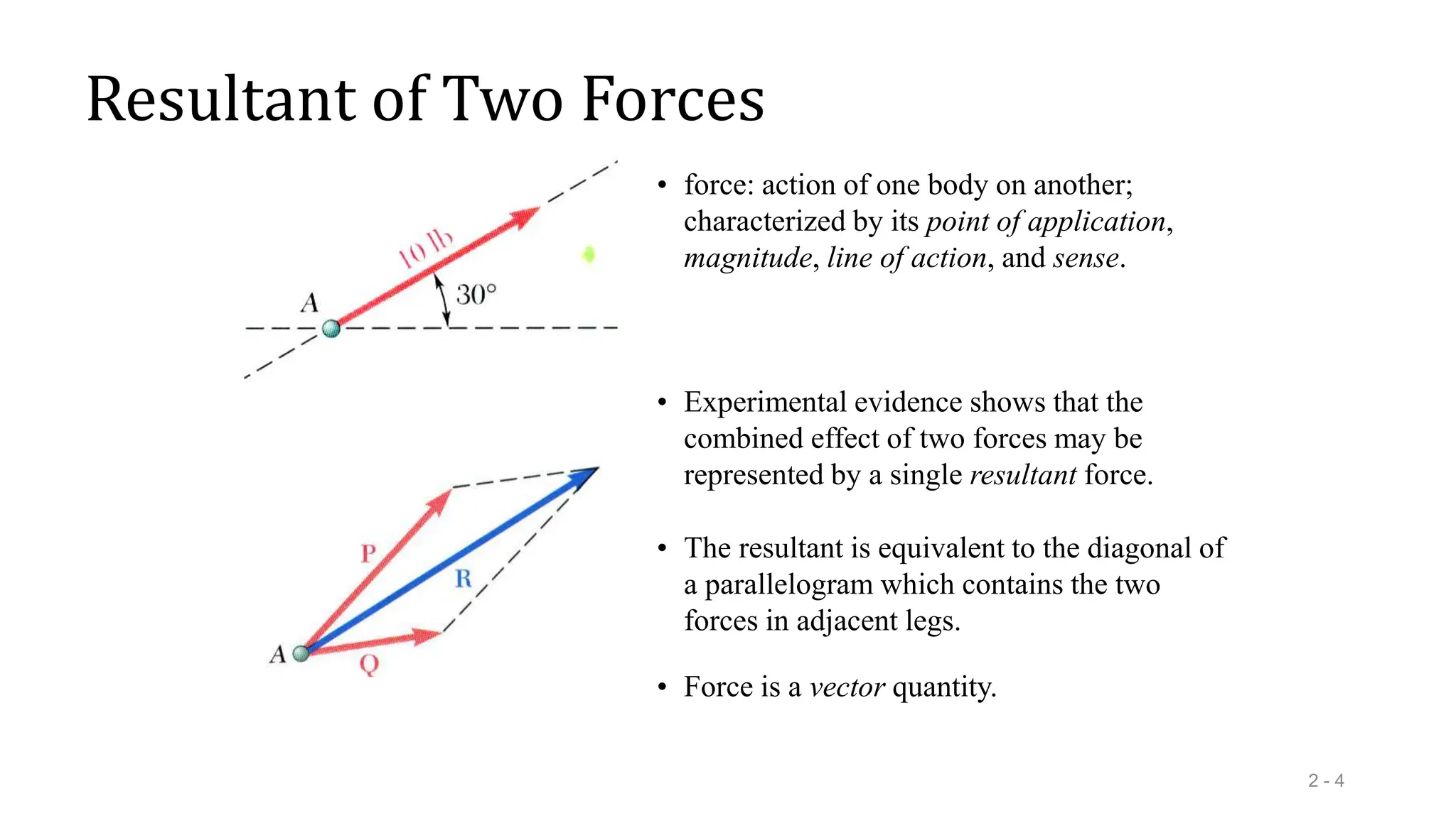
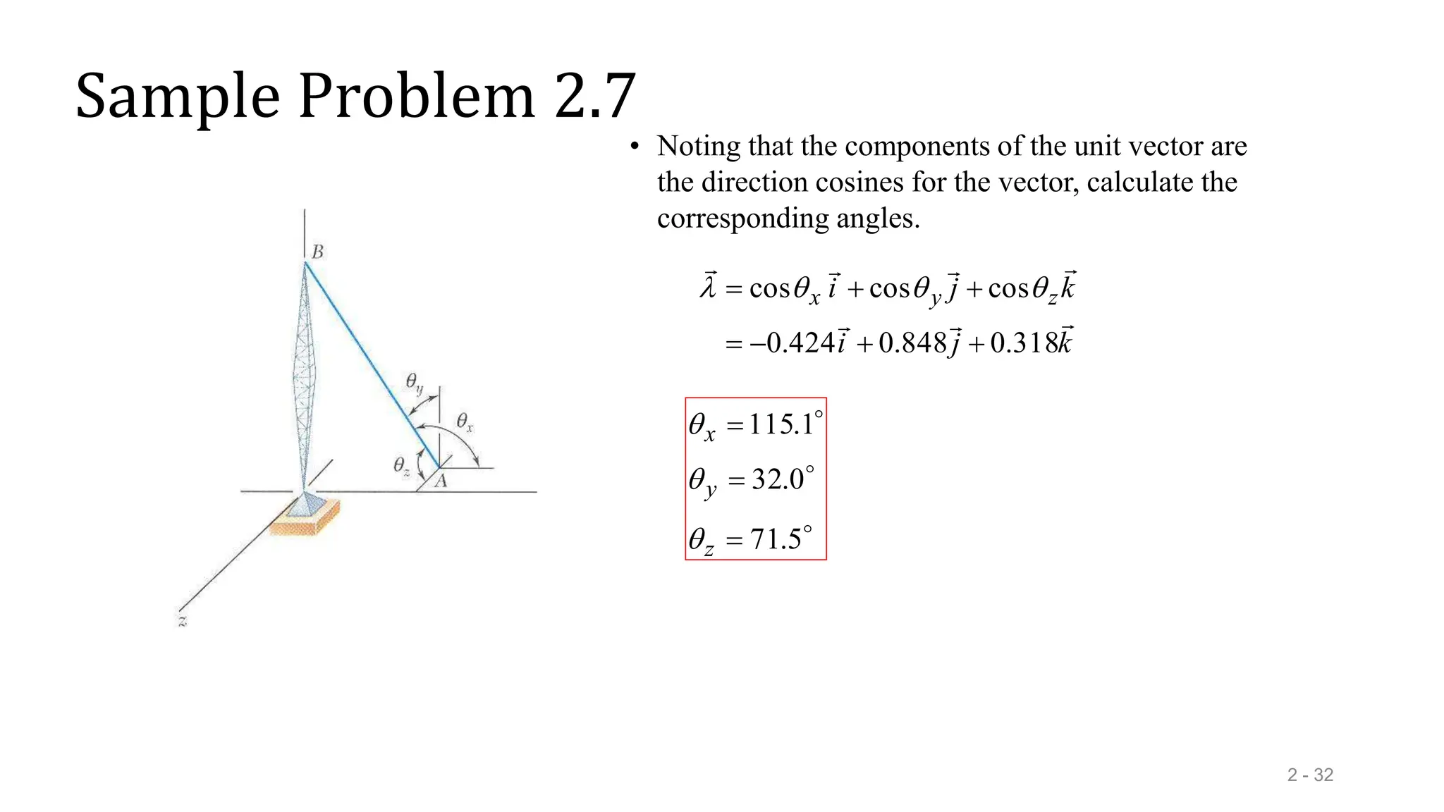
Statics of Particles
(Vector theory)
Lecture-02
CL-101 ENGINEERING MECHANICS
B. Tech Semester-I
Prof. Samirsinh P Parmar
Mail: samirddu@gmail.com
Asst. Professor, Department of Civil Engineering,
Faculty of Technology,
Dharmsinh Desai University, Nadiad-387001
Gujarat, INDIA
Contents
2 - 2
Introduction
Resultant of Two Forces
Vectors
Addition of Vectors
Resultant of Several Concurrent
Forces
Sample Problem 2.1
Sample Problem 2.2
Rectangular Components of a Force:
Unit Vectors
Addition of Forces by Summing
Components
Sample Problem 2.3
Equilibrium of a Particle
Free-Body Diagrams
Sample Problem 2.4
Sample Problem 2.6
Rectangular Components in Space
Sample Problem 2.7
Introduction
2 - 3
• The objective for the current chapter is to investigate the effects of forces
on particles:
- replacing multiple forces acting on a particle with a single
equivalent or resultant force,
- relations between forces acting on a particle that is in a state of
equilibrium.
• The focus on particles does not imply a restriction to miniscule bodies.
Rather, the study is restricted to analyses in which the size and shape of
the bodies is not significant so that all forces may be assumed to be
applied at a single point.
Resultant of Two Forces
2 - 4
• force: action of one body on another;
characterized by its point of application,
magnitude, line of action, and sense.
• Experimental evidence shows that the
combined effect of two forces may be
represented by a single resultant force.
• The resultant is equivalent to the diagonal of
a parallelogram which contains the two
forces in adjacent legs.
• Force is a vector quantity.
Vectors
2 - 5
• Vector: parameters possessing magnitude and direction
which add according to the parallelogram law. Examples:
displacements, velocities, accelerations.
• Vector classifications:
- Fixed or bound vectors have well defined points of
application that cannot be changed without affecting
an analysis.
- Free vectors may be freely moved in space without
changing their effect on an analysis.
- Sliding vectors may be applied anywhere along their
line of action without affecting an analysis.
• Equal vectors have the same magnitude and direction.
• Negative vector of a given vector has the same magnitude
and the opposite direction.
• Scalar: parameters possessing magnitude but not
direction. Examples: mass, volume, temperature
Addition of Vectors
2 - 6
• Trapezoid rule for vector addition
• Triangle rule for vector addition
B
B
C
C
Q
P
R
B
PQ
Q
P
R







 cos
2
2
2
2
• Law of cosines,
• Law of sines,
A
C
R
B
Q
A sin
sin
sin


• Vector addition is commutative,
P
Q
Q
P







• Vector subtraction
Addition of Vectors
2 - 7
• Addition of three or more vectors through
repeated application of the triangle rule
• The polygon rule for the addition of three or
more vectors.
• Vector addition is associative,
   
S
Q
P
S
Q
P
S
Q
P

















• Multiplication of a vector by a scalar
Resultant of Several Concurrent Forces
2 - 8
• Concurrent forces: set of forces which all
pass through the same point.
A set of concurrent forces applied to a
particle may be replaced by a single
resultant force which is the vector sum of the
applied forces.
• Vector force components: two or more force
vectors which, together, have the same effect
as a single force vector.
Sample Problem 2.1
2 - 9
The two forces act on a bolt at A.
Determine their resultant.
SOLUTION:
• Graphical solution - construct a
parallelogram with sides in the same
direction as P and Q and lengths in
proportion. Graphically evaluate the
resultant which is equivalent in direction
and proportional in magnitude to the the
diagonal.
• Trigonometric solution - use the triangle
rule for vector addition in conjunction
with the law of cosines and law of sines
to find the resultant.
Sample Problem 2.1
2 - 10
• Graphical solution - A parallelogram with sides
equal to P and Q is drawn to scale. The
magnitude and direction of the resultant or of
the diagonal to the parallelogram are measured,


 35
N
98 
R
• Graphical solution - A triangle is drawn with P
and Q head-to-tail and to scale. The magnitude
and direction of the resultant or of the third side
of the triangle are measured,


 35
N
98 
R
Sample Problem 2.1
2 - 11
• Trigonometric solution - Apply the triangle rule.
From the Law of Cosines,
       






155
cos
N
60
N
40
2
N
60
N
40
cos
2
2
2
2
2
2
B
PQ
Q
P
R
A
A
R
Q
B
A
R
B
Q
A









20
04
.
15
N
73
.
97
N
60
155
sin
sin
sin
sin
sin

N
73
.
97

R
From the Law of Sines,

 04
.
35

Sample Problem 2.2
2 - 12
a) the tension in each of the ropes
for  = 45o,
b) the value of  for which the
tension in rope 2 is a minimum.
A barge is pulled by two tugboats.
If the resultant of the forces
exerted by the tugboats is 5000 lbf
directed along the axis of the
barge, determine
SOLUTION:
• Find a graphical solution by applying the
Parallelogram Rule for vector addition. The
parallelogram has sides in the directions of
the two ropes and a diagonal in the direction
of the barge axis and length proportional to
5000 lbf.
• The angle for minimum tension in rope 2 is
determined by applying the Triangle Rule
and observing the effect of variations in .
• Find a trigonometric solution by applying
the Triangle Rule for vector addition. With
the magnitude and direction of the resultant
known and the directions of the other two
sides parallel to the ropes given, apply the
Law of Sines to find the rope tensions.
Sample Problem 2.2
2 - 13
• Graphical solution - Parallelogram Rule
with known resultant direction and
magnitude, known directions for sides.
lbf
2600
lbf
3700 2
1 
 T
T
• Trigonometric solution - Triangle Rule
with Law of Sines




 105
sin
lbf
5000
30
sin
45
sin
2
1 T
T
lbf
2590
lbf
3660 2
1 
 T
T
Sample Problem 2.2
2 - 14
• The angle for minimum tension in rope 2 is
determined by applying the Triangle Rule
and observing the effect of variations in .
• The minimum tension in rope 2 occurs when
T1 and T2 are perpendicular.
  
 30
sin
lbf
5000
2
T lbf
2500
2 
T
  
 30
cos
lbf
5000
1
T lbf
4330
1 
T



 30
90
 
 60

Rectangular Components of a Force: Unit Vectors
2 - 15
• Vector components may be expressed as products of
the unit vectors with the scalar magnitudes of the
vector components.
Fx and Fy are referred to as the scalar components of
j
F
i
F
F y
x





F

• May resolve a force vector into perpendicular
components so that the resulting parallelogram is a
rectangle. are referred to as rectangular
vector components and
y
x F
F
F





y
x F
F


and
• Define perpendicular unit vectors which are
parallel to the x and y axes.
j
i


and
Addition of Forces by Summing Components
2 - 16
S
Q
P
R







• Wish to find the resultant of 3 or more
concurrent forces,
   j
S
Q
P
i
S
Q
P
j
S
i
S
j
Q
i
Q
j
P
i
P
j
R
i
R
y
y
y
x
x
x
y
x
y
x
y
x
y
x























• Resolve each force into rectangular components





x
x
x
x
x
F
S
Q
P
R
• The scalar components of the resultant are equal
to the sum of the corresponding scalar
components of the given forces.





y
y
y
y
y
F
S
Q
P
R
x
y
y
x
R
R
R
R
R 1
2
2
tan


 
• To find the resultant magnitude and direction,
Sample Problem 2.3
2 - 17
Four forces act on bolt A as shown.
Determine the resultant of the force
on the bolt.
SOLUTION:
• Resolve each force into rectangular
components.
• Calculate the magnitude and direction
of the resultant.
• Determine the components of the
resultant by adding the corresponding
force components.
Sample Problem 2.3
2 - 18
SOLUTION:
• Resolve each force into rectangular components.
9
.
25
6
.
96
100
0
.
110
0
110
2
.
75
4
.
27
80
0
.
75
9
.
129
150
4
3
2
1









F
F
F
F
comp
y
comp
x
mag
force




2
2
3
.
14
1
.
199 

R N
6
.
199

R
• Calculate the magnitude and direction.
N
1
.
199
N
3
.
14
tan 
 
 1
.
4

• Determine the components of the resultant by
adding the corresponding force components.
1
.
199


x
R 3
.
14


y
R
Equilibrium of a Particle
2 - 19
• When the resultant of all forces acting on a particle is zero, the particle is
in equilibrium.
• Particle acted upon by
two forces:
- equal magnitude
- same line of action
- opposite sense
• Particle acted upon by three or more forces:
- graphical solution yields a closed polygon
- algebraic solution
0
0
0







y
x F
F
F
R


• Newton’s First Law: If the resultant force on a particle is zero, the particle will
remain at rest or will continue at constant speed in a straight line.
Free-Body Diagrams
2 - 20
Space Diagram: A sketch showing
the physical conditions of the
problem.
Free-Body Diagram: A sketch showing
only the forces on the selected particle.
Sample Problem 2.4
2 - 21
In a ship-unloading operation, a
3500-lb automobile is supported by
a cable. A rope is tied to the cable
and pulled to center the automobile
over its intended position. What is
the tension in the rope?
SOLUTION:
• Construct a free-body diagram for the
particle at the junction of the rope and
cable.
• Apply the conditions for equilibrium by
creating a closed polygon from the
forces applied to the particle.
• Apply trigonometric relations to
determine the unknown force
magnitudes.
Sample Problem 2.4
2 - 22
SOLUTION:
• Construct a free-body diagram for the
particle at A.
• Apply the conditions for equilibrium.
• Solve for the unknown force magnitudes.




 58
sin
lb
3500
2
sin
120
sin
AC
AB T
T
lb
3570

AB
T
lb
144

AC
T
Sample Problem 2.6
2 - 23
It is desired to determine the drag force
at a given speed on a prototype sailboat
hull. A model is placed in a test channel
and three cables are used to align its
bow on the channel centerline. For a
given speed, the tension is 40 lb in
cable AB and 60 lb in cable AE.
Determine the drag force exerted on the
hull and the tension in cable AC.
SOLUTION:
• Choosing the hull as the free body,
draw a free-body diagram.
• Express the condition for equilibrium
for the hull by writing that the sum of
all forces must be zero.
• Resolve the vector equilibrium
equation into two component
equations. Solve for the two unknown
cable tensions.
Sample Problem 2.6
2 - 24
SOLUTION:
• Choosing the hull as the free body, draw a
free-body diagram.




25
.
60
75
.
1
ft
4
ft
7
tan






56
.
20
375
.
0
ft
4
ft
1.5
tan


• Express the condition for equilibrium
for the hull by writing that the sum of
all forces must be zero.
0




 D
AE
AC
AB F
T
T
T
R





Sample Problem 2.6
2 - 25
• Resolve the vector equilibrium equation into
two component equations. Solve for the two
unknown cable tensions.
   
   
 
 
  j
T
i
F
T
R
i
F
F
i
T
j
T
i
T
j
T
i
T
T
j
i
j
i
T
AC
D
AC
D
D
AC
AC
AC
AC
AC
AB

















60
9363
.
0
84
.
19
3512
.
0
73
.
34
0
lb
0
6
9363
.
0
3512
.
0
56
.
20
cos
56
.
20
sin
lb
84
.
19
lb
73
.
34
26
.
60
cos
lb
40
26
.
60
sin
lb
40

























Sample Problem 2.6
2 - 26
 
  j
T
i
F
T
R
AC
D
AC



60
9363
.
0
84
.
19
3512
.
0
73
.
34
0








This equation is satisfied only if each component
of the resultant is equal to zero
 
  60
9363
.
0
84
.
19
0
0
3512
.
0
73
.
34
0
0











AC
y
D
AC
x
T
F
F
T
F
lb
66
.
19
lb
9
.
42




D
AC
F
T
Rectangular Components in Space
2 - 27
• The vector is
contained in the
plane OBAC.
F

• Resolve into
horizontal and vertical
components.
y
h F
F 
sin

F

y
y F
F 
cos

• Resolve into
rectangular components
h
F






sin
sin
sin
cos
sin
cos
y
h
y
y
h
x
F
F
F
F
F
F




Rectangular Components in Space
2 - 28
• With the angles between and the axes,
F

 
k
j
i
F
k
j
i
F
k
F
j
F
i
F
F
F
F
F
F
F
F
z
y
x
z
y
x
z
y
x
z
z
y
y
x
x























cos
cos
cos
cos
cos
cos
cos
cos
cos













• is a unit vector along the line of action of
and are the direction
cosines for
F

F



z
y
x 

 cos
and
,
cos
,
cos
Rectangular Components in Space
2 - 29
Direction of the force is defined by
the location of two points,
   
2
2
2
1
1
1 ,
,
and
,
, z
y
x
N
z
y
x
M
 
d
Fd
F
d
Fd
F
d
Fd
F
k
d
j
d
i
d
d
F
F
z
z
d
y
y
d
x
x
d
k
d
j
d
i
d
N
M
d
z
z
y
y
x
x
z
y
x
z
y
x
z
y
x



























1
and
joining
vector
1
2
1
2
1
2


Sample Problem 2.7
2 - 30
The tension in the guy wire is 2500 N.
Determine:
a) components Fx, Fy, Fz of the force
acting on the bolt at A,
b) the angles x, y, z defining the
direction of the force
SOLUTION:
• Based on the relative locations of the
points A and B, determine the unit
vector pointing from A towards B.
• Apply the unit vector to determine the
components of the force acting on A.
• Noting that the components of the unit
vector are the direction cosines for the
vector, calculate the corresponding
angles.
Sample Problem 2.7
2 - 31
SOLUTION:
• Determine the unit vector pointing from A
towards B.
     
     
m
3
.
94
m
30
m
80
m
40
m
30
m
80
m
40
2
2
2









AB
k
j
i
AB



• Determine the components of the force.
  
     k
j
i
k
j
i
F
F








N
795
N
2120
N
1060
318
.
0
848
.
0
424
.
0
N
2500








 
k
j
i
k
j
i







318
.
0
848
.
0
424
.
0
3
.
94
30
3
.
94
80
3
.
94
40























 


Sample Problem 2.7
2 - 32
• Noting that the components of the unit vector are
the direction cosines for the vector, calculate the
corresponding angles.
k
j
i
k
j
i z
y
x







318
.
0
848
.
0
424
.
0
cos
cos
cos






 






5
.
71
0
.
32
1
.
115



z
y
x



2 - 33

Ch-02 Statics of Particles.ppt

  • 1.
    Statics of Particles (Vectortheory) Lecture-02 CL-101 ENGINEERING MECHANICS B. Tech Semester-I Prof. Samirsinh P Parmar Mail: samirddu@gmail.com Asst. Professor, Department of Civil Engineering, Faculty of Technology, Dharmsinh Desai University, Nadiad-387001 Gujarat, INDIA
  • 2.
    Contents 2 - 2 Introduction Resultantof Two Forces Vectors Addition of Vectors Resultant of Several Concurrent Forces Sample Problem 2.1 Sample Problem 2.2 Rectangular Components of a Force: Unit Vectors Addition of Forces by Summing Components Sample Problem 2.3 Equilibrium of a Particle Free-Body Diagrams Sample Problem 2.4 Sample Problem 2.6 Rectangular Components in Space Sample Problem 2.7
  • 3.
    Introduction 2 - 3 •The objective for the current chapter is to investigate the effects of forces on particles: - replacing multiple forces acting on a particle with a single equivalent or resultant force, - relations between forces acting on a particle that is in a state of equilibrium. • The focus on particles does not imply a restriction to miniscule bodies. Rather, the study is restricted to analyses in which the size and shape of the bodies is not significant so that all forces may be assumed to be applied at a single point.
  • 4.
    Resultant of TwoForces 2 - 4 • force: action of one body on another; characterized by its point of application, magnitude, line of action, and sense. • Experimental evidence shows that the combined effect of two forces may be represented by a single resultant force. • The resultant is equivalent to the diagonal of a parallelogram which contains the two forces in adjacent legs. • Force is a vector quantity.
  • 5.
    Vectors 2 - 5 •Vector: parameters possessing magnitude and direction which add according to the parallelogram law. Examples: displacements, velocities, accelerations. • Vector classifications: - Fixed or bound vectors have well defined points of application that cannot be changed without affecting an analysis. - Free vectors may be freely moved in space without changing their effect on an analysis. - Sliding vectors may be applied anywhere along their line of action without affecting an analysis. • Equal vectors have the same magnitude and direction. • Negative vector of a given vector has the same magnitude and the opposite direction. • Scalar: parameters possessing magnitude but not direction. Examples: mass, volume, temperature
  • 6.
    Addition of Vectors 2- 6 • Trapezoid rule for vector addition • Triangle rule for vector addition B B C C Q P R B PQ Q P R         cos 2 2 2 2 • Law of cosines, • Law of sines, A C R B Q A sin sin sin   • Vector addition is commutative, P Q Q P        • Vector subtraction
  • 7.
    Addition of Vectors 2- 7 • Addition of three or more vectors through repeated application of the triangle rule • The polygon rule for the addition of three or more vectors. • Vector addition is associative,     S Q P S Q P S Q P                  • Multiplication of a vector by a scalar
  • 8.
    Resultant of SeveralConcurrent Forces 2 - 8 • Concurrent forces: set of forces which all pass through the same point. A set of concurrent forces applied to a particle may be replaced by a single resultant force which is the vector sum of the applied forces. • Vector force components: two or more force vectors which, together, have the same effect as a single force vector.
  • 9.
    Sample Problem 2.1 2- 9 The two forces act on a bolt at A. Determine their resultant. SOLUTION: • Graphical solution - construct a parallelogram with sides in the same direction as P and Q and lengths in proportion. Graphically evaluate the resultant which is equivalent in direction and proportional in magnitude to the the diagonal. • Trigonometric solution - use the triangle rule for vector addition in conjunction with the law of cosines and law of sines to find the resultant.
  • 10.
    Sample Problem 2.1 2- 10 • Graphical solution - A parallelogram with sides equal to P and Q is drawn to scale. The magnitude and direction of the resultant or of the diagonal to the parallelogram are measured,    35 N 98  R • Graphical solution - A triangle is drawn with P and Q head-to-tail and to scale. The magnitude and direction of the resultant or of the third side of the triangle are measured,    35 N 98  R
  • 11.
    Sample Problem 2.1 2- 11 • Trigonometric solution - Apply the triangle rule. From the Law of Cosines,               155 cos N 60 N 40 2 N 60 N 40 cos 2 2 2 2 2 2 B PQ Q P R A A R Q B A R B Q A          20 04 . 15 N 73 . 97 N 60 155 sin sin sin sin sin  N 73 . 97  R From the Law of Sines,   04 . 35 
  • 12.
    Sample Problem 2.2 2- 12 a) the tension in each of the ropes for  = 45o, b) the value of  for which the tension in rope 2 is a minimum. A barge is pulled by two tugboats. If the resultant of the forces exerted by the tugboats is 5000 lbf directed along the axis of the barge, determine SOLUTION: • Find a graphical solution by applying the Parallelogram Rule for vector addition. The parallelogram has sides in the directions of the two ropes and a diagonal in the direction of the barge axis and length proportional to 5000 lbf. • The angle for minimum tension in rope 2 is determined by applying the Triangle Rule and observing the effect of variations in . • Find a trigonometric solution by applying the Triangle Rule for vector addition. With the magnitude and direction of the resultant known and the directions of the other two sides parallel to the ropes given, apply the Law of Sines to find the rope tensions.
  • 13.
    Sample Problem 2.2 2- 13 • Graphical solution - Parallelogram Rule with known resultant direction and magnitude, known directions for sides. lbf 2600 lbf 3700 2 1   T T • Trigonometric solution - Triangle Rule with Law of Sines      105 sin lbf 5000 30 sin 45 sin 2 1 T T lbf 2590 lbf 3660 2 1   T T
  • 14.
    Sample Problem 2.2 2- 14 • The angle for minimum tension in rope 2 is determined by applying the Triangle Rule and observing the effect of variations in . • The minimum tension in rope 2 occurs when T1 and T2 are perpendicular.     30 sin lbf 5000 2 T lbf 2500 2  T     30 cos lbf 5000 1 T lbf 4330 1  T     30 90    60 
  • 15.
    Rectangular Components ofa Force: Unit Vectors 2 - 15 • Vector components may be expressed as products of the unit vectors with the scalar magnitudes of the vector components. Fx and Fy are referred to as the scalar components of j F i F F y x      F  • May resolve a force vector into perpendicular components so that the resulting parallelogram is a rectangle. are referred to as rectangular vector components and y x F F F      y x F F   and • Define perpendicular unit vectors which are parallel to the x and y axes. j i   and
  • 16.
    Addition of Forcesby Summing Components 2 - 16 S Q P R        • Wish to find the resultant of 3 or more concurrent forces,    j S Q P i S Q P j S i S j Q i Q j P i P j R i R y y y x x x y x y x y x y x                        • Resolve each force into rectangular components      x x x x x F S Q P R • The scalar components of the resultant are equal to the sum of the corresponding scalar components of the given forces.      y y y y y F S Q P R x y y x R R R R R 1 2 2 tan     • To find the resultant magnitude and direction,
  • 17.
    Sample Problem 2.3 2- 17 Four forces act on bolt A as shown. Determine the resultant of the force on the bolt. SOLUTION: • Resolve each force into rectangular components. • Calculate the magnitude and direction of the resultant. • Determine the components of the resultant by adding the corresponding force components.
  • 18.
    Sample Problem 2.3 2- 18 SOLUTION: • Resolve each force into rectangular components. 9 . 25 6 . 96 100 0 . 110 0 110 2 . 75 4 . 27 80 0 . 75 9 . 129 150 4 3 2 1          F F F F comp y comp x mag force     2 2 3 . 14 1 . 199   R N 6 . 199  R • Calculate the magnitude and direction. N 1 . 199 N 3 . 14 tan     1 . 4  • Determine the components of the resultant by adding the corresponding force components. 1 . 199   x R 3 . 14   y R
  • 19.
    Equilibrium of aParticle 2 - 19 • When the resultant of all forces acting on a particle is zero, the particle is in equilibrium. • Particle acted upon by two forces: - equal magnitude - same line of action - opposite sense • Particle acted upon by three or more forces: - graphical solution yields a closed polygon - algebraic solution 0 0 0        y x F F F R   • Newton’s First Law: If the resultant force on a particle is zero, the particle will remain at rest or will continue at constant speed in a straight line.
  • 20.
    Free-Body Diagrams 2 -20 Space Diagram: A sketch showing the physical conditions of the problem. Free-Body Diagram: A sketch showing only the forces on the selected particle.
  • 21.
    Sample Problem 2.4 2- 21 In a ship-unloading operation, a 3500-lb automobile is supported by a cable. A rope is tied to the cable and pulled to center the automobile over its intended position. What is the tension in the rope? SOLUTION: • Construct a free-body diagram for the particle at the junction of the rope and cable. • Apply the conditions for equilibrium by creating a closed polygon from the forces applied to the particle. • Apply trigonometric relations to determine the unknown force magnitudes.
  • 22.
    Sample Problem 2.4 2- 22 SOLUTION: • Construct a free-body diagram for the particle at A. • Apply the conditions for equilibrium. • Solve for the unknown force magnitudes.      58 sin lb 3500 2 sin 120 sin AC AB T T lb 3570  AB T lb 144  AC T
  • 23.
    Sample Problem 2.6 2- 23 It is desired to determine the drag force at a given speed on a prototype sailboat hull. A model is placed in a test channel and three cables are used to align its bow on the channel centerline. For a given speed, the tension is 40 lb in cable AB and 60 lb in cable AE. Determine the drag force exerted on the hull and the tension in cable AC. SOLUTION: • Choosing the hull as the free body, draw a free-body diagram. • Express the condition for equilibrium for the hull by writing that the sum of all forces must be zero. • Resolve the vector equilibrium equation into two component equations. Solve for the two unknown cable tensions.
  • 24.
    Sample Problem 2.6 2- 24 SOLUTION: • Choosing the hull as the free body, draw a free-body diagram.     25 . 60 75 . 1 ft 4 ft 7 tan       56 . 20 375 . 0 ft 4 ft 1.5 tan   • Express the condition for equilibrium for the hull by writing that the sum of all forces must be zero. 0      D AE AC AB F T T T R     
  • 25.
    Sample Problem 2.6 2- 25 • Resolve the vector equilibrium equation into two component equations. Solve for the two unknown cable tensions.               j T i F T R i F F i T j T i T j T i T T j i j i T AC D AC D D AC AC AC AC AC AB                  60 9363 . 0 84 . 19 3512 . 0 73 . 34 0 lb 0 6 9363 . 0 3512 . 0 56 . 20 cos 56 . 20 sin lb 84 . 19 lb 73 . 34 26 . 60 cos lb 40 26 . 60 sin lb 40                         
  • 26.
    Sample Problem 2.6 2- 26     j T i F T R AC D AC    60 9363 . 0 84 . 19 3512 . 0 73 . 34 0         This equation is satisfied only if each component of the resultant is equal to zero     60 9363 . 0 84 . 19 0 0 3512 . 0 73 . 34 0 0            AC y D AC x T F F T F lb 66 . 19 lb 9 . 42     D AC F T
  • 27.
    Rectangular Components inSpace 2 - 27 • The vector is contained in the plane OBAC. F  • Resolve into horizontal and vertical components. y h F F  sin  F  y y F F  cos  • Resolve into rectangular components h F       sin sin sin cos sin cos y h y y h x F F F F F F    
  • 28.
    Rectangular Components inSpace 2 - 28 • With the angles between and the axes, F    k j i F k j i F k F j F i F F F F F F F F z y x z y x z y x z z y y x x                        cos cos cos cos cos cos cos cos cos              • is a unit vector along the line of action of and are the direction cosines for F  F    z y x    cos and , cos , cos
  • 29.
    Rectangular Components inSpace 2 - 29 Direction of the force is defined by the location of two points,     2 2 2 1 1 1 , , and , , z y x N z y x M   d Fd F d Fd F d Fd F k d j d i d d F F z z d y y d x x d k d j d i d N M d z z y y x x z y x z y x z y x                            1 and joining vector 1 2 1 2 1 2  
  • 30.
    Sample Problem 2.7 2- 30 The tension in the guy wire is 2500 N. Determine: a) components Fx, Fy, Fz of the force acting on the bolt at A, b) the angles x, y, z defining the direction of the force SOLUTION: • Based on the relative locations of the points A and B, determine the unit vector pointing from A towards B. • Apply the unit vector to determine the components of the force acting on A. • Noting that the components of the unit vector are the direction cosines for the vector, calculate the corresponding angles.
  • 31.
    Sample Problem 2.7 2- 31 SOLUTION: • Determine the unit vector pointing from A towards B.             m 3 . 94 m 30 m 80 m 40 m 30 m 80 m 40 2 2 2          AB k j i AB    • Determine the components of the force.         k j i k j i F F         N 795 N 2120 N 1060 318 . 0 848 . 0 424 . 0 N 2500           k j i k j i        318 . 0 848 . 0 424 . 0 3 . 94 30 3 . 94 80 3 . 94 40                           
  • 32.
    Sample Problem 2.7 2- 32 • Noting that the components of the unit vector are the direction cosines for the vector, calculate the corresponding angles. k j i k j i z y x        318 . 0 848 . 0 424 . 0 cos cos cos               5 . 71 0 . 32 1 . 115    z y x   
  • 33.