The document discusses basic principles of statics and structural design. It covers:
1) Statics deals with forces on bodies at rest, while dynamics deals with moving bodies. Statics is used to analyze structural systems and ensure strength, stiffness, and stability.
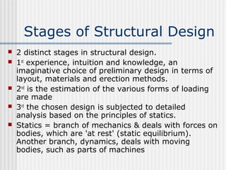
2) Structural design involves preliminary design stages using experience and intuition, followed by detailed analysis and load estimations based on statics principles.
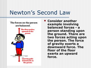
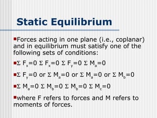
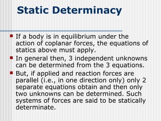
3) Static equilibrium equations must be satisfied for coplanar forces. Systems can be determinate, allowing determination of specific unknowns, or indeterminate.


![Ctm 154[1]](https://cdn.slidesharecdn.com/ss_thumbnails/ctm1541-190506153756-thumbnail.jpg?width=640&height=640&fit=bounds)