This document is a manual for the CFC (Continuous Function Chart) configuration tool used with Siemens' Simatic S7 programmable controllers. It provides essential information on using the tool, including setup, testing, and safety guidelines, while also emphasizing that only qualified personnel should operate the device/system as per the documented instructions. The manual covers various aspects of CFC, including creating and managing projects, using the editor, testing and commissioning processes, and technical support resources.


![Contents
CFC for S7
A5E00345244-01 ix
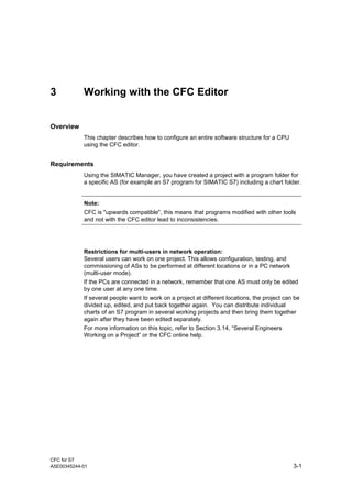
5 Documentation 5-1
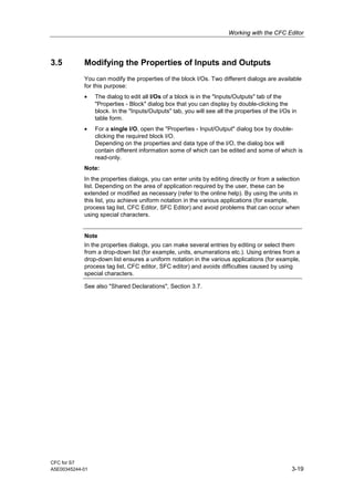
5.1 Printing a CFC...................................................................................................5-1
5.1.1 Footer................................................................................................................5-2
5.2 Chart Reference Data .......................................................................................5-3
5.2.1 Lists of the Chart Reference Data.....................................................................5-4
5.3 Logs...................................................................................................................5-4
A Technical Specifications A-1
A.1 [S7] Technical Specifications ........................................................................... A-1
A.2 Field/Name Lengths and Conventions............................................................. A-2
A.3 [S7] Data types................................................................................................. A-3
B Abbreviations B-1
Index](https://image.slidesharecdn.com/cfcfors7e-160816135057/85/Cfc-for-s7_e-9-320.jpg)


![Working with the CFC Editor
CFC for S7
A5E00345244-01 3-43
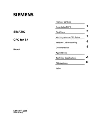
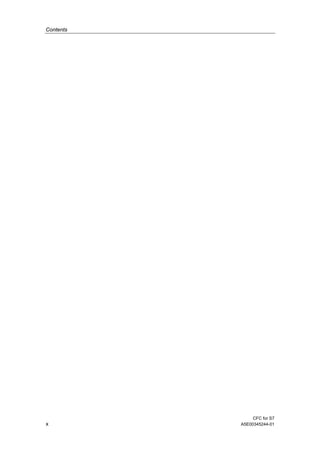
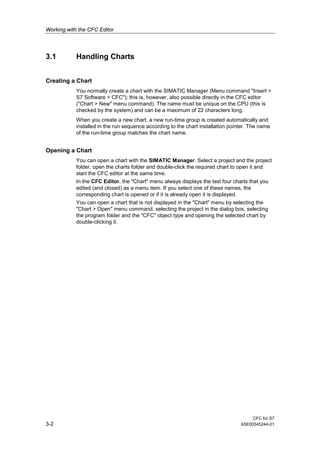
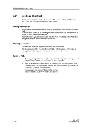
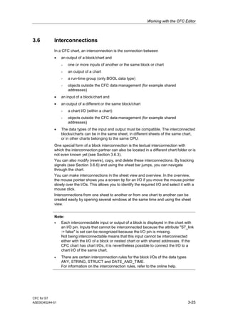
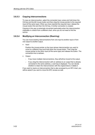
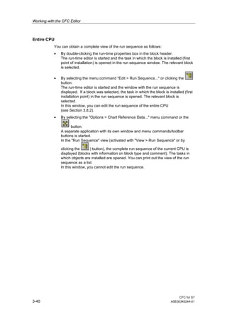
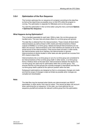
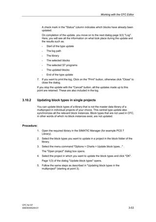
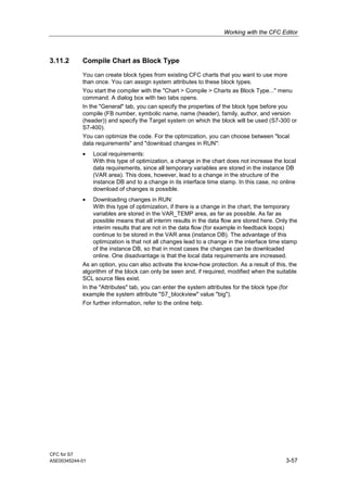
3.8.2 Modifying the Run Sequence and the Installation Pointer
Starting the Run-Time Editor
With the menu command "Edit > Run Sequence..." or by clicking the icon in
the toolbar, you open a divided window with the hierarchy window on the left and a
detailed window on the right. This is structured similar to the Windows Explorer and
working with it is similar.
Moving Objects
You can move an object (chart, run-time group or block) by selecting it (in the right
or left window) and dragging it to the object after which you want to install it (drag-
and-drop).
If you drag an object to a run-time group,
• the object is installed at the first position within the run-time group when the
structure is expanded [-].
• the object is installed after the run-time group if the structure is not expanded
[+].
• and the run-time group is empty, you will be asked whether or not you want to
install the block within the run-time group. If you acknowledge with "yes" the
object will be installed inside, if you answer "no", it will be installed after the
run-time group.
If you drag an object to a block/chart within the run-time group, the object will be
installed after this block/chart.
If you drag an object to a task, it is installed before the existing installed objects.
Note
When moving blocks, make sure that all blocks of a chart are located only in the
relevant run-time group. After moving a block to another group, the chart-oriented
structure would longer exist and would make it difficult or even impossible to work
on a chart-by-chart basis in multiuser engineering.
Removing a Block
You can only remove blocks (delete) from a task if they are installed more than
once in the run sequence. The block must remain installed at least once.
If the block is installed only once, you cannot delete it. If it exists more than once,
the block is deleted and the run sequence of the blocks following this position is
updated.](https://image.slidesharecdn.com/cfcfors7e-160816135057/85/Cfc-for-s7_e-83-320.jpg)


![CFC for S7
A5E00345244-01 A-1
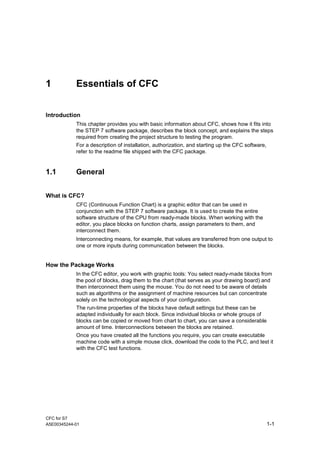
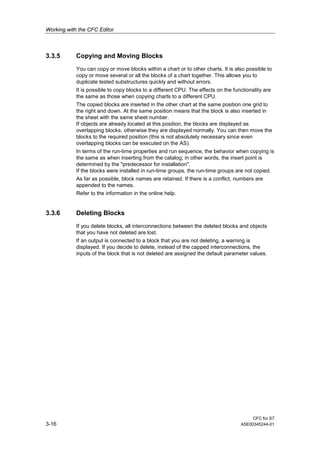
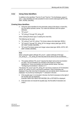
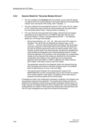
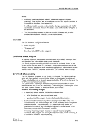
A Technical Specifications
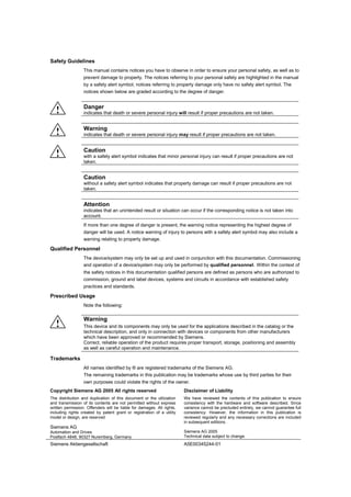
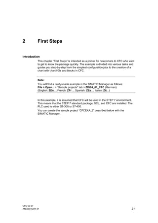
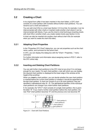
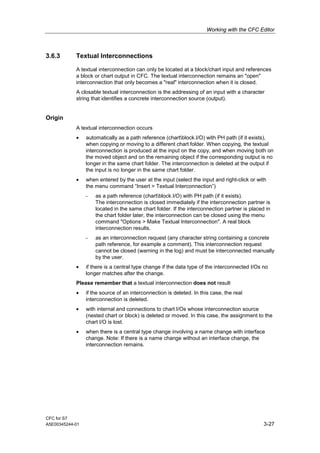
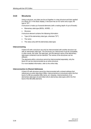
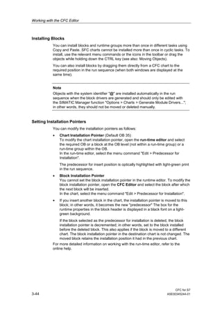
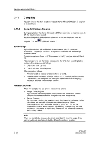
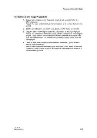
A.1 [S7] Technical Specifications
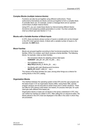
Hardware Requirements
• SIMATIC PG or PC
• Pentium processor 1 GHz (or higher)
• RAM at least 512 Mbytes (or more)
• Graphics card SVGA 1024 x 768 (or higher)
• MPI connection for online operation
• SIMATIC S7-300, S7-400
Software Requirements
• Microsoft Windows 2000 (SP3)
or
• Microsoft Windows XP (SP1)
• STEP 7 V5.3 SP1 or higher
• S7-SCL V5.1 SP3 or higher](https://image.slidesharecdn.com/cfcfors7e-160816135057/85/Cfc-for-s7_e-123-320.jpg)
![Technical Specifications
CFC for S7
A5E00177297-01 A-3
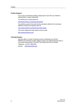
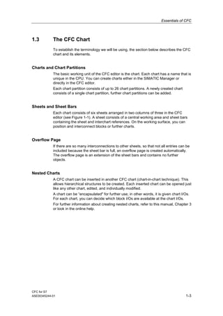
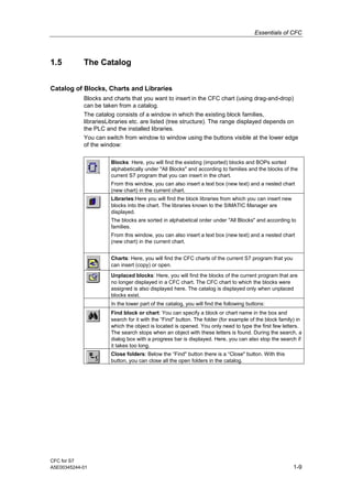
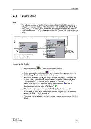
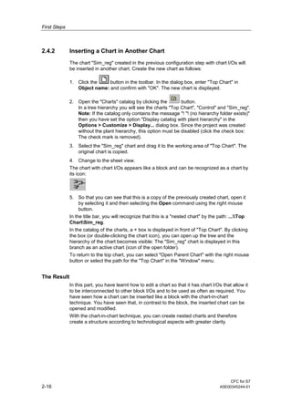
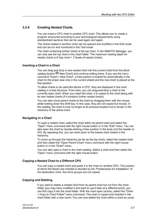
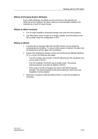
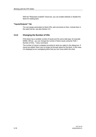
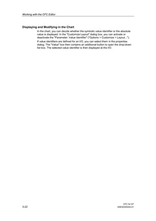
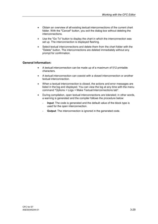
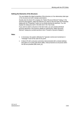
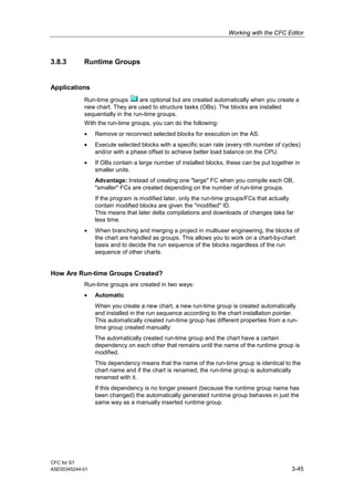
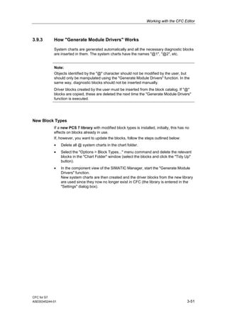
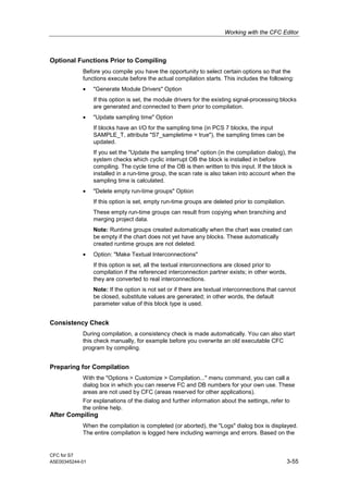
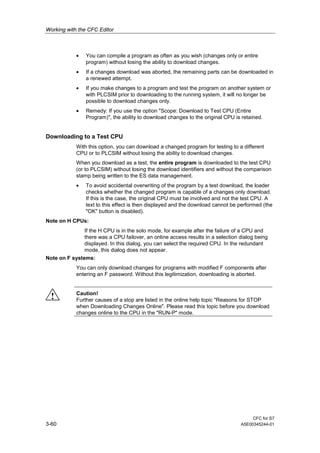
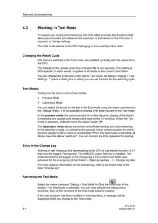
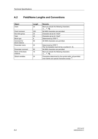
A.3 [S7] Data types
Abb. Keyword Meaning Bits
A ANY Pointer to data element 80
BO BOOL Logical number 1
BY BYTE Sequence of 8 bits 8
C CHAR Single character 8
CR COUNTER Number of an S7 counter 16
D DATE Date 16
DB BLOCK_DB Number of a DB 16
DI DINT Double integer 32
DT DATE_AND_TIME or DT Date and time 64
DW DWORD Sequence of 32 bits 32
FB BLOCK_FB Number of an FB 16
FC BLOCK_FC Number of an FC 16
I INT Integer 16
P POINTER Pointer to memory area 48
R REAL Floating-point number 32
S STRING Text string of any length 256 bytes
SD BLOCK_SDB Number of an SDB 16
SN STRING[n] Text string with maximum n characters, 1 < n < 253
ST STRUCT Parenthesis for elementary data types and other
structures (nesting depth: 8)
T TIME_OF_DAY or TOD Timer 32
TI TIME Duration 32
TR TIMER Number of an S7 timer 16
T5 S5TIME Duration in S5 format 16
W WORD Sequence of 16 bits 16
For a detailed description of the data types, refer to the online help.](https://image.slidesharecdn.com/cfcfors7e-160816135057/85/Cfc-for-s7_e-125-320.jpg)


![E20001 a239-p280-x-7600[1]](https://cdn.slidesharecdn.com/ss_thumbnails/e20001-a239-p280-x-76001-140908052339-phpapp01-thumbnail.jpg?width=640&height=640&fit=bounds)