This document provides an overview and technical specifications for various Siemens S7-300 automation system modules, including:
1. General technical data that applies to all modules such as standards, approvals, environmental conditions, and specifications.
2. Details on power supply modules including ratings for 3 different power modules ranging from 2A to 10A.
3. Information on digital input/output modules including module overview, selection guidance, programming, diagnostics, and specifications for 16 different digital I/O modules covering a range of channel counts and voltage types.


![Technical specifications
230 V AC
1.0 A
0.5 A
2.0 A
1.0 A
0.5 A
0.7 million 2)
1.5 million 2)
0.5 million 2)
0.7 million 2)
1.5 million
• with inductive load to IEC 947-5-1 DC13/AC15
Voltage Current No. of switching cycles (typ
ical)
24 V DC
60 V DC
120 V DC
48 V AC
60 V AC
120 V AC
230 V AC
2.0 A
1.0 A
0.5 A
0.5 A
0.2 A
1.5 A
1.5 A
2.0 A
1.0 A
0.7 A
0.5 A
2.0 A
1.0 A
0.5 A
0.3 million
0.5 million
1.0 million
0.5 million
0.3 million 2)
1 million
1 million
0.2 million
0.7 million
1 million
2.0 million
0.3 million 2)
0.7 million 2)
2 million 2)
Contact protection (internal) Varistor SIOV-CU4032 K275 G
An external protective circuit extends the useful life of contacts.
Actuator selection data [continued]
Lamp load 1) max. 50 W
Power No. of switching cycles (typ
ical)
Lamp load (230 V AC) 2) 700 W
1500 W
25000
10000
Energy-saving lamps/fluorescent lamps with electronic ballast2) 10 x 58 W 25000
Fluorescent lamps, conventionally compensated 2) 1 x 58 W 25000
Fluorescent lamps, non-compensated 2) 10 x 58 W 25000
Wiring two outputs in parallel
• for redundant load control supported (only outputs of the same group)
• for performance increase not supported
Control of a digital input supported
Switching frequency
• Mechanical max. 10 Hz
• with resistive load max. 2 Hz
• with inductive load to IEC 947-5-1, DC13/AC15 max. 0.5 Hz
• with lamp load max. 2 Hz
Wiring of the actuators using a 20-pin front connector
1) Product version 1
2) Product version 2 or higher
175
Digital modules
3.34 Relay output module SM 322; DO 8 x Rel. AC 230 V; (6ES7322-1HF01-0AA0)
S7-300 Module data
Equipment Manual, 05/2022, A5E00105505-AK](https://image.slidesharecdn.com/s7300moduledatamanualen-usen-us-240219101031-97f0fc5a/75/s7300_module_data_manual_en-US_en-US-pdf-175-2048.jpg)


![Measuring range module settings
Measuring range Measuring range module setting
Thermocouple TC-I
(internal comparison) (thermal
voltage measurement)
Linearization is ignored
Thermocouple TC-E
(external comparison) (thermo
voltage measurement)
Linearization is ignored
Type N [NiCrSi-NiSi]
Type E [NiCr-CuNi]
Type J [Fe-CuNi]
Type K [NiCr-Ni]
Type L [Fe-CuNi]
A
Thermocouple
(linear, internal comparison)
(temperature measurement) TC-
IL
Thermocouple
(linear, external comparison)
(temperature measurement) TC-
EL
Type N [NiCrSi-NiSi]
Type E [NiCr-CuNi]
Type J [Fe-CuNi]
Type K [NiCr-Ni]
Type L [Fe-CuNi]
A
NOTE
• An interconnection of M- and MANA is prohibited when using grounded thermocouples. In
this case, you must ensure that low-resistance equipotential bonding is in place so that
the permitted common-mode voltage is not exceeded.
• Interconnect M- and MANA when using non-grounded thermocouples
Technical specifications
Technical specifications
Dimensions and weight
Dimensions W x H x D (mm) 40 x 125 x 117
Weight approx. 250 g
Module-specific data
Supports isochronous mode No
Number of inputs
• with resistive transducers
8
4
Cable length
• shielded
max. 200 m
max. 50 m at 80 mV and with thermocouples
Voltages, currents, electrical potentials
Rated electronics supply voltage L +
• Reverse polarity protection
24 V DC
Yes
Transducer power supply
• Supply current
• short circuit-proof
max. 60 mA (per channel)
Yes
Constant current for resistive transducers typ. 1.67 mA (pulsed)
298
S7-300 Module data
Equipment Manual, 05/2022, A5E00105505-AK
Analog modules
6.7 Analog input module SM 331; AI 8 x 12 bit;(6ES7331-7KF02-0AB0)](https://image.slidesharecdn.com/s7300moduledatamanualen-usen-us-240219101031-97f0fc5a/75/s7300_module_data_manual_en-US_en-US-pdf-298-2048.jpg)


![Measurement types and ranges
Table 6-18 Measurement types and ranges
Selected type of measurement Measuring range
(type of sensor)
Measuring range module
settings
± 80 mV
± 250 mV
± 500 mV
± 1000 mV
A
Voltage
V
± 2.5 V
± 5 V
1 V to 5 V
± 10 V
B
Thermocouple
TC-I
(internal comparison) (thermal voltage
measurement)
Linearization is ignored
Thermocouple
TC-E
(external comparison) (thermovoltage
measurement)
Linearization is ignored
Type N [NiCrSi-NiSi]
Type E [NiCr-CuNi]
Type J [Fe-CuNi]
Type K [NiCr-Ni]
Type L [Fe-CuNi]
A
Thermocouple
(linear, internal comparison)
(temperature measurement) TC-IL
Thermocouple
(linear, external comparison)
(temperature measurement) TC-EL
Type N [NiCrSi-NiSi]
Type E [NiCr-CuNi]
Type J [Fe-CuNi]
Type K [NiCr-Ni]
Type L [Fe-CuNi]
A
Current (2-wire transducer)
2DMU
4 mA to 20 mA D
Current (4-wire transducer)
4DMU
± 3.2 mA
± 10 mA
0 mA to 20 mA
4 mA to 20 mA
± 20 mA
C
Resistance (4-wire connection)
R-4L
150 Ω
300 Ω
600 Ω
A
Thermoresistor
(linear, 4-wire connection) (temperature
measurement)
RTD-4L
Pt 100 Klima
Ni 100 Klima
Pt 100 Standard
Ni 100 Standard
A
Channel groups
The channels of SM 331; AI 8 x 12 Bit are arranged in four groups of two channels. You can
assign parameters only to one channel group.
SM 331; AI 8 x 12 Bit is equipped with one measuring range module per channel group.
302
S7-300 Module data
Equipment Manual, 05/2022, A5E00105505-AK
Analog modules
6.7 Analog input module SM 331; AI 8 x 12 bit;(6ES7331-7KF02-0AB0)](https://image.slidesharecdn.com/s7300moduledatamanualen-usen-us-240219101031-97f0fc5a/75/s7300_module_data_manual_en-US_en-US-pdf-302-2048.jpg)


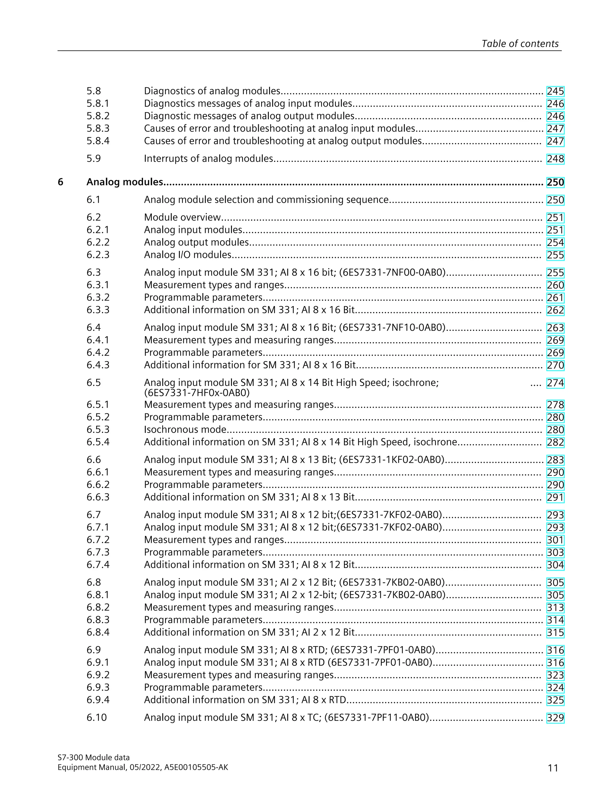
![Wiring: Thermocouple with external compensation
Insert a bridge between Comp+ and MANA when using the internal compensation.
9
'
/
0
7
6)
0ದ
0ದ
0
0
RPS
+
+
RPSದ0$1$
RPS
%DFNSODQHEXV
LQWHUIDFH
(OHFWULFDO
LVRODWLRQ
,QWHUQDO
VXSSO
,QWHUQDO
FRPSHQVDWLRQ
([WHUQDOFRPSHQVDWLRQ
1RQH
$'
XUUHQW
VRXUFH
0XOWLS
OH[HU
0HDVXULQJ
UDQJHPRGXOHV
(TXLSRWHQWLDO
ERQGLQJ
)XQFWLRQDO
JURXQG
Figure 6-18 Wiring and block diagram
Measuring range module settings
Measuring range Measuring range module setting
TC-I: Thermocouple
(internal comparison) (thermal voltage meas
urement)
TC-E: Thermocouples
(external comparison)
(thermovoltage measurement)
Type N [NiCrSi-NiSi]
Type E [NiCr-CuNi]
Type J [Fe-CuNi]
Type K [NiCr-Ni]
Type L [Fe-CuNi]
A
TC-IL: Thermocouples (linear, internal compar
ison)
(temperature measurement)
Type N [NiCrSi-NiSi]
Type E [NiCr-CuNi]
Type J [Fe-CuNi]
Type K [NiCr-Ni]
Type L [Fe-CuNi]
A
TC-EL: Thermocouples
(linear, external comparison)
(temperature measurement)
Type N [NiCrSi-NiSi]
Type E [NiCr-CuNi]
Type J [Fe-CuNi]
Type K [NiCr-Ni]
Type L [Fe-CuNi]
A
307
Analog modules
6.8 Analog input module SM 331; AI 2 x 12 Bit; (6ES7331-7KB02-0AB0)
S7-300 Module data
Equipment Manual, 05/2022, A5E00105505-AK](https://image.slidesharecdn.com/s7300moduledatamanualen-usen-us-240219101031-97f0fc5a/75/s7300_module_data_manual_en-US_en-US-pdf-307-2048.jpg)


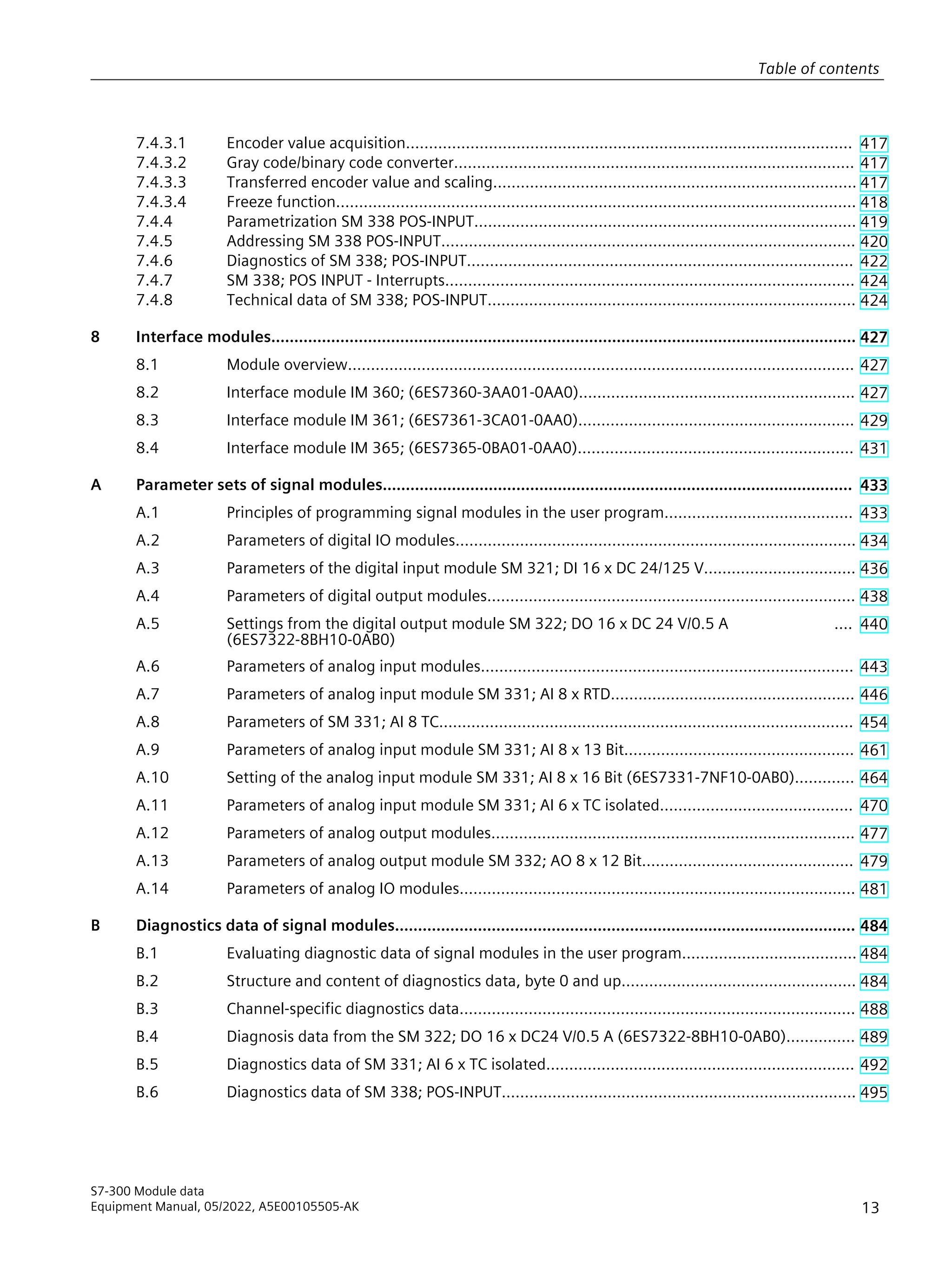
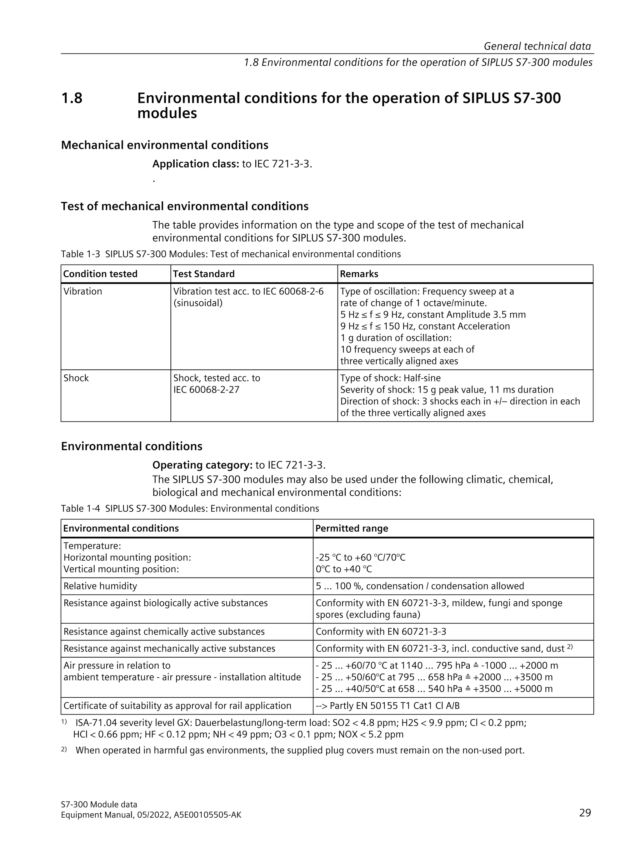
![6.8.2 Measurement types and measuring ranges
Introduction
SM 331; AI 2 x 12 Bit is equipped with a measuring range module. The measurement type
and range is configured at the measuring range parameter in STEP 7. You can use the
default voltage measurement type and ± 10 V range without having to program the
SM 331; AI 2 x 12 Bit in STEP 7.
Measuring range module
Change the position of the measuring range module to set the measurement type and range
(see the chapter Setting the measurement types and ranges of analog input channels ). The
necessary settings are also available on the module's imprint. Mark the position of the
measuring range module on the front door (see figure).
5DQJH
$ %
'
Table 6-21 Measurement types and ranges
Selected type of measurement Measuring range
(type of sensor)
Measuring range mod
ule settings
± 80 mV
± 250 mV
± 500 mV
± 1000 mV
A
V: Voltage
± 2.5 V
± 5 V
1 V to 5 V
± 10 V
B
TC-I: Thermocouple
(internal comparison) (thermal voltage meas
urement)
TC-E: Thermocouples
(external comparison)
(thermal voltage measurement)
Type N [NiCrSi-NiSi]
Type E [NiCr-CuNi]
Type J [Fe-CuNi]
Type K [NiCr-Ni]
Type L [Fe-CuNi]
A
2DMU: Current (2-wire transducer) 4 mA to 20 mA D
4DMU: Current (4-wire transducer) ± 3.2 mA
± 10 mA
0 mA to 20 mA
4 mA to 20 mA
± 20 mA
C
R-4L: Resistance
(4-wire connection)
150 Ω
300 Ω
600 Ω
A
313
Analog modules
6.8 Analog input module SM 331; AI 2 x 12 Bit; (6ES7331-7KB02-0AB0)
S7-300 Module data
Equipment Manual, 05/2022, A5E00105505-AK](https://image.slidesharecdn.com/s7300moduledatamanualen-usen-us-240219101031-97f0fc5a/75/s7300_module_data_manual_en-US_en-US-pdf-313-2048.jpg)
![Selected type of measurement Measuring range
(type of sensor)
Measuring range mod
ule settings
TC-IL: Thermocouples (linear, internal comparis
on)
(temperature measurement)
Type N [NiCrSi-NiSi]
Type E [NiCr-CuNi]
Type J [Fe-CuNi]
Type K [NiCr-Ni]
Type L [Fe-CuNi]
A
TC-EL: Thermocouples
(linear, external comparison)
(temperature measurement)
Type N [NiCrSi-NiSi]
Type E [NiCr-CuNi]
Type J [Fe-CuNi]
Type K [NiCr-Ni]
Type L [Fe-CuNi]
A
RTD-4L: Thermal resistance
(linear, 4-wire connection) (temperature meas
urement)
Pt 100 Klima
Ni 100 Klima
Pt 100 Standard
Ni 100 Standard
A
Channel groups
The two channels of SM 331; AI 2 x 12 Bit form a channel group. You can assign parameters
only to one channel group.
SM 331; AI 2 x 12 Bit is equipped with a measuring range module for channel group 0.
Line continuity check
The line continuity check is designed only for temperature measurements (thermocouples
and thermoresistors.)
Special features of the line continuity check for the 4 mA to 20 mA measuring range
If you configured a measuring range of 4 mA to 20 mA, and enabled the line continuity
check, the analog input module logs a wire-break event to diagnostics data when the current
drops below 3.6 mA.
The module also triggers a diagnostics interrupt if this function is enabled in the program.
A wire break can only be signaled by means of the lit SF LED and the diagnostic bytes must be
evaluated in the user program if diagnostics interrupts are disabled.
If you configured a measuring range of 4 mA to 20 mA, disabled the line continuity check,
and enabled diagnostic interrupts, the module triggers a diagnostic interrupt when the
underflow value is reached.
6.8.3 Programmable parameters
Introduction
For general information on programming analog modules, refer to the chapter Programming
analog modules (Page 244).
314
S7-300 Module data
Equipment Manual, 05/2022, A5E00105505-AK
Analog modules
6.8 Analog input module SM 331; AI 2 x 12 Bit; (6ES7331-7KB02-0AB0)](https://image.slidesharecdn.com/s7300moduledatamanualen-usen-us-240219101031-97f0fc5a/75/s7300_module_data_manual_en-US_en-US-pdf-314-2048.jpg)


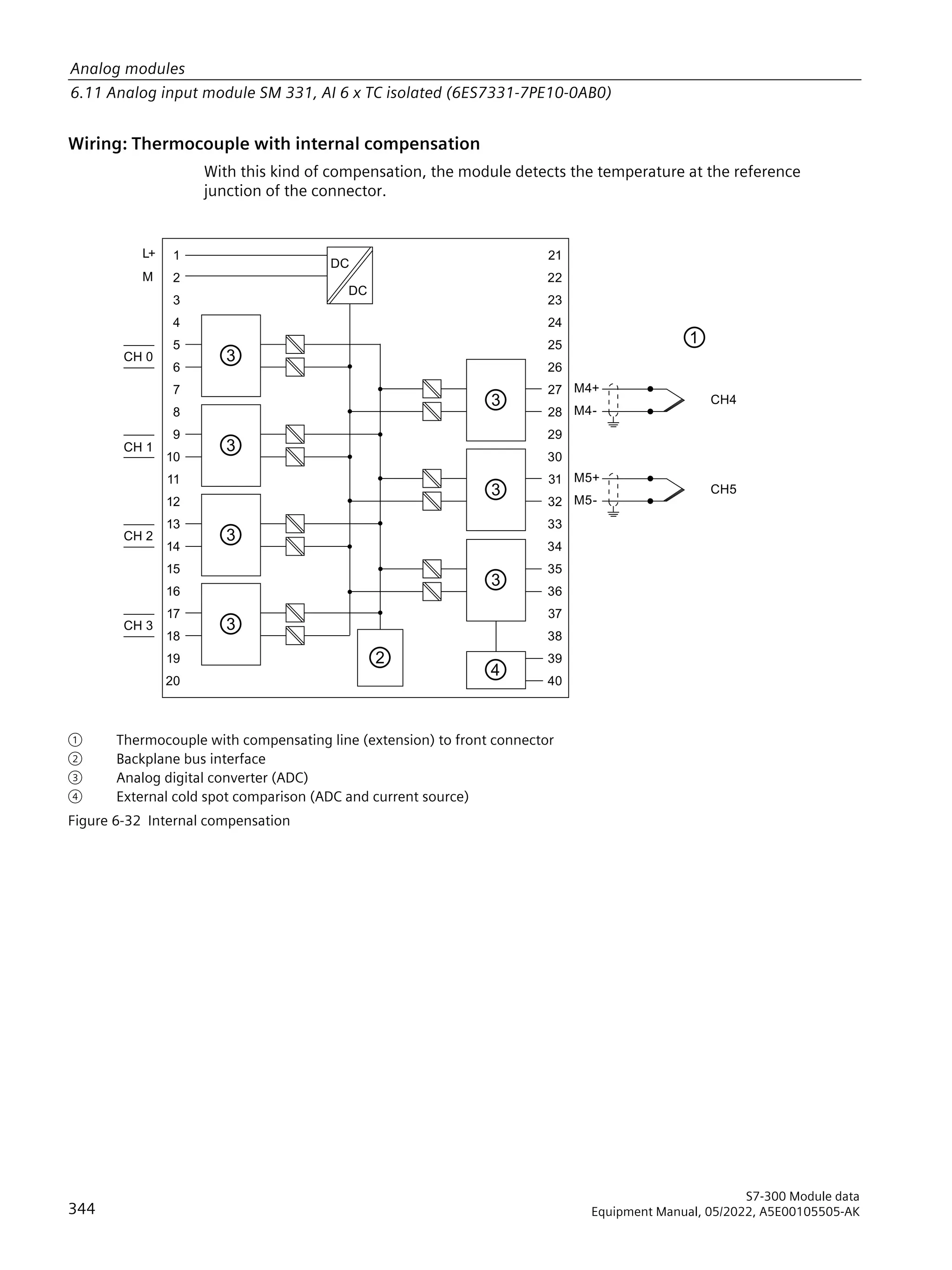


![Scaling, places
Scaling determines the position of the encoder value at the feedback interface.
• Places = 1, 2....12 indicates that appended irrelevant bits in the encoder value are shifted
out, and the encoder value is right-aligned in the address area (see the example below.)
• Places = 0 determines that appended bits are retained and available for evaluation.
This may be useful when the absolute value encoder used transfers information in the
appended bits (see manufacturer specifications) which you want to evaluate. Refer also to
chapter Gray code/binary code converter (Page 417).
Steps per revolution parameter
Up to 13 bits are available for the steps per revolution parameter. The resultant number of
steps per revolution is displayed automatically according to the Places setting.
Example of encoder value scaling
You are using a single-turn encoder with
29 steps = 512 steps per revolution (resolution/360°.)
Your configuration in STEP 7:
• Absolute encoder: 13 bits
• Scaling: 4 places
• Steps per revolution: 512
5HOHYDQWELWV
7UDQVIHUUHGELWV
'DWDGRXEOHZRUG
5HOHYDQWELWV
'DWDGRXEOHZRUG
3ULRUWRQRUPDOL]LQJFFOLFDOOPHDVXUHGHQFRGHUYDOXH
$IWHUQRUPDOL]LQJ(QFRGHUYDOXH
5HVXOWELWVWR GLJLWVPDUNHGZLWK[ ZHUHRPLWWHG
;
; ; ;
7.4.3.4 Freeze function
The freeze function freezes the actual encoder values of SM 338. The freeze function is
coupled to the digital inputs DI 0 and DI 1 of SM 338.
The freeze function is triggered by a signal transition (positive edge) a DI 0 or DI 1. Bit 31 = 1
(output address) identifies a frozen encoder value. You can freeze one, two or three encoder
values using one digital input.
Enable the freeze function by setting the corresponding parameters in STEP 7 .
To allows their event-triggered evaluation, the encoder values are retained until the freeze
function is terminated.
418
S7-300 Module data
Equipment Manual, 05/2022, A5E00105505-AK
Other signal modules
7.4 Position decoder module SM 338; POS-INPUT; (6ES7338-4BC01-0AB0)](https://image.slidesharecdn.com/s7300moduledatamanualen-usen-us-240219101031-97f0fc5a/75/s7300_module_data_manual_en-US_en-US-pdf-418-2048.jpg)


![Structure of double data word in Standard Mode
Double data word structure of the encoder inputs:
(QFRGHUYDOXHLVQRWIUR]HQ7KHYDOXHLVFRQWLQXRXVOXSGDWHG
(QFRGHUYDOXHLVIUR]HQ7KHYDOXHUHPDLQVFRQVWDQWXQWLODFNQRZOHGJHPHQW
)UHH]H
ELWHQFRGHUYDOXHLQJUDRUELQDUFRGH
Structure of double data word in Fast Mode
Double data word structure of the encoder inputs:
ELWHQFRGHUYDOXHLQJUDRUELQDUFRGH
6WDWXVGLJLWDOLQSXW
*URXSHUURU HQFRGHUHUURUHUURUH[WDX[LOLDUYROWDJH
3DUDPHWHUL]DWLRQHUURU
RSHUDWLRQDO FKHFNEDFNYDOXHVDUHYDOLG
In the double data word from channel 0, the status of digital input I0 is reported to bit 27
(digital input status) and the double data word from channel 1 is reported to digital input I1.
In the double data word from channel 2, the bit is always = 0.
Output address in Standard Mode
no output data are supported in Fast Mode.
%LW (QFRGHULQSXW
%LW (QFRGHULQSXW
%LW (QFRGHULQSXW
$FNQRZOHGJHPHQWRIIUHH]HIXQFWLRQ
0RGXOHVWDUWDGGUHVV
Reading data areas
You can read the data areas in your user program using the STEP 7 operation L PED xyz.
421
Other signal modules
7.4 Position decoder module SM 338; POS-INPUT; (6ES7338-4BC01-0AB0)
S7-300 Module data
Equipment Manual, 05/2022, A5E00105505-AK](https://image.slidesharecdn.com/s7300moduledatamanualen-usen-us-240219101031-97f0fc5a/75/s7300_module_data_manual_en-US_en-US-pdf-421-2048.jpg)


![Measurement type Code Measuring range Code
Thermal resistance + linear
ization 4-wire connection
2#1000 Pt 100 Klima
Ni 100 Klima
Pt 100 Standard range
Pt 200 Standard range
Pt 500 Standard range
Pt 1000 Standard range
Ni 1000 standard range
Pt 200 Klima
Pt 500 Klima
Pt 1000 Klima
Ni 1000 Klima
Ni 100 standard range
2#0000
2#0001
2#0010
2#0011
2#0100
2#0101
2#0110
2#0111
2#1000
2#1001
2#1001
2#1011
Thermocouples with
internal comparator
2#1010
Thermocouples with
external comparison
2#1011
Thermocouples + lineariza
tion internal comparison
2#1101
Thermocouples + lineariza
tion external comparison
2#1110
Type B [PtRh - PtRh]
Type N [NiCrSi-NiSi]
Type E [NiCr-CuNi]
Type R [PtRh -Pt]
Type S [PtRh -Pt]
Type J [Fe - CuNi IEC]
Type L [Fe-CuNi]
Type T [Cu - CuNi]
Type K [NiCr-Ni]
Type U [Cu -Cu Ni]
2#0000
2#0001
2#0010
2#0011
2#0100
2#0101
2#0110
2#0111
2#1000
2#1001
See also
Analog modules (Page 250)
A.7 Parameters of analog input module SM 331; AI 8 x RTD
Parameters
The table below shows all parameters you can set at analog input module SM 331; AI 8 x RTD.
The comparison illustrates the parameters you can edit:
• in STEP 7
• using SFC55 WR_PARM
Parameters set in STEP 7 can also be transferred to the module using SFC56 and SFC57 (refer
to the STEP 7 manuals).
Table A-9 Parameters of SM 331; AI 8 x RTD
Parameters Data record num Programmable, using ...
... SFC55 ... PG
Diagnostics: Group diagnostics no yes
Diagnostics: with wirebreak monitoring
0
no yes
Diagnostic interrupt enable yes yes
Hardware interrupt when limit exceeded yes yes
End of cycle interrupt enable yes yes
Temperature unit
1
yes yes
446
S7-300 Module data
Equipment Manual, 05/2022, A5E00105505-AK
Parameter sets of signal modules
A.7 Parameters of analog input module SM 331; AI 8 x RTD](https://image.slidesharecdn.com/s7300moduledatamanualen-usen-us-240219101031-97f0fc5a/75/s7300_module_data_manual_en-US_en-US-pdf-446-2048.jpg)


![Parameters ber Programmable, using ...
Diagnostic interrupt enable Yes Yes
Reaction to CPU STOP Yes Yes
Output type Yes Yes
Output range Yes Yes
Substitute value
1
Yes Yes
NOTE
To enable diagnostic interrupts in the user program at data record 1, you first need to enable
diagnostics at data record 0 in STEP 7.
Structure of data record 1
The figure below shows the structure of data record 1 for the parameters of analog output
modules.
You enable diagnostic interrupts by setting a logic 1 at the corresponding bit of byte 0.
%WH
%WH
%WH
%WH
%WH
%WH
%WH
%WH
%WH
%WH
%WH
%WH
%WH
%WH
5HDFWLRQWR386723
2XWSXWFKDQQHOJURXS
2XWSXWFKDQQHOJURXS
2XWSXWFKDQQHOJURXS
2XWSXWFKDQQHOJURXS
RXWSXWVDW]HURFXUUHQW
YROWDJHRU
VXEVWLWXWHYDOXH
+ROGODVWYDOXH
6HHRGLQJWDEOHIRU
WKHRXWSXWUDQJHVRIWKH
DQDORJRXWSXWPRGXOHV
KDQQHOJURXS
KDQQHOJURXS
KDQQHOJURXS
KDQQHOJURXS
2XWSXWUDQJH
KLJKEWH
ORZEWH
KLJKEWH
ORZEWH
KLJKEWH
ORZEWH
KLJKEWH
ORZEWH
2XWSXWWSH
'LDJQRVWLFLQWHUUXSWHQDEOH
6XEVWLWXWHYDOXHFKDQQHOJURXS
6XEVWLWXWHYDOXHFKDQQHOJURXS
6XEVWLWXWHYDOXHFKDQQHOJURXS
6XEVWLWXWHYDOXHFKDQQHOJURXS
478
S7-300 Module data
Equipment Manual, 05/2022, A5E00105505-AK
Parameter sets of signal modules
A.12 Parameters of analog output modules](https://image.slidesharecdn.com/s7300moduledatamanualen-usen-us-240219101031-97f0fc5a/75/s7300_module_data_manual_en-US_en-US-pdf-478-2048.jpg)

![Structure of data record 1
The figure below shows the structure of data record 1 for the parameters of SM 332; AO 8 x
12 Bit.
You enable diagnostics interrupts by setting a logic 1 at the corresponding bit of byte 0.
%WH
%WH
%WH
%WH
%WH
%WH
5HDFWLRQWR386723
2XWSXWFKDQQHO
2XWSXWFKDQQHO
2XWSXWFKDQQHO
2XWSXWFKDQQHO
%WH 2XWSXWFKDQQHO
%WH 2XWSXWFKDQQHO
%WH 2XWSXWFKDQQHO
%WH 2XWSXWFKDQQHO
2XWSXWVDW]HURFXUUHQW
YROWDJH
.HHSODVWYDOXH
KDQQHO
KDQQHO
KDQQHO
KDQQHO
KDQQHO
KDQQHO
KDQQHO
KDQQHO
6HHWKHWDEOHRIFRGHVUHODWLQJWR
RXWSXWUDQJHVRIWKH
DQDORJRXWSXWPRGXOH
60$2ၮ%LW
2XWSXWUDQJH
2XWSXWWSH
'LDJQRVWLFLQWHUUXSWHQDEOH
%WHVWRDUHQRWRFFXSLHG
Figure A-26 Data record 1 for the parameters of analog output modules
480
S7-300 Module data
Equipment Manual, 05/2022, A5E00105505-AK
Parameter sets of signal modules
A.13 Parameters of analog output module SM 332; AO 8 x 12 Bit](https://image.slidesharecdn.com/s7300moduledatamanualen-usen-us-240219101031-97f0fc5a/75/s7300_module_data_manual_en-US_en-US-pdf-480-2048.jpg)