

![Description of the motors
1.6 Rating plate data
Synchronous motors 1FK7, Generation 2
26 Configuration Manual, Edition 10/2011, 6SN1197-0AD16-0BP4
1.6 Rating plate data
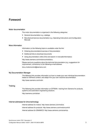
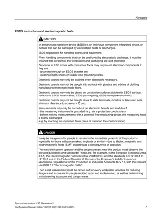
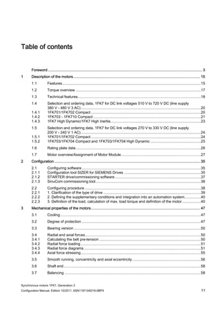
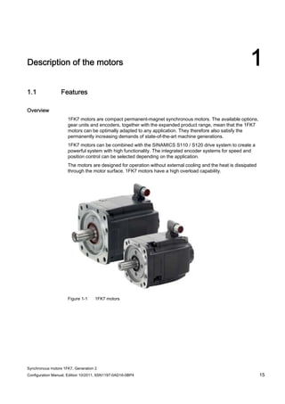
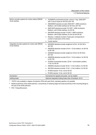
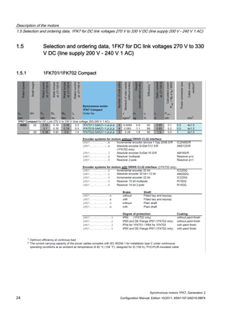
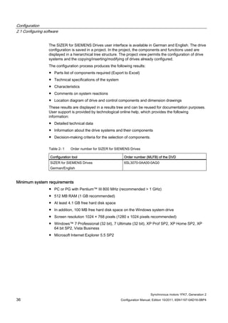
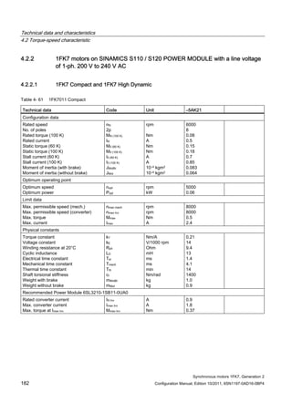
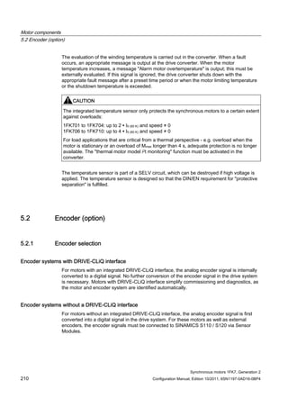
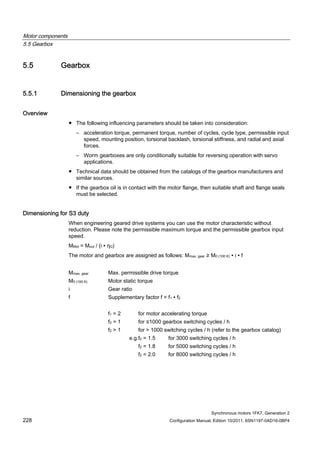
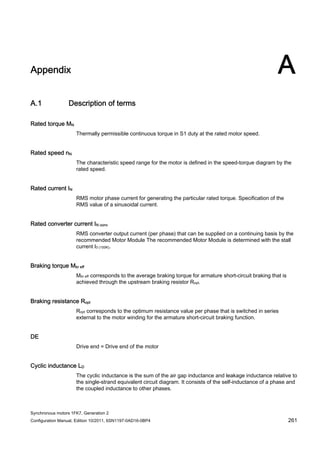
The rating plate (type plate) contains the technical data relevant for the motor. A second
rating plate is provided with the motor, and can be used for documentation purposes.
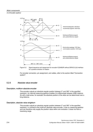
Figure 1-5 Schematic layout of rating plate
Table 1- 2 Description of the rating plate data
Position Description / technical data
1 Motor type: Synchronous motors
2 ID no., serial number
3 Static torque M0 [Nm]
4 Rated torque MN [Nm]
5 Designation of the encoder type
6 Holding brake data: Typical, voltage, power consumption
7 Standard for all rotating electrical machines
8 Production address
9 Stall current I0 [A]
10 Rated current IN [A]
11 Induced voltage at rated speed UIN [V]
12 Temperature class
13 Motor version
14 Standards and specifications
15 2D code
16 Degree of protection
17 Motor weight m [kg]
18 Rated speed nN [rpm]
19 Maximum speed nmax [rpm]
20 SIEMENS motor type/order number](https://image.slidesharecdn.com/1fk71011engen-us-130605214621-phpapp01/85/1-fk7-1011_eng_en-us-28-320.jpg)
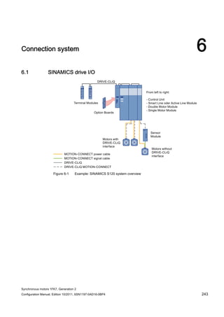
![Description of the motors
1.7 Motor overview/Assignment of Motor Module
Synchronous motors 1FK7, Generation 2
Configuration Manual, Edition 10/2011, 6SN1197-0AD16-0BP4 27
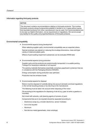
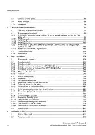
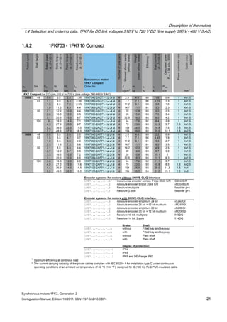
1.7 Motor overview/Assignment of Motor Module
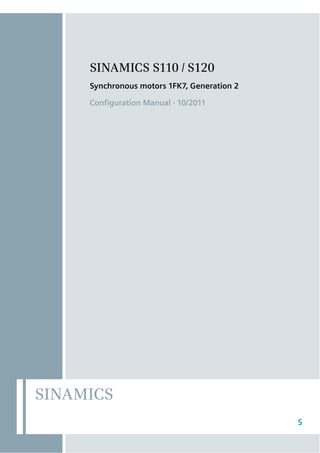
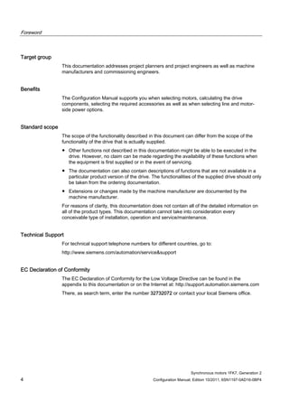
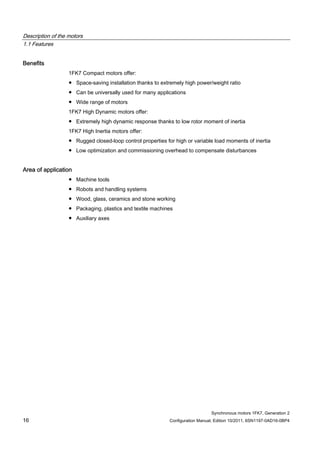
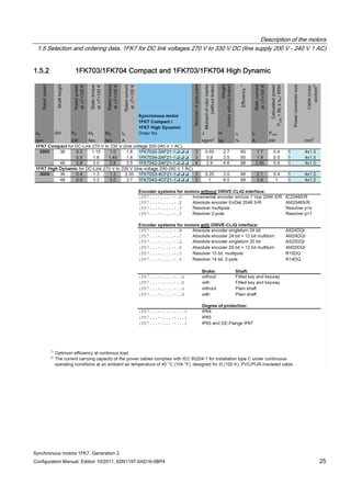
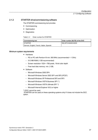
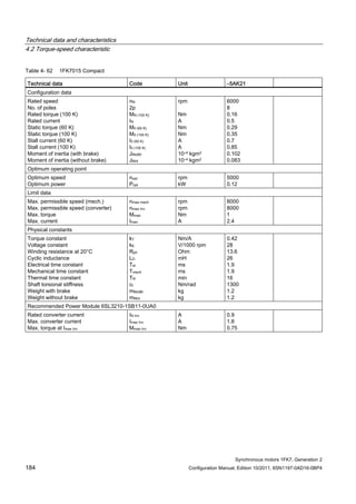
1FK7 for SINAMICS S120 Booksize, DC link voltage 510 V to 720 V DC, (line voltage 380 V to 480 V,
3 AC)
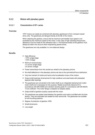
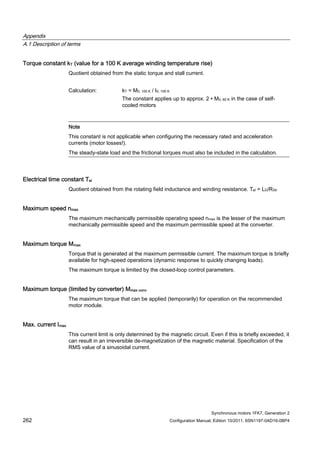
Table 1- 3 1FK7 Compact
Motor Converter: SINAMICS S120 Booksize Power cable
Order no. M0 (100K)
[Nm]
Connector size /
Cable cross-
section
Order no. IN [A] Mmax
(100K)
[Nm]
Order no.
1FK7011-5AK7 0.18 0.5 / 4x1.5 6SL312❑-❑TE13-0AA3 3 0.5 6FX5002-5DN20-❑❑❑❑
1FK7015-5AK7 0.35 0.5 / 4x1.5 6SL312❑-❑TE13-0AA3 3 1.0 6FX5002-5DN20-❑❑❑❑
1FK7022-5AK7 0.85 1 / 4x1.5 6SL312❑-❑TE13-0AA3 3 2.8 6FX❑002-5❑N01-❑❑❑❑
1FK7032-2AK7 1.15 1 / 4x1.5 6SL312❑-❑TE13-0AA3 3 4.2 6FX❑002-5❑N01-❑❑❑❑
1FK7034-2AK7 1.6 1 / 4x1.5 6SL312❑-❑TE13-0AA3 3 5.0 6FX❑002-5❑N01-❑❑❑❑
1FK7040-2AK7 1.6 1 / 4x1.5 6SL312❑-❑TE13-0AA3 3 4.0 6FX❑002-5❑N01-❑❑❑❑
1FK7042-2AC7 3.0 1 / 4x1.5 6SL312❑-❑TE13-0AA3 3 10.5 6FX❑002-5❑N01-❑❑❑❑
1FK7042-2AF7 3.0 1 / 4x1.5 6SL312❑-❑TE13-0AA3 3 8.2 6FX❑002-5❑N01-❑❑❑❑
1FK7042-2AK7 3.0 1 / 4x1.5 6SL312❑-❑TE15-0AA3 5 6.8 6FX❑002-5❑N01-❑❑❑❑
1FK7060-2AC7 6.0 1 / 4x1.5 6SL312❑-❑TE13-0AA3 3 11.4 6FX❑002-5❑N01-❑❑❑❑
1FK7060-2AF7 6.0 1 / 4x1.5 6SL312❑-❑TE15-0AA3 5 13.2 6FX❑002-5❑N01-❑❑❑❑
1FK7060-2AH7 6.0 1 - 4x1.5 6SL312❑-❑TE21-0AA3 9 15.8 6FX❑002-5❑N01-❑❑❑❑
1FK7062-2AC7 8.5 1 / 4x1.5 6SL312❑-❑TE13-0AA3 3 17.0 6FX❑002-5❑N01-❑❑❑❑
1FK7062-2AF7 8.5 1 / 4x1.5 6SL312❑-❑TE15-0AA3 5 16.0 6FX❑002-5❑N01-❑❑❑❑
1FK7062-2AH7 8.5 1 / 4x1.5 6SL312❑-❑TE21-0AA3 9 18.5 6FX❑002-5❑N01-❑❑❑❑
1FK7063-2AC7 11.0 1 / 4x1.5 6SL312❑-❑TE15-0AA3 5 20.8 6FX❑002-5❑N01-❑❑❑❑
1FK7063-2AF7 11.0 1 / 4x1.5 6SL312❑-❑TE21-0AA3 9 24.3 6FX❑002-5❑N01-❑❑❑❑
1FK7063-2AH7 11.0 1 / 4x1.5 6SL312❑-❑TE21-8AA3 18 30.9 6FX❑002-5❑N01-❑❑❑❑
1FK7080-2AF7 8.0 1 / 4x1.5 6SL312❑-❑TE15-0AA3 5 16.5 6FX❑002-5❑N01-❑❑❑❑
1FK7080-2AH7 8.0 1 / 4x1.5 6SL312❑-❑TE21-0AA3 9 18.5 6FX❑002-5❑N01-❑❑❑❑
1FK7081-2AC7 12.0 1 / 4x1.5 6SL312❑-❑TE15-0AA3 5 24.0 6FX❑002-5❑N01-❑❑❑❑
1FK7081-2AF7 12.0 1 / 4x1.5 6SL312❑-❑TE21-0AA3 9 24.7 6FX❑002-5❑N01-❑❑❑❑
1FK7081-2AH7 12.0 1 / 4x1.5 6SL312❑-❑TE21-8AA3 18 31.2 6FX❑002-5❑N01-❑❑❑❑
1FK7083-2AC7 16.0 1 / 4x1.5 6SL312❑-❑TE21-0AA3 9 36.7 6FX❑002-5❑N01-❑❑❑❑
1FK7083-2AF7 16.0 1 / 4x1.5 6SL312❑-❑TE21-8AA3 9 28.5 6FX❑002-5❑N01-❑❑❑❑
1FK7083-2AH7 16.0 1 / 4x1.5 6SL312❑-❑TE21-8AA3 18 36.7 6FX❑002-5❑N01-❑❑❑❑
1FK7084-2AC7 20.0 1 / 4x1.5 6SL312❑-❑TE21-0AA3 9 41.9 6FX❑002-5❑N01-❑❑❑❑
1FK7084-2AF7 20.0 1 / 4x1.5 6SL312❑-❑TE21-8AA3 18 55.0 6FX❑002-5❑N01-❑❑❑❑
1FK7100-2AC7 18.0 1 / 4x1.5 6SL312❑-❑TE21-0AA3 9 38.1 6FX❑002-5❑N01-❑❑❑❑
1FK7100-2AF7 18.0 1 / 4x1.5 6SL312❑-❑TE21-8AA3 18 54.0 6FX❑002-5❑N01-❑❑❑❑
1FK7101-2AC7 27.0 1.5 / 4x1.5 6SL312❑-❑TE21-8AA3 18 73.0 6FX❑002-5❑N21-❑❑❑❑
1FK7101-2AF7 27.0 1.5 / 4x2.5 6SL312❑-❑TE21-8AA3 18 52.0 6FX❑002-5❑N31-❑❑❑❑
1FK7103-2AC7 36.0 1.5 / 4x1.5 6SL312❑-❑TE21-8AA3 18 87.0 6FX❑002-5❑N21-❑❑❑❑
1FK7103-2AF7 36.0 1.5 / 4x4 6SL312❑-❑TE23-0AA3 30 77.0 6FX❑002-5❑N41-❑❑❑❑
1FK7105-2AC7 48.0 1.5 / 4x2.5 6SL312❑-❑TE23-0AA3 30 126.0 6FX❑002-5❑N31-❑❑❑❑
1FK7105-2AF7 48.0 1.5 / 4x6 6SL312❑-❑TE23-0AA3 30 87.0 6FX❑002-5❑N51-❑❑❑❑](https://image.slidesharecdn.com/1fk71011engen-us-130605214621-phpapp01/85/1-fk7-1011_eng_en-us-29-320.jpg)
![Description of the motors
1.7 Motor overview/Assignment of Motor Module
Synchronous motors 1FK7, Generation 2
28 Configuration Manual, Edition 10/2011, 6SN1197-0AD16-0BP4
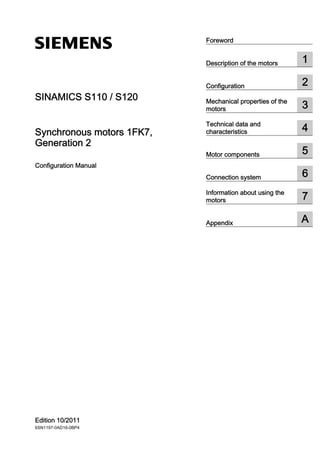
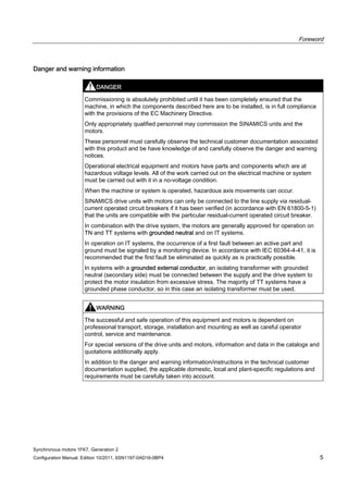
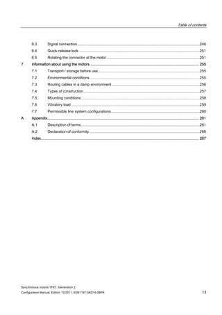
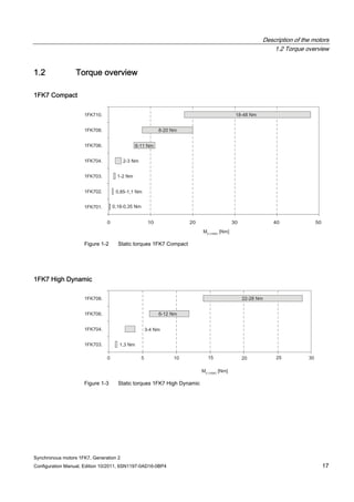
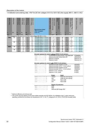
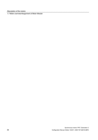
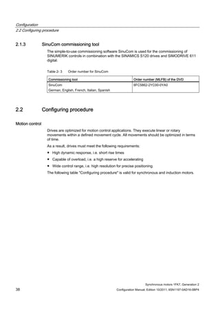
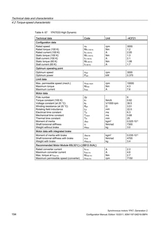
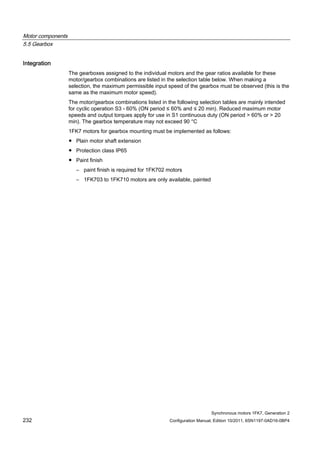
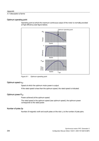
Table 1- 4 1FK7 High Inertia
Motor Converter: SINAMICS S120 Booksize Power cable
Order no. M0 (100K)
[Nm]
Connector size /
Cable cross-
section
Order no. IN [A] Mmax
(100K)
[Nm]
Order no.
1FK7042-3BK7 3.0 1 / 4x1.5 6SL312❑-❑TE15-0AA3 5 6.8 6FX❑002-5❑N01-❑❑❑❑
1FK7060-3BF7 6.0 1 / 4x1.5 6SL312❑-❑TE15-0AA3 5 13.2 6FX❑002-5❑N01-❑❑❑❑
1FK7062-3BF7 8.5 1 / 4x1.5 6SL312❑-❑TE15-0AA3 5 16.0 6FX❑002-5❑N01-❑❑❑❑
1FK7081-3BF7 12.0 1 / 4x1.5 6SL312❑-❑TE21-0AA3 9 24.7 6FX❑002-5❑N01-❑❑❑❑
1FK7084-3BC7 20.0 1 / 4x1.5 6SL312❑-❑TE21-0AA3 9 41.9 6FX❑002-5❑N01-❑❑❑❑
1FK7084-3BF7 20.0 1 / 4x1.5 6SL312❑-❑TE21-8AA3 18 55.0 6FX❑002-5❑N01-❑❑❑❑
Table 1- 5 1FK7 High Dynamic
Motor Converter: SINAMICS S120 Booksize Power cable
Order no. M0 (100K)
[Nm]
Connector size /
Cable cross-
section
Order no. IN [A] Mmax
(100K)
[Nm]
Order no.
1FK7033-4CK7 1.3 1 / 4x1.5 6SL312❑-❑TE13-0AA3 3 3.5 6FX❑002-5❑N01-❑❑❑❑
1FK7043-4CH7 3.5 1 / 4x1.5 6SL312❑-❑TE15-0AA3 5 8.3 6FX❑002-5❑N01-❑❑❑❑
1FK7043-4CK7 3.5 1 / 4x1.5 6SL312❑-❑TE21-0AA3 9 10.0 6FX❑002-5❑N01-❑❑❑❑
1FK7044-4CF7 4.5 1 / 4x1.5 6SL312❑-❑TE15-0AA3 5 11.0 6FX❑002-5❑N01-❑❑❑❑
1FK7044-4CH7 4.5 1 / 4x1.5 6SL312❑-❑TE21-0AA3 9 13.0 6FX❑002-5❑N01-❑❑❑❑
1FK7061-4CF7 6.4 1 / 4x1.5 6SL312❑-❑TE21-0AA3 9 17.0 6FX❑002-5❑N01-❑❑❑❑
1FK7061-4CH7 6.4 1 / 4x1.5 6SL312❑-❑TE21-0AA3 9 13.1 6FX❑002-5❑N01-❑❑❑❑
1FK7064-4CC7 12.0 1 / 4x1.5 6SL312❑-❑TE21-0AA3 9 26.0 6FX❑002-5❑N01-❑❑❑❑
1FK7064-4CF7 12.0 1 / 4x1.5 6SL312❑-❑TE21-8AA3 18 32.0 6FX❑002-5❑N01-❑❑❑❑
1FK7064-4CH7 12.0 1 / 4x1.5 6SL312❑-❑TE21-8AA3 18 27.5 6FX❑002-5❑N01-❑❑❑❑
1FK7085-4CC7 22.0 1 / 4x1.5 6SL312❑-❑TE21-8AA3 18 53.0 6FX❑002-5❑N01-❑❑❑❑
1FK7085-4CF7 22.0 1.5 / 4x4 6SL312❑-❑TE23-0AA3 30 51.0 6FX❑002-5❑N41-❑❑❑❑
1FK7086-4CC7 28.0 1 / 4x1.5 6SL312❑-❑TE21-8AA3 18 69.0 6FX❑002-5❑N01-❑❑❑❑
1FK7086-4CF7 28.0 1.5 / 4x4 6SL312❑-❑TE23-0AA3 30 66.0 6FX❑002-5❑N41-❑❑❑❑](https://image.slidesharecdn.com/1fk71011engen-us-130605214621-phpapp01/85/1-fk7-1011_eng_en-us-30-320.jpg)
![Description of the motors
1.7 Motor overview/Assignment of Motor Module
Synchronous motors 1FK7, Generation 2
Configuration Manual, Edition 10/2011, 6SN1197-0AD16-0BP4 29
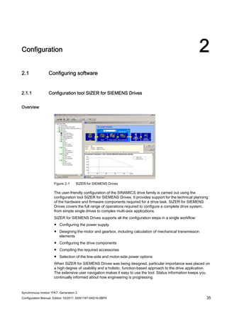
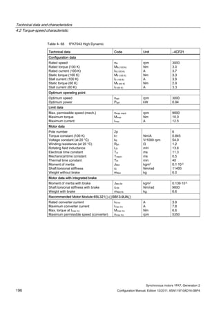
1FK7 for SINAMICS S120 Booksize Compact, DC link voltage 510 V to 720 V DC, (line voltage 380 V
to 480 V, 3 AC)
Table 1- 6 1FK7 Compact
Motor Converter:
SINAMICS S120 Booksize Compact
Power cable
Order no. M0 (100K)
[Nm]
Connector size /
Cable cross-
section
Order no. IN [A] Mmax
(100K)
[Nm]
Order no.
1FK7011-5AK7 0.18 0.5 / 4x1.5 6SL3420-❑TE13-0AA0 3 0.5 6FX5002-5DN30-❑❑❑❑
1FK7015-5AK7 0.35 0.5 / 4x1.5 6SL3420-❑TE13-0AA0 3 1.0 6FX5002-5DN30-❑❑❑❑
1FK7022-5AK7 0.85 1 / 4x1.5 6SL3420-❑TE13-0AA0 3 3.4 6FX❑002-5❑G10-❑❑❑❑
1FK7032-2AK7 1.15 1 / 4x1.5 6SL3420-❑TE13-0AA0 3 4.5 6FX❑002-5❑G10-❑❑❑❑
1FK7034-2AK7 1.6 1 / 4x1.5 6SL3420-❑TE13-0AA0 3 6.5 6FX❑002-5❑G10-❑❑❑❑
1FK7040-2AK7 1.6 1 / 4x1.5 6SL3420-❑TE13-0AA0 3 5.1 6FX❑002-5❑G10-❑❑❑❑
1FK7042-2AC7 3.0 1 / 4x1.5 6SL3420-❑TE13-0AA0 3 10.5 6FX❑002-5❑G10-❑❑❑❑
1FK7042-2AF7 3.0 1 / 4x1.5 6SL3420-❑TE13-0AA0 3 10.5 6FX❑002-5❑G10-❑❑❑❑
1FK7042-2AK7 3.0 1 / 4x1.5 6SL3420-❑TE15-0AA0 5 10.3 6FX❑002-5❑G10-❑❑❑❑
1FK7060-2AC7 6.0 1 / 4x1.5 6SL3420-❑TE13-0AA0 3 15.6 6FX❑002-5❑G10-❑❑❑❑
1FK7060-2AF7 6.0 1 / 4x1.5 6SL3420-❑TE15-0AA0 5 18.0 6FX❑002-5❑G10-❑❑❑❑
1FK7060-2AH7 6.0 1 / 4x1.5 6SL3420-1TE21-0AA0 9 18.0 6FX❑002-5❑G10-❑❑❑❑
1FK7062-2AC7 8.5 1 / 4x1.5 6SL3420-❑TE13-0AA0 3 22.4 6FX❑002-5❑G10-❑❑❑❑
1FK7062-2AF7 8.5 1 / 4x1.5 6SL3420-❑TE15-0AA0 5 21.4 6FX❑002-5❑G10-❑❑❑❑
1FK7062-2AH7 8.5 1 / 4x1.5 6SL3420-1TE21-0AA0 9 24.6 6FX❑002-5❑G10-❑❑❑❑
1FK7063-2AC7 11.0 1 / 4x1.5 6SL3420-❑TE15-0AA0 5 29.1 6FX❑002-5❑G10-❑❑❑❑
1FK7063-2AF7 11.0 1 / 4x1.5 6SL3420-1TE21-0AA0 9 33.9 6FX❑002-5❑G10-❑❑❑❑
1FK7063-2AH7 11.0 1 / 4x1.5 6SL3420-1TE21-8AA0 18 35.0 6FX❑002-5❑G10-❑❑❑❑
1FK7080-2AF7 8.0 1 / 4x1.5 6SL3420-❑TE15-0AA0 5 21.7 6FX❑002-5❑G10-❑❑❑❑
1FK7080-2AH7 8.0 1 / 4x1.5 6SL3420-1TE21-0AA0 9 24.7 6FX❑002-5❑G10-❑❑❑❑
1FK7081-2AC7 12.0 1 / 4x1.5 6SL3420-❑TE15-0AA0 5 32.9 6FX❑002-5❑G10-❑❑❑❑
1FK7081-2AF7 12.0 1 / 4x1.5 6SL3420-1TE21-0AA0 9 33.9 6FX❑002-5❑G10-❑❑❑❑
1FK7081-2AH7 12.0 1 / 4x1.5 6SL3420-1TE21-8AA0 18 37.0 6FX❑002-5❑G10-❑❑❑❑
1FK7083-2AC7 16.0 1 / 4x1.5 6SL3420-1TE21-0AA0 9 49.3 6FX❑002-5❑G10-❑❑❑❑
1FK7083-2AF7 16.0 1 / 4x1.5 6SL3420-1TE21-8AA0 18 50.0 6FX❑002-5❑G10-❑❑❑❑
1FK7083-2AH7 16.0 1 / 4x1.5 6SL3420-1TE21-8AA0 18 49.3 6FX❑002-5❑G10-❑❑❑❑
1FK7084-2AC7 20.0 1 / 4x1.5 6SL3420-1TE21-0AA0 9 58.2 6FX❑002-5❑G10-❑❑❑❑
1FK7084-2AF7 20.0 1 / 4x1.5 6SL3420-1TE21-8AA0 18 61.0 6FX❑002-5❑G10-❑❑❑❑
1FK7100-2AC7 18.0 1 / 4x1.5 6SL3420-1TE21-0AA0 9 53.3 6FX❑002-5❑G10-❑❑❑❑
1FK7100-2AF7 18.0 1 / 4x1.5 6SL3420-1TE21-8AA0 18 55.0 6FX❑002-5❑G10-❑❑❑❑
1FK7101-2AC7 27.0 1.5 / 4x1.5 6SL3420-1TE21-8AA0 18 80.0 6FX❑002-5❑G22-❑❑❑❑
1FK7101-2AF7 27.0 1.5 / 4x2.5 6SL3420-1TE21-8AA0 18 70.4 6FX❑002-5❑G32-❑❑❑❑
1FK7103-2AC7 36.0 1.5 / 4x1.5 6SL3420-1TE21-8AA0 18 108.0 6FX❑002-5❑G22-❑❑❑❑](https://image.slidesharecdn.com/1fk71011engen-us-130605214621-phpapp01/85/1-fk7-1011_eng_en-us-31-320.jpg)
![Description of the motors
1.7 Motor overview/Assignment of Motor Module
Synchronous motors 1FK7, Generation 2
30 Configuration Manual, Edition 10/2011, 6SN1197-0AD16-0BP4
Table 1- 7 1FK7 High Inertia
Motor Converter:
SINAMICS S120 Booksize Compact
Power cable
Order no. M0 (100K)
[Nm]
Connector size /
Cable cross-
section
Order no. IN [A] Mmax
(100K)
[Nm]
Order no.
1FK7042-3BK7 3.0 1 / 4x1.5 6SL3420-❑TE15-0AA0 5 10.3 6FX❑002-5❑G10-❑❑❑❑
1FK7060-3BF7 6.0 1 / 4x1.5 6SL3420-❑TE15-0AA0 5 18.0 6FX❑002-5❑G10-❑❑❑❑
1FK7062-3BF7 8.5 1 / 4x1.5 6SL3420-❑TE15-0AA0 5 21.4 6FX❑002-5❑G10-❑❑❑❑
1FK7081-3BF7 12.0 1 / 4x1.5 6SL3420-1TE21-0AA0 9 33.9 6FX❑002-5❑G10-❑❑❑❑
1FK7084-3BC7 20.0 1 / 4x1.5 6SL3420-1TE21-0AA0 9 58.2 6FX❑002-5❑G10-❑❑❑❑
1FK7084-3BF7 20.0 1 / 4x1.5 6SL3420-1TE21-8AA0 18 61.0 6FX❑002-5❑G10-❑❑❑❑
Table 1- 8 1FK7 High Dynamic
Motor Converter:
SINAMICS S120 Booksize Compact
Power cable
Order no. M0 (100K)
[Nm]
Connector size /
Cable cross-
section
Order no. IN [A] Mmax
(100K)
[Nm]
Order no.
1FK7033-4CK7 1.3 1 / 4x1.5 6SL3420-❑TE13-0AA0 3 4.3 6FX❑002-5❑G10-❑❑❑❑
1FK7043-4CH7 3.5 1 / 4x1.5 6SL3420-❑TE15-0AA0 5 10.0 6FX❑002-5❑G10-❑❑❑❑
1FK7043-4CK7 3.5 1 / 4x1.5 6SL3420-1TE21-0AA0 9 10.0 6FX❑002-5❑G10-❑❑❑❑
1FK7044-4CF7 4.5 1 / 4x1.5 6SL3420-❑TE15-0AA0 5 13.0 6FX❑002-5❑G10-❑❑❑❑
1FK7044-4CH7 4.5 1 / 4x1.5 6SL3420-1TE21-0AA0 9 13.0 6FX❑002-5❑G10-❑❑❑❑
1FK7061-4CF7 6.4 1 / 4x1.5 6SL3420-1TE21-0AA0 9 17.3 6FX❑002-5❑G10-❑❑❑❑
1FK7061-4CH7 6.4 1 / 4x1.5 6SL3420-1TE21-0AA0 9 17.3 6FX❑002-5❑G10-❑❑❑❑
1FK7064-4CC7 12.0 1 / 4x1.5 6SL3420-1TE21-0AA0 9 32.0 6FX❑002-5❑G10-❑❑❑❑
1FK7064-4CF7 12.0 1 / 4x1.5 6SL3420-1TE21-8AA0 18 32.0 6FX❑002-5❑G10-❑❑❑❑
1FK7064-4CH7 12.0 1 / 4x1.5 6SL3420-1TE21-8AA0 18 32.0 6FX❑002-5❑G10-❑❑❑❑
1FK7085-4CC7 22.0 1 / 4x1.5 6SL3420-1TE21-8AA0 18 65.0 6FX❑002-5❑G10-❑❑❑❑
1FK7086-4CC7 28.0 1 / 4x1.5 6SL3420-1TE21-8AA0 18 90.1 6FX❑002-5❑G10-❑❑❑❑
1FK7 for SINAMICS S110/S120 Power Modules PM340,
DC link voltage 510 V to 720 V DC, (line voltage 380 V to 480 V, 3AC)
Table 1- 9 1FK7 Compact
Motor Converter: SINAMICS S110 / S120
Power Module PM340
Power cable
Order no. M0 (100K)
[Nm]
Connector size /
Cable cross-
section
Order no. IN [A] Mmax
(100K)
[Nm]
Order no.
1FK7011-5AK7 0.18 0.5 / 4x1.5 6SL3210-1SE11-7UA0 1.7 0.4 6FX5002-5DN30-❑❑❑❑
1FK7015-5AK7 0.35 0.5 / 4x1.5 6SL3210-1SE11-7UA0 1.7 0.8 6FX5002-5DN30-❑❑❑❑
1FK7022-5AK7 0.85 1 / 4x1.5 6SL3210-1SE12-2UA0 2.2 2.0 6FX❑002-5❑G10-❑❑❑❑](https://image.slidesharecdn.com/1fk71011engen-us-130605214621-phpapp01/85/1-fk7-1011_eng_en-us-32-320.jpg)
![Description of the motors
1.7 Motor overview/Assignment of Motor Module
Synchronous motors 1FK7, Generation 2
Configuration Manual, Edition 10/2011, 6SN1197-0AD16-0BP4 31
Motor Converter: SINAMICS S110 / S120
Power Module PM340
Power cable
Order no. M0 (100K)
[Nm]
Connector size /
Cable cross-
section
Order no. IN [A] Mmax
(100K)
[Nm]
Order no.
1FK7032-2AK7 1.15 1 / 4x1.5 6SL3210-1SE11-7UA0 1.7 2.3 6FX❑002-5❑G10-❑❑❑❑
1FK7034-2AK7 1.6 1 / 4x1.5 6SL3210-1SE12-2UA0 2.2 3.7 6FX❑002-5❑G10-❑❑❑❑
1FK7040-2AK7 1.6 1 / 4x1.5 6SL3210-1SE13-1UA0 3.1 4.1 6FX❑002-5❑G10-❑❑❑❑
1FK7042-2AC7 3.0 1 / 4x1.5 6SL3210-1SE11-7UA0 1.7 6.4 6FX❑002-5❑G10-❑❑❑❑
1FK7042-2AF7 3.0 1 / 4x1.5 6SL3210-1SE12-2UA0 2.2 6.0 6FX❑002-5❑G10-❑❑❑❑
1FK7042-2AK7 3.0 1 / 4x1.5 6SL3210-1SE16-0❑A0 5.9 8.1 6FX❑002-5❑G10-❑❑❑❑
1FK7060-2AC7 6.0 1 / 4x1.5 6SL3210-1SE13-1UA0 3.1 11.1 6FX❑002-5❑G10-❑❑❑❑
1FK7060-2AF7 6.0 1 / 4x1.5 6SL3210-1SE16-0❑A0 5.9 14.7 6FX❑002-5❑G10-❑❑❑❑
1FK7060-2AH7 6.0 1 / 4x1.5 6SL3210-1SE17-7❑A0 7.7 13.6 6FX❑002-5❑G10-❑❑❑❑
1FK7062-2AC7 8.5 1 / 4x1.5 6SL3210-1SE13-1UA0 3.1 16.2 6FX❑002-5❑G10-❑❑❑❑
1FK7062-2AF7 8.5 1 / 4x1.5 6SL3210-1SE16-0❑A0 5.9 17.5 6FX❑002-5❑G10-❑❑❑❑
1FK7062-2AH7 8.5 1 / 4x1.5 6SL3210-1SE21-0❑A0 10.2 19.7 6FX❑002-5❑G10-❑❑❑❑
1FK7063-2AC7 11.0 1 / 4x1.5 6SL3210-1SE16-0❑A0 5.9 23.4 6FX❑002-5❑G10-❑❑❑❑
1FK7063-2AF7 11.0 1 / 4x1.5 6SL3210-1SE21-0❑A0 10.2 26.5 6FX❑002-5❑G10-❑❑❑❑
1FK7063-2AH7 11.0 1 / 4x1.5 6SL3210-1SE21-8❑A0 18 23.1 6FX❑002-5❑G10-❑❑❑❑
1FK7080-2AF7 8.0 1 / 4x1.5 6SL3210-1SE16-0❑A0 5.9 17.8 6FX❑002-5❑G10-❑❑❑❑
1FK7080-2AH7 8.0 1 / 4x1.5 6SL3210-1SE17-7❑A0 7.7 15.6 6FX❑002-5❑G10-❑❑❑❑
1FK7081-2AC7 12.0 1 / 4x1.5 6SL3210-1SE16-0❑A0 5.9 26.7 6FX❑002-5❑G10-❑❑❑❑
1FK7081-2AF7 12.0 1 / 4x1.5 6SL3210-1SE21-0❑A0 10.2 26.5 6FX❑002-5❑G10-❑❑❑❑
1FK7081-2AH7 12.0 1 / 4x1.5 6SL3210-1SE21-8❑A0 18 23.2 6FX❑002-5❑G10-❑❑❑❑
1FK7083-2AC7 16.0 1 / 4x1.5 6SL3210-1SE17-7❑A0 7.7 30.9 6FX❑002-5❑G10-❑❑❑❑
1FK7083-2AF7 16.0 1 / 4x1.5 6SL3210-1SE21-0❑A0 10.2 30.5 6FX❑002-5❑G10-❑❑❑❑
1FK7083-2AH7 16.0 1 / 4x1.5 6SL3210-1SE21-8❑A0 18 27.0 6FX❑002-5❑G10-❑❑❑❑
1FK7084-2AC7 20.0 1 / 4x1.5 6SL3210-1SE21-0❑A0 10.2 45.4 6FX❑002-5❑G10-❑❑❑❑
1FK7084-2AF7 20.0 1 / 4x1.5 6SL3210-1SE21-8❑A0 18 41.5 6FX❑002-5❑G10-❑❑❑❑
1FK7100-2AC7 18.0 1 / 4x1.5 6SL3210-1SE21-0❑A0 10.2 41.5 6FX❑002-5❑G10-❑❑❑❑
1FK7100-2AF7 18.0 1 / 4x1.5 6SL3210-1SE21-8❑A0 18 40.7 6FX❑002-5❑G10-❑❑❑❑
1FK7101-2AC7 27.0 1.5 / 4x1.5 6SL3210-1SE21-8❑A0 18 55.0 6FX❑002-5❑G22-❑❑❑❑
1FK7101-2AF7 27.0 1.5 / 4x2.5 6SL3210-1SE22-5❑A0 25 51.8 6FX❑002-5❑G32-❑❑❑❑
1FK7103-2AC7 36.0 1.5 / 4x1.5 6SL3210-1SE21-8❑A0 18 64.2 6FX❑002-5❑G22-❑❑❑❑
1FK7103-2AF7 36.0 1.5 / 4x4 6SL3210-1SE23-2❑A0 32 69.7 6FX❑002-5❑G42-❑❑❑❑
1FK7105-2AC7 48.0 1.5 / 4x2.5 6SL3210-1SE22-5❑A0 25 87.3 6FX❑002-5❑G32-❑❑❑❑
1FK7105-2AF7 48.0 1.5 / 4x6 6SL3210-1SE23-2❑A0 32 78.1 6FX❑002-5❑G52-❑❑❑❑](https://image.slidesharecdn.com/1fk71011engen-us-130605214621-phpapp01/85/1-fk7-1011_eng_en-us-33-320.jpg)
![Description of the motors
1.7 Motor overview/Assignment of Motor Module
Synchronous motors 1FK7, Generation 2
32 Configuration Manual, Edition 10/2011, 6SN1197-0AD16-0BP4
Table 1- 10 1FK7 High Inertia
Motor Converter: SINAMICS S110 / S120
Power Module PM340
Power cable
Order no. M0 (100K)
[Nm]
Connector size /
Cable cross-
section
Order no. IN [A] Mmax
(100K)
[Nm]
Order no.
1FK7042-3BK7 3.0 1 / 4x1.5 6SL3210-1SE16-0❑A0 5.9 8.1 6FX❑002-5❑G10-❑❑❑❑
1FK7060-3BF7 6.0 1 / 4x1.5 6SL3210-1SE16-0❑A0 5.9 14.7 6FX❑002-5❑G10-❑❑❑❑
1FK7062-3BF7 8.5 1 / 4x1.5 6SL3210-1SE16-0❑A0 5.9 17.5 6FX❑002-5❑G10-❑❑❑❑
1FK7081-3BF7 12.0 1 / 4x1.5 6SL3210-1SE21-0❑A0 10.2 26.5 6FX❑002-5❑G10-❑❑❑❑
1FK7084-3BC7 20.0 1 / 4x1.5 6SL3210-1SE21-0❑A0 10.2 45.4 6FX❑002-5❑G10-❑❑❑❑
1FK7084-3BF7 20.0 1 / 4x1.5 6SL3210-1SE21-8❑A0 18 41.5 6FX❑002-5❑G10-❑❑❑❑
Table 1- 11 1FK7 High Dynamic
Motor Converter: SINAMICS S110 / S120
Power Module PM340
Power cable
Order no. M0 (100K)
[Nm]
Connector size /
Cable cross-
section
Order no. IN [A] Mmax
(100K)
[Nm]
Order no.
1FK7033-4CK7 1.3 1 / 4x1.5 6SL3210-1SE12-2UA0 2.2 2.6 6FX❑002-5❑G10-❑❑❑❑
1FK7043-4CH7 3.5 1 / 4x1.5 6SL3210-1SE14-1UA0 4.1 6.8 6FX❑002-5❑G10-❑❑❑❑
1FK7043-4CK7 3.5 1 / 4x1.5 6SL3210-1SE16-0❑A0 5.9 7.1 6FX❑002-5❑G10-❑❑❑❑
1FK7044-4CF7 4.5 1 / 4x1.5 6SL3210-1SE14-1UA0 4.1 9.0 6FX❑002-5❑G10-❑❑❑❑
1FK7044-4CH7 4.5 1 / 4x1.5 6SL3210-1SE16-0❑A0 5.9 9.6 6FX❑002-5❑G10-❑❑❑❑
1FK7061-4CF7 6.4 1 / 4x1.5 6SL3210-1SE17-7❑A0 7.7 14.8 6FX❑002-5❑G10-❑❑❑❑
1FK7061-4CH7 6.4 1 / 4x1.5 6SL3210-1SE21-0❑A0 10.2 13.9 6FX❑002-5❑G10-❑❑❑❑
1FK7064-4CC7 12.0 1 / 4x1.5 6SL3210-1SE21-0❑A0 10.2 27.2 6FX❑002-5❑G10-❑❑❑❑
1FK7064-4CF7 12.0 1 / 4x1.5 6SL3210-1SE21-8❑A0 18 26.7 6FX❑002-5❑G10-❑❑❑❑
1FK7064-4CH7 12.0 1 / 4x1.5 6SL3210-1SE21-8❑A0 18 20.1 6FX❑002-5❑G10-❑❑❑❑
1FK7085-4CC7 22.0 1 / 4x1.5 6SL3210-1SE21-8❑A0 18 39.8 6FX❑002-5❑G10-❑❑❑❑
1FK7085-4CF7 22.0 1.5 / 4x4 6SL3210-1SE22-5❑A0 25 35.8 6FX❑002-5❑G42-❑❑❑❑
1FK7086-4CC7 28.0 1 / 4x1.5 6SL3210-1SE21-8❑A0 18 52.1 6FX❑002-5❑G10-❑❑❑❑
1FK7086-4CF7 28.0 1.5 / 4x4 6SL3210-1SE22-5❑A0 25 46.9 6FX❑002-5❑G42-❑❑❑❑](https://image.slidesharecdn.com/1fk71011engen-us-130605214621-phpapp01/85/1-fk7-1011_eng_en-us-34-320.jpg)
![Description of the motors
1.7 Motor overview/Assignment of Motor Module
Synchronous motors 1FK7, Generation 2
Configuration Manual, Edition 10/2011, 6SN1197-0AD16-0BP4 33
1FK7 for SINAMICS S110/S120 Power Modules PM340,
DC link voltage 270 V to 330 V DC, (line voltage 200 V to 240 V, 1AC)
Table 1- 12 1FK7 Compact
Motor Converter: SINAMICS S110 / S120
Power Module PM340
Power cable
Order no. M0 (100K)
[Nm]
Connector size /
Cable cross-
section
Order no. IN [A] Mmax
(100K)
[Nm]
Order no.
1FK7011-5AK2 0.18 0.5 / 4x1.5 6SL3210-1SB11-0❑A0 0.9 0.4 6FX5002-5DN30-❑❑❑❑
1FK7015-5AK2 0.35 0.5 / 4x1.5 6SL3210-1SB11-0❑A0 0.9 0.8 6FX5002-5DN30-❑❑❑❑
1FK7022-5AK2 0.85 1 / 4x1.5 6SL3210-1SB12-3❑A0 2.3 2.1 6FX❑002-5❑G10-❑❑❑❑
1FK7032-2AF2 1.15 1 / 4x1.5 6SL3210-1SB12-3❑A0 2.3 3.2 6FX❑002-5❑G10-❑❑❑❑
1FK7034-2AF2 1.6 1 / 4x1.5 6SL3210-1SB12-3❑A0 2.3 3.8 6FX❑002-5❑G10-❑❑❑❑
1FK7042-2AF2 3.0 1 / 4x1.5 6SL3210-1SB14-0❑A0 3.9 5.9 6FX❑002-5❑G10-❑❑❑❑
Table 1- 13 1FK7 High Dynamic
Motor Converter: SINAMICS S110 / S120
Power Module PM340
Power cable
Order no. M0 (100K)
[Nm]
Connector size /
Cable cross-
section
Order no. IN [A] Mmax
(100K)
[Nm]
Order no.
1FK7033-4CF2 1.3 1 / 4x1.5 6SL3210-1SB12-3❑A0 2.3 2.7 6FX❑002-5❑G10-❑❑❑❑
1FK7043-4CF2 3.3 1 / 4x1.5 6SL3210-1SB14-0❑A0 3.9 6.4 6FX❑002-5❑G10-❑❑❑❑](https://image.slidesharecdn.com/1fk71011engen-us-130605214621-phpapp01/85/1-fk7-1011_eng_en-us-35-320.jpg)
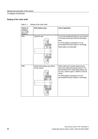
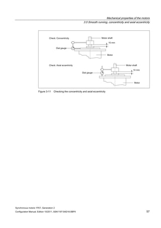
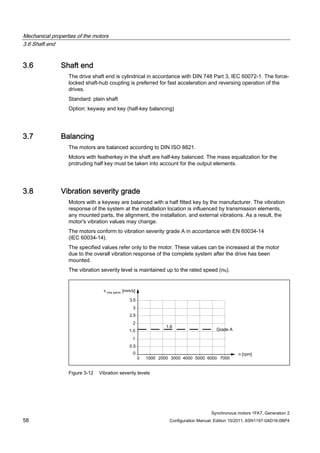
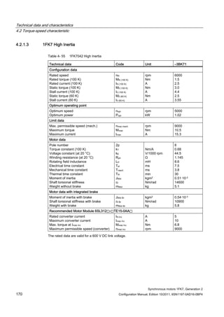
![Mechanical properties of the motors
3.3 Bearing version
Synchronous motors 1FK7, Generation 2
50 Configuration Manual, Edition 10/2011, 6SN1197-0AD16-0BP4
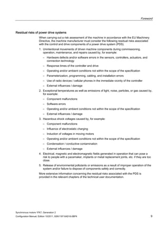
3.3 Bearing version
The 1FK7 motors are equipped with permanently lubricated deep-groove ball bearings. The
location bearing is at the DE.
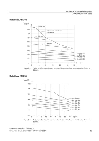
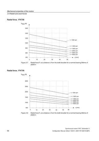
3.4 Radial and axial forces
3.4.1 Calculating the belt pre-tension
FV [N] = 2 • M0 • c / dR FV ≤ FR, perm
Table 3- 2 Explanation of the formula abbreviations
Formula
abbreviations
Unit Description
FV N Belt pre-tension
M0 Nm Motor static torque
c ––– Pre-tensioning factor: this factor is an empirical value provided
by the belt manufacturer. It can be assumed to be as follows:
for toothed belts: c = 1.5 to 2.2
for flat belts c = 2.2 to 3.0
dR m Effective diameter of the belt pulley
FR, perm N Permissible radial force
When using other configurations, the actual forces, generated from the torque being
transferred, must be taken into account.](https://image.slidesharecdn.com/1fk71011engen-us-130605214621-phpapp01/85/1-fk7-1011_eng_en-us-52-320.jpg)
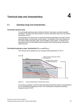
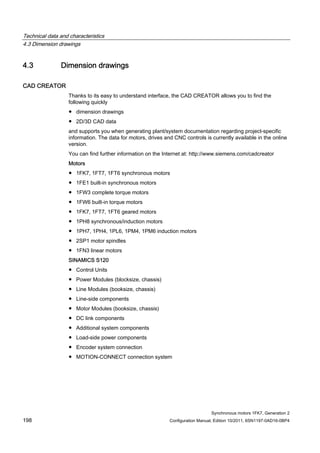
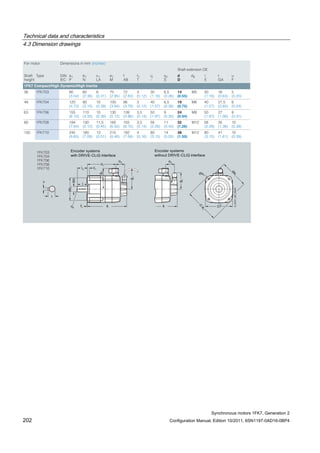
![Technical data and characteristics
4.1 Operating range and characteristics
Synchronous motors 1FK7, Generation 2
Configuration Manual, Edition 10/2011, 6SN1197-0AD16-0BP4 65
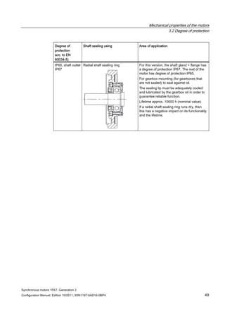
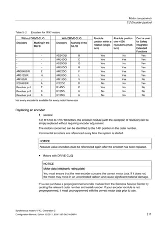
Winding versions
Several winding versions (armature circuits) for different rated speeds nN are possible within
a motor frame size.
Table 4- 3 Code letter, winding version
Rated speed nN
[RPM]
Winding version
(10. position of the Order No.)
2000 C
3000 F
4500 H
6000 K
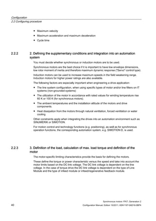
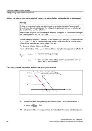
Figure 4-3 Speed-torque diagram
Note
The voltage limit characteristic of a motor with 6000 RPM rated speed lies far above that of
the same motor type with 2000 RPM. However, for the same torque, this motor requires a
significantly higher current.
For this reason, you should select the rated speed such that it does not lie too far above the
maximum speed required for the application.
The size (rating) of the Motor Module (output current) can be minimized in this fashion](https://image.slidesharecdn.com/1fk71011engen-us-130605214621-phpapp01/85/1-fk7-1011_eng_en-us-67-320.jpg)
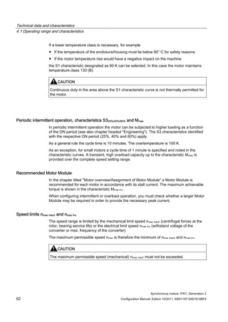
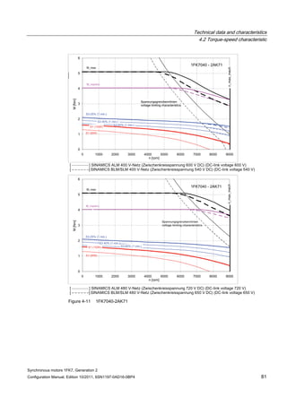
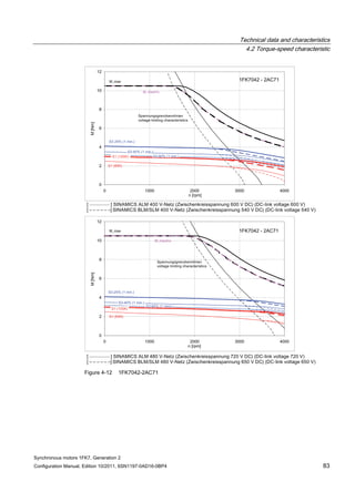
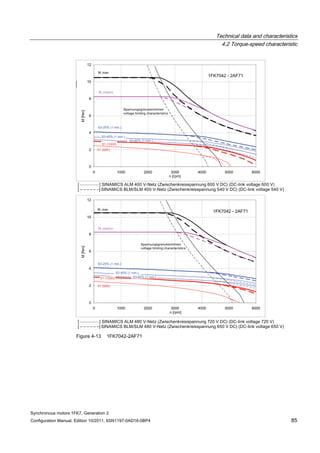
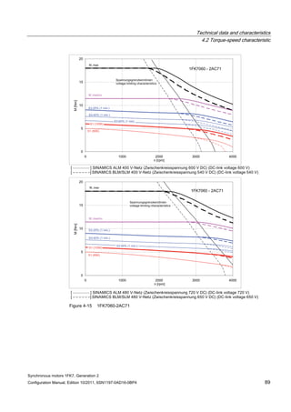
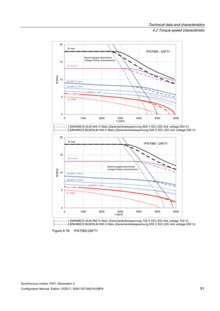
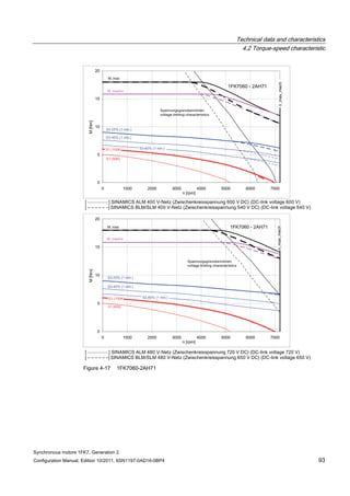
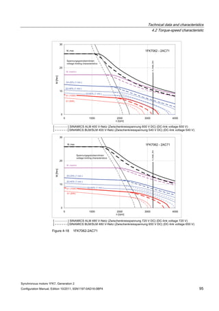
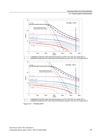
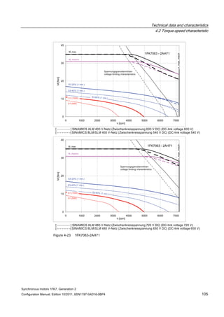
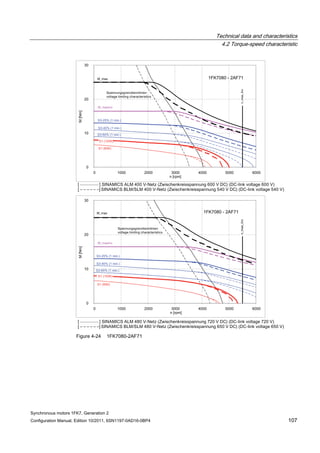
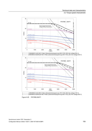
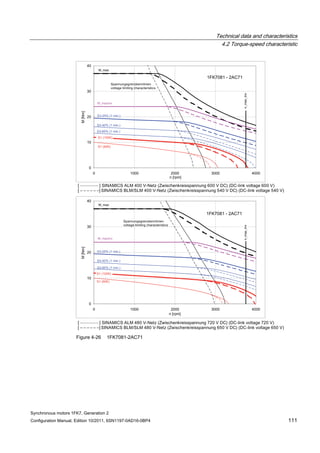
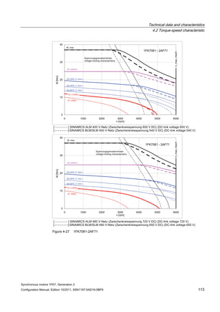
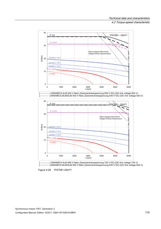
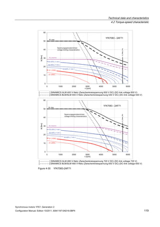
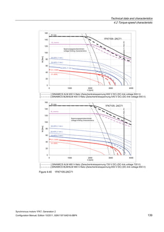
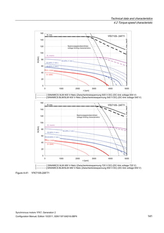
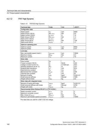
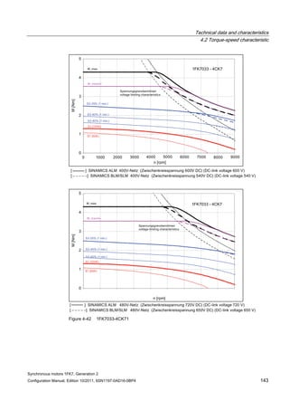
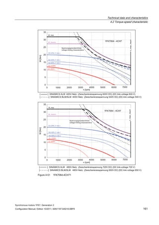
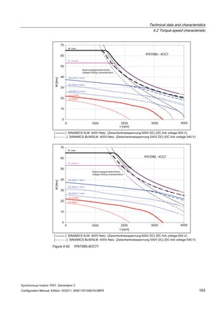
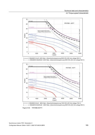
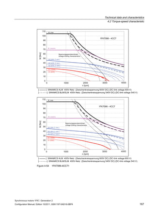
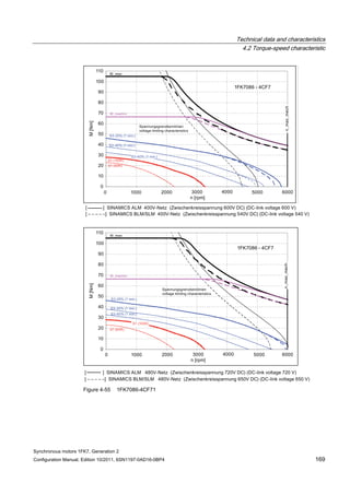
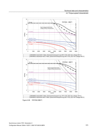
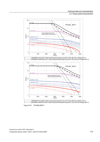
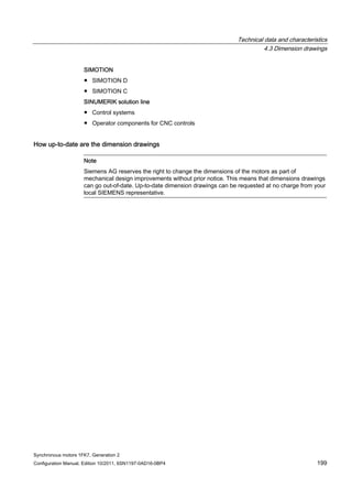
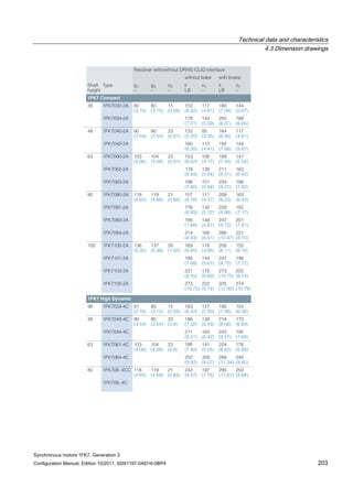
![Technical data and characteristics
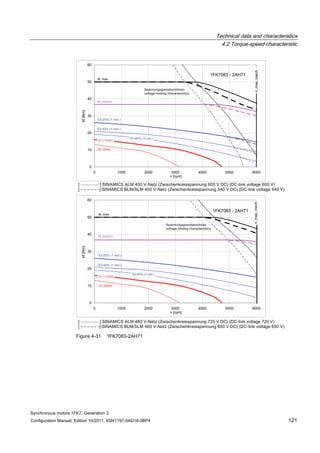
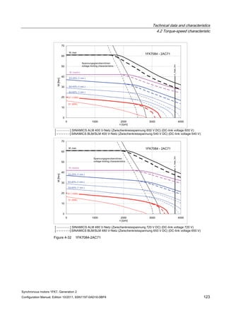
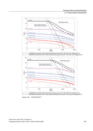
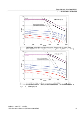
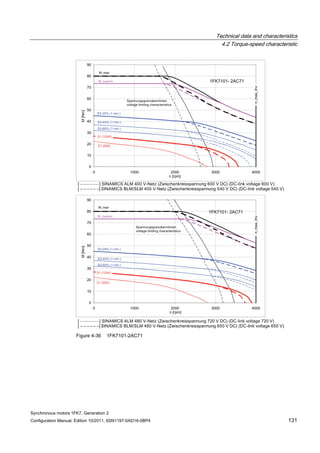
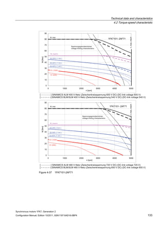
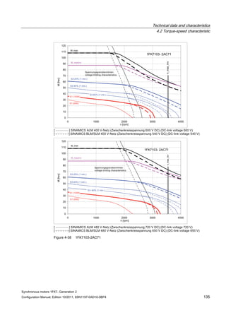
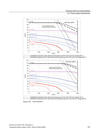
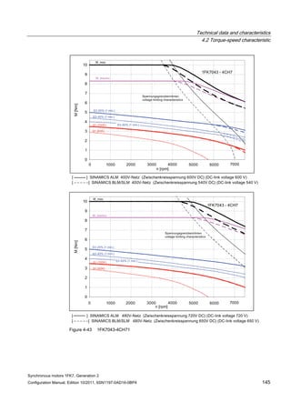
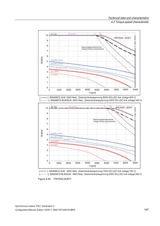
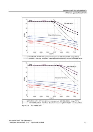
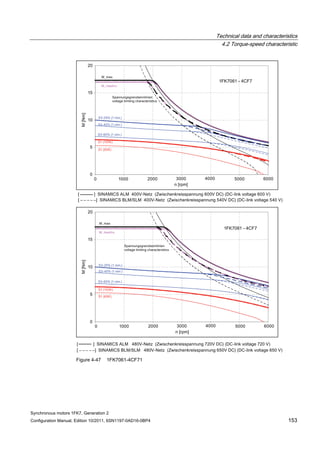
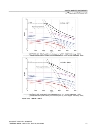
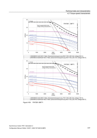
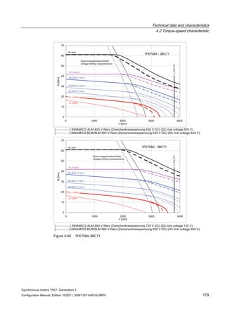
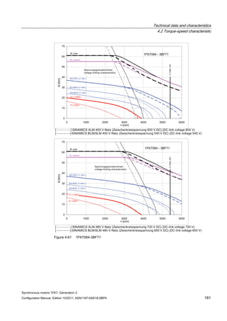
4.2 Torque-speed characteristic
Synchronous motors 1FK7, Generation 2
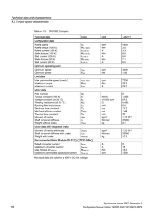
Configuration Manual, Edition 10/2011, 6SN1197-0AD16-0BP4 71
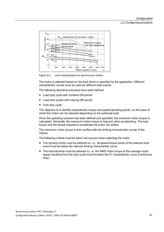
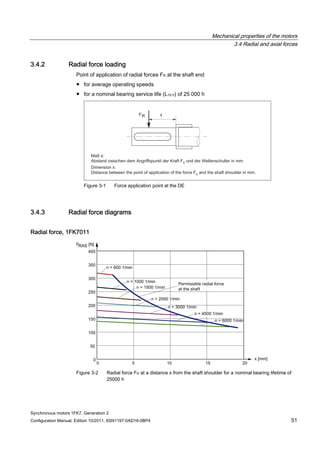
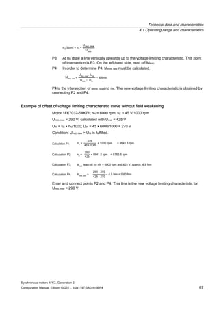
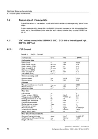
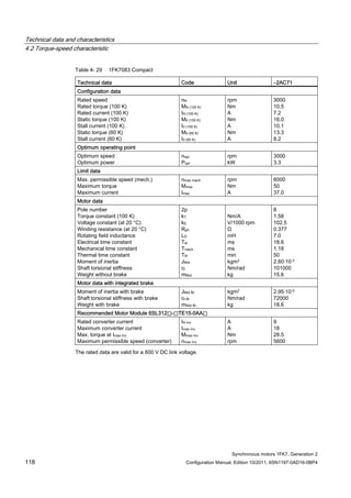
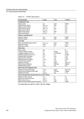
Technical data Code Unit –5AK71
Recommended Motor Module 6SL312⃞-⃞TE13-0AA⃞
Rated converter current
Maximum converter current
Max, torque at Imax Inv
Maximum permissible speed (converter)
IN Inv
Imax Inv
Mmax Inv
nmax Inv
A
A
Nm
rpm
3
6
0.5
8000
The rated data are valid for a 600 V DC link voltage.
[a] SINAMICS SLM 400 V
[b] SINAMICS ALM 400 V
[c] SINAMICS SLM 480 V
Figure 4-6 1FK7011-5AK71](https://image.slidesharecdn.com/1fk71011engen-us-130605214621-phpapp01/85/1-fk7-1011_eng_en-us-73-320.jpg)

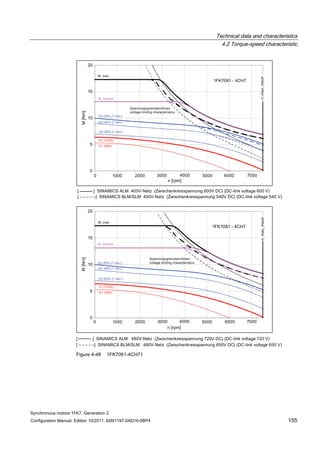
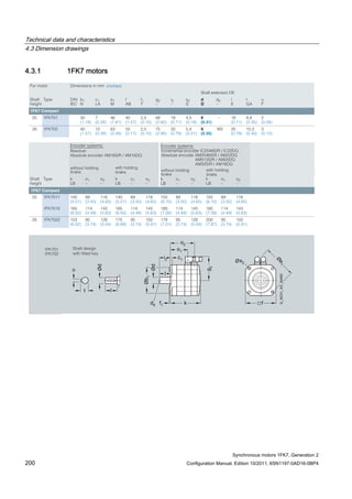
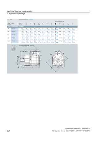
![Technical data and characteristics
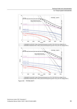
4.2 Torque-speed characteristic
Synchronous motors 1FK7, Generation 2
Configuration Manual, Edition 10/2011, 6SN1197-0AD16-0BP4 73
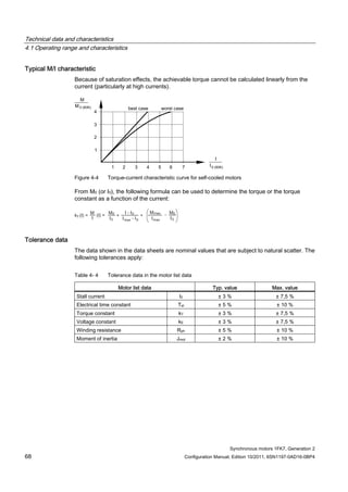
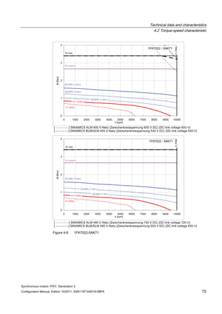
[a] SINAMICS SLM 400 V
[b] SINAMICS ALM 400 V
[c] SINAMICS SLM 480 V
Figure 4-7 1FK7015-5AK71](https://image.slidesharecdn.com/1fk71011engen-us-130605214621-phpapp01/85/1-fk7-1011_eng_en-us-75-320.jpg)


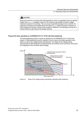
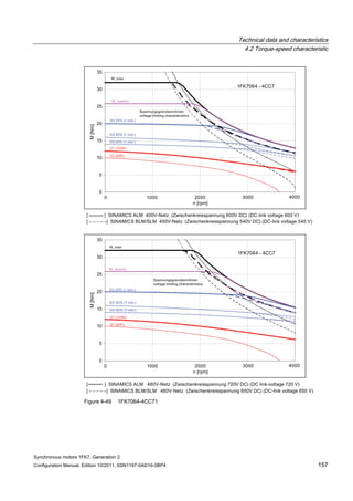
![Technical data and characteristics
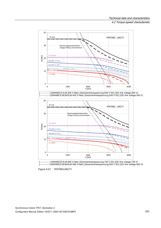
4.2 Torque-speed characteristic
Synchronous motors 1FK7, Generation 2
Configuration Manual, Edition 10/2011, 6SN1197-0AD16-0BP4 87
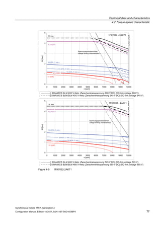
n [rpm]
Figure 4-14 1FK7042-2AK71](https://image.slidesharecdn.com/1fk71011engen-us-130605214621-phpapp01/85/1-fk7-1011_eng_en-us-89-320.jpg)


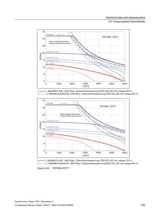
![Technical data and characteristics
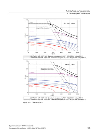
4.2 Torque-speed characteristic
Synchronous motors 1FK7, Generation 2
Configuration Manual, Edition 10/2011, 6SN1197-0AD16-0BP4 125
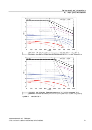
n [rpm]
Figure 4-33 1FK7084-2AF71](https://image.slidesharecdn.com/1fk71011engen-us-130605214621-phpapp01/85/1-fk7-1011_eng_en-us-127-320.jpg)


![Technical data and characteristics
4.2 Torque-speed characteristic
Synchronous motors 1FK7, Generation 2
Configuration Manual, Edition 10/2011, 6SN1197-0AD16-0BP4 183
[a] SINAMICS 1AC 230 V
Figure 4-62 1FK7011-5AK21](https://image.slidesharecdn.com/1fk71011engen-us-130605214621-phpapp01/85/1-fk7-1011_eng_en-us-185-320.jpg)
![Technical data and characteristics
4.2 Torque-speed characteristic
Synchronous motors 1FK7, Generation 2
Configuration Manual, Edition 10/2011, 6SN1197-0AD16-0BP4 185
[a] SINAMICS 1AC 230 V
Figure 4-63 1FK7015-5AK21](https://image.slidesharecdn.com/1fk71011engen-us-130605214621-phpapp01/85/1-fk7-1011_eng_en-us-187-320.jpg)

![Technical data and characteristics
4.2 Torque-speed characteristic
Synchronous motors 1FK7, Generation 2
Configuration Manual, Edition 10/2011, 6SN1197-0AD16-0BP4 187
[a] SINAMICS 1AC 230 V
Figure 4-64 1FK7022-5AK21](https://image.slidesharecdn.com/1fk71011engen-us-130605214621-phpapp01/85/1-fk7-1011_eng_en-us-189-320.jpg)

![Technical data and characteristics
4.2 Torque-speed characteristic
Synchronous motors 1FK7, Generation 2
Configuration Manual, Edition 10/2011, 6SN1197-0AD16-0BP4 189
[a] SINAMICS 1 AC 230 V
Figure 4-65 1FK7032-2AF21](https://image.slidesharecdn.com/1fk71011engen-us-130605214621-phpapp01/85/1-fk7-1011_eng_en-us-191-320.jpg)

![Technical data and characteristics
4.2 Torque-speed characteristic
Synchronous motors 1FK7, Generation 2
Configuration Manual, Edition 10/2011, 6SN1197-0AD16-0BP4 191
[a] SINAMICS 1 AC 230 V
Figure 4-66 1FK7034-2AF21](https://image.slidesharecdn.com/1fk71011engen-us-130605214621-phpapp01/85/1-fk7-1011_eng_en-us-193-320.jpg)

![Technical data and characteristics
4.2 Torque-speed characteristic
Synchronous motors 1FK7, Generation 2
Configuration Manual, Edition 10/2011, 6SN1197-0AD16-0BP4 193
[a] SINAMICS 1 AC 230 V
Figure 4-67 1FK7042-2AF21](https://image.slidesharecdn.com/1fk71011engen-us-130605214621-phpapp01/85/1-fk7-1011_eng_en-us-195-320.jpg)
![Technical data and characteristics
4.2 Torque-speed characteristic
Synchronous motors 1FK7, Generation 2
Configuration Manual, Edition 10/2011, 6SN1197-0AD16-0BP4 195
[a] SINAMICS 1 AC 230 V
Figure 4-68 1FK7033_4CF21](https://image.slidesharecdn.com/1fk71011engen-us-130605214621-phpapp01/85/1-fk7-1011_eng_en-us-197-320.jpg)
![Technical data and characteristics
4.2 Torque-speed characteristic
Synchronous motors 1FK7, Generation 2
Configuration Manual, Edition 10/2011, 6SN1197-0AD16-0BP4 197
[a] SINAMICS 1 AC 230 V
Figure 4-69 1FK7043_4CF21](https://image.slidesharecdn.com/1fk71011engen-us-130605214621-phpapp01/85/1-fk7-1011_eng_en-us-199-320.jpg)
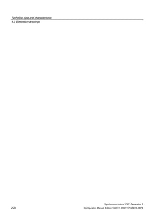
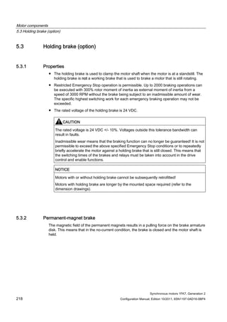
![Motor components
5.3 Holding brake (option)
Synchronous motors 1FK7, Generation 2
Configuration Manual, Edition 10/2011, 6SN1197-0AD16-0BP4 219
When 24 V DC rated voltage is connected to the brake, the solenoid – through which current
flows – establishes an opposing field. As a result the force of the permanent magnets is
neutralized and the brake opens without residual torque on account of the spring return. The
permanent magnet brake has torsion-proof connection to the rotor of the motor. This is the
reason that this brake is almost without any play.
CAUTION
Motors with integrated permanent-magnet holding brake cannot be subject to axial forces at
the shaft end! This applies when installing the system and during operation.
5.3.3 Motor-side connection of the holding brake
In combination with the MOTION CONNECT power cable with integrated brake connection
cable, the holding brake in the motor is intended for direct connection to the SINAMICS
converter. Since safe electrical isolation from the motor winding is guaranteed for the brake
cable in the motor and the power cable is designed as an enforced insulation, no further
protection circuits are required in this case.
5.3.4 Protective circuitry for the brake
The brake can be activated via an external power supply. Since safe electrical isolation from
the motor winding is guaranteed for the brake cable in the motor and the power cable is
designed as an enforced insulation, this can also be a PELV (PELV = protective extra low
voltage) supply. The relay K1, located between coil and contact, must also have enforced
insulation in order to protect the internal logic voltage.
In the case of an external activation, the brake has to be provided with a protective circuit
(see Fig. "Suggested circuit for the external power supply"). This protective circuit avoids
parasitic voltage peaks and guarantees the switching times indicated (see Table "Technical
data of holding brakes used").
The minimum voltage of 24 V DC -10% must be available at the connector on the motor side
in order to guarantee that the brake reliably opens. If the maximum voltage of 24 V DC +10%
is exceeded, the brake could re-close. The voltage drop along the brake feeder cable must
be taken into consideration. The voltage drop ΔV for copper cables can be calculated
approximately as follows:
ΔU [V] = 0.042 ∙ (l/q) ∙ Ibrake l = Cable length [m]
q = Brake core cross section [mm2]
Ibrake= Direct current of the brake [A]](https://image.slidesharecdn.com/1fk71011engen-us-130605214621-phpapp01/85/1-fk7-1011_eng_en-us-221-320.jpg)
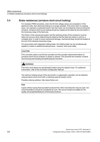
![Motor components
5.3 Holding brake (option)
Synchronous motors 1FK7, Generation 2
220 Configuration Manual, Edition 10/2011, 6SN1197-0AD16-0BP4
CAUTION
In order to avoid overvoltages when shutting down and the possible negative impact on the
plant or system environment, a protective circuit must be integrated into the feeder cable
(see figure below)
Figure 5-4 Suggested circuit for the external power supply with protective circuit
Table 5- 8 Example: Electronic components for the recommended circuit
Electr.
componen
t
Examples
F 3RV10 circuit-breaker with current paths
connected in series (if required with mounted
auxiliary contact 3RV1901 to provide a
feedback signal for the drive).
or Miniature circuit-breaker 5SX21 (if required with
mounted auxiliary contact to provide a feedback
signal for the drive).
K1 Auxiliary contactor 3RH11 or Contactor 3RT10
R2 Varistor SIOVS14K30 (EPCOS)
5.3.5 Technical data of the holding brake
Table 5- 9 Technical data of the holding brakes
Holding torque
M4
Dynamic torque
M1m
DC current Opening time
T0
Closing time
With varistor
tc1
Highest
switched energy
Motor type
[Nm] [Nm] [A] [ms] [ms] [J]
Permanent-magnet brakes for 1FK7 Compact, High Dynamic and High Inertia
1FK701☐ 0.4 0.3 0.3 30 20 2
1FK702☐ 1 0.7 0.3 30 20 8](https://image.slidesharecdn.com/1fk71011engen-us-130605214621-phpapp01/85/1-fk7-1011_eng_en-us-222-320.jpg)
![Motor components
5.3 Holding brake (option)
Synchronous motors 1FK7, Generation 2
Configuration Manual, Edition 10/2011, 6SN1197-0AD16-0BP4 221
Holding torque
M4
Dynamic torque
M1m
DC current Opening time
T0
Closing time
With varistor
tc1
Highest
switched energy
Motor type
[Nm] [Nm] [A] [ms] [ms] [J]
1FK703☐ 1.9 1 0.3 50 30 40
1FK704⃞ 4 3 0.5 70 30 150
1FK706⃞ 13 8.5 0.8 100 50 380
1FK708⃞ 22 11 0.9 200 60 1400
1FK7100 23 11 1.0 300 70 3380
1FK7101
1FK7103
1FK7105
43 25 1.0 300 70 3380
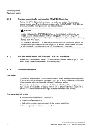
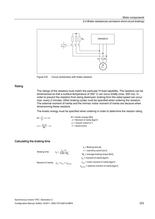
Figure 5-5 Terminology (time) for holding operation
Holding torque M4
The holding torque M4 is the highest permissible torque with which the closed brake can be
loaded in steady-state operation without slip (holding function when motor is stationary).
Dynamic braking torque M1m
The dynamic braking torque M1m is the smallest mean dynamic braking torque that can occur
for an Emergency Stop.](https://image.slidesharecdn.com/1fk71011engen-us-130605214621-phpapp01/85/1-fk7-1011_eng_en-us-223-320.jpg)
![Motor components
5.4 Brake resistances (armature short-circuit braking)
Synchronous motors 1FK7, Generation 2
Configuration Manual, Edition 10/2011, 6SN1197-0AD16-0BP4 225
The data in the following table is calculated for rated values according to the data sheet. The
variance during production as well as iron saturation have not been taken into account here.
Higher currents and torques can occur than those calculated as a result of the saturation.
1FK7 Compact
Table 5- 10 Dynamic braking for 1FK7 Compact
Average braking torque rms braking currentMotor type Braking
resistor,
external
Ropt [Ω]
Without external
braking resistor
Mbr rms [Nm]
With external
braking resistor
Mbr rms (Ropt)
[Nm]
Maximum
braking torque
Mbr max[Nm]
Without
external
braking
resistor
Ibr rms [A]
With external
braking
resistor
Ibr rms (Ropt)[A]
1FK7011-5AK71 2.3 0.13 0.14 0.17 2.5 2.3
1FK7015-5AK71 6.2 0.23 0.28 0.35 2.6 2.3
1FK7022-5AK71 4.1 1.0 1.2 1.5 5.9 5.4
1FK7032-2AK71 11.3 1.0 1.4 1.8 4.7 4.3
1FK7034-2AK71 11.8 1.5 2.2 2.7 5.8 5.3
1FK7040-2AK71 17.9 0.5 1.0 1.3 3.6 3.2
1FK7042-2AC71 18.2 1.6 2.1 2.7 2.6 2.4
1FK7042-2AF71 17.3 1.3 2.1 2.6 3.5 3.2
1FK7042-2AK71 9.7 0.8 2.1 2.6 7.1 6.4
1FK7060-2AC71 10.0 2.6 4.4 5.5 5.4 4.9
1FK7060-2AF71 8.2 2.1 4.4 5.5 7.7 6.9
1FK7060-2AH71 6.5 1.6 4.4 5.5 11.0 9.8
1FK7062-2AC71 15.5 3.6 6.6 8.2 5.4 4.9
1FK7062-2AF71 8.0 2.8 6.6 8.2 9.7 8.7
1FK7062-2AH71 5.5 2.1 6.5 8.1 14.5 13.0
1FK7063-2AC71 6.7 4.7 8.8 10.9 9.7 8.7
1FK7063-2AF71 4.7 3.7 8.8 11.0 14.6 13.1
1FK7063-2AH71 3.3 2.8 8.7 10.8 21.7 19.5
1FK7080-2AF71 9.8 2.1 5.9 7.3 8.4 7.5
1FK7080-2AH71 6.5 1.6 5.9 7.3 12.9 11.6
1FK7081-2AC71 8.6 4.1 9.3 11.6 9.0 8.1
1FK7081-2AF71 4.4 3.2 9.3 11.6 15.8 14.2
1FK7081-2AH71 3.0 2.4 9.4 11.7 23.9 21.4
1FK7083-2AC71 4.7 5.9 13.7 17.1 14.9 13.3
1FK7083-2AF71 4.0 4.6 13.8 17.1 20.2 18.1
1FK7083-2AH71 2.9 3.3 13.6 17.0 29.7 26.6
1FK7084-2AC71 4.4 7.3 17.7 21.9 17.4 15.6
1FK7084-2AF71 3.4 5.5 17.6 21.9 24.9 22.3
1FK7100-2AC71 4.8 5.2 13.8 17.1 15.0 13.4
1FK7100-2AF71 4.3 4.0 13.7 17.1 19.7 17.6](https://image.slidesharecdn.com/1fk71011engen-us-130605214621-phpapp01/85/1-fk7-1011_eng_en-us-227-320.jpg)
![Motor components
5.4 Brake resistances (armature short-circuit braking)
Synchronous motors 1FK7, Generation 2
226 Configuration Manual, Edition 10/2011, 6SN1197-0AD16-0BP4
Average braking torque rms braking currentMotor type Braking
resistor,
external
Ropt [Ω]
Without external
braking resistor
Mbr rms [Nm]
With external
braking resistor
Mbr rms (Ropt)
[Nm]
Maximum
braking torque
Mbr max[Nm]
Without
external
braking
resistor
Ibr rms [A]
With external
braking
resistor
Ibr rms (Ropt)[A]
1FK7101-2AC71 3.2 8.2 22.5 28.0 23.4 21.0
1FK7101-2AF71 2.1 6.1 22.4 27.9 36.4 32.6
1FK7103-2AC71 3.0 10.3 30.5 37.9 28.2 25.3
1FK7103-2AF71 1.4 7.9 30.6 38.0 51.4 46.0
1FK7105-2AC71 1.7 17.9 50.6 62.8 48.2 43.1
1FK7105-2AF71 1.1 13.3 50.2 62.4 70.0 66.2
Table 5- 11 Dynamic braking for 1FK7 Compact connected to a Power Module 1 AC 230 V
Average braking torque rms braking currentMotor type Braking
resistor,
external
Ropt [Ω]
Without external
braking resistor
Mbr rms [Nm]
With external
braking resistor
Mbr rms (Ropt)
[Nm]
Maximum
braking torque
Mbr max[Nm]
Without
external
braking
resistor
Ibr rms [A]
With external
braking
resistor
Ibr rms (Ropt)[A]
1FK7011-5AK21 6.9 0.13 0.14 0.17 1.4 1.3
1FK7015-5AK21 19.1 0.23 0.28 0.34 1.5 1.3
1FK7022-5AK21 4.4 1.0 1.1 1.4 5.7 5.2
1FK7032-2AF21 3.5 1.2 1.3 1.7 4.3 4.0
1FK7034-2AF21 3.3 2.1 2.2 2.8 5.9 5.5
1FK7042-2AF21 3.6 1.9 2.8 3.4 8.4 7.6
1FK7 High Dynamic
Table 5- 12 Dynamic braking for 1FK7 High Dynamic
Average braking torque rms braking currentMotor type Braking
resistor,
external
Ropt [Ω]
Without external
braking resistor
Mbr rms [Nm]
With external
braking resistor
Mbr rms (Ropt)
[Nm]
Maximum
braking torque
Mbr max[Nm]
Without
external
braking
resistor
Ibr rms [A]
With external
braking
resistor
Ibr rms (Ropt)[A]
1FK7033-4CK71 17.2 0.5 0.9 1.1 3.3 3.0
1FK7043-4CH71 8.4 1.1 2.6 3.3 7.3 6.5
1FK7043-4CK71 6.3 0.9 2.6 3.3 9.9 8.8
1FK7044-4CF71 7.4 1.7 3.4 4.2 7.0 6.3
1FK7044-4CH71 6.4 1.4 3.4 4.2 9.5 8.5](https://image.slidesharecdn.com/1fk71011engen-us-130605214621-phpapp01/85/1-fk7-1011_eng_en-us-228-320.jpg)
![Motor components
5.4 Brake resistances (armature short-circuit braking)
Synchronous motors 1FK7, Generation 2
Configuration Manual, Edition 10/2011, 6SN1197-0AD16-0BP4 227
Average braking torque rms braking currentMotor type Braking
resistor,
external
Ropt [Ω]
Without external
braking resistor
Mbr rms [Nm]
With external
braking resistor
Mbr rms (Ropt)
[Nm]
Maximum
braking torque
Mbr max[Nm]
Without
external
braking
resistor
Ibr rms [A]
With external
braking
resistor
Ibr rms (Ropt)[A]
1FK7061-4CF71 9.7 0.7 2.5 3.1 5.6 5.0
1FK7061-4CH71 7.2 0.5 2.5 3.1 8.1 7.2
1FK7064-4CC71 6.2 1.7 5.0 6.2 8.0 7.2
1FK7064-4CF71 5.3 1.3 5.1 6.3 10.8 9.7
1FK7064-4CH71 4.2 1.0 5.0 6.3 15.0 13.4
1FK7085-4CC71 3.8 3.2 10.3 12.8 14.8 13.2
1FK7085-4CF71 2.2 2.4 10.3 12.8 24.0 21.5
1FK7086-4CC71 3.1 7.4 21.3 26.5 23.2 20.7
1FK7086-4CF71 1.8 5.6 21.1 26.3 37.6 33.6
Table 5- 13 Dynamic braking for 1FK7 High Dynamic connected to a Power Module 1 AC 230 V
Average braking torque rms braking currentMotor type Braking
resistor,
external
Ropt [Ω]
Without external
braking resistor
Mbr rms [Nm]
With external
braking resistor
Mbr rms (Ropt)
[Nm]
Maximum
braking torque
Mbr max[Nm]
Without
external
braking
resistor
Ibr rms [A]
With external
braking
resistor
Ibr rms (Ropt)[A]
1FK7033-4CF21 6.9 0.7 0.9 1.1 3.3 3.0
1FK7043-4CF21 5.2 1.4 2.6 3.3 7.3 6.5
1FK7 High Inertia
Table 5- 14 Dynamic braking for 1FK7 High Inertia
Average braking torque rms braking currentMotor type Braking
resistor,
external
Ropt [Ω]
Without external
braking resistor
Mbr rms [Nm]
With external
braking resistor
Mbr rms (Ropt)
[Nm]
Maximum
braking torque
Mbr max[Nm]
Without
external
braking
resistor
Ibr rms [A]
With external
braking
resistor
Ibr rms (Ropt)[A]
1FK7042-3BK71 9.7 0.8 2.1 2.6 7.1 6.4
1FK7060-3BF71 8.2 2.1 4.4 5.5 7.7 6.9
1FK7062-3BF71 8.0 2.8 6.6 8.2 9.7 8.7
1FK7081-3BF71 4.4 3.2 9.3 11.6 15.8 14.2
1FK7084-3BC71 4.4 7.3 17.7 21.9 17.4 15.6
1FK7084-3BF71 3.4 5.5 17.6 21.9 24.9 22.3](https://image.slidesharecdn.com/1fk71011engen-us-130605214621-phpapp01/85/1-fk7-1011_eng_en-us-229-320.jpg)
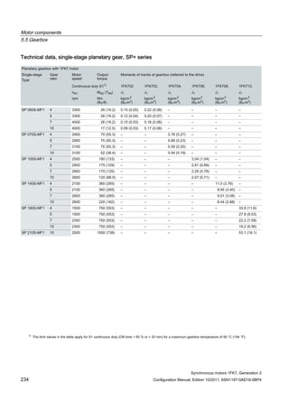
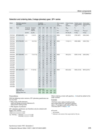
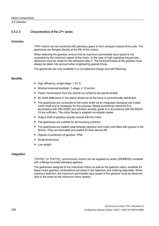
![Motor components
5.5 Gearbox
Synchronous motors 1FK7, Generation 2
Configuration Manual, Edition 10/2011, 6SN1197-0AD16-0BP4 229
NOTICE
Switching cycles can also be superimposed vibration! The supplementary factor (f2) is then
not sufficient when dimensioning the gearbox and gearboxes may fail.
The complete system should be optimized so that the higher-level vibration is minimized.
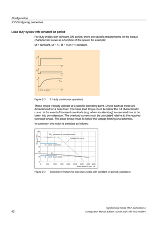
Figure 5-8 Gear ratio
The load torque and the required start-up velocity define the gearbox output torque, the
output speed and therefore the output power.
The required drive power is calculated from this:
Pout [W] = Pmot [W] ∙ ηG = (π/30) ∙ Mmot [Nm] ∙ nmot [rpm] ∙ ηG
Dimensioning for S1 duty
The gearbox itself generates heat due to friction and acts as a thermal barrier preventing
heat from being dissipated through the motor flange. This is the reason that the torque must
be reduced for S1 duty.
The required motor torque is calculated as follows:
t ( )
2
22
•1
60
•b•a=)+
•i
(=
R
kn
MMM
M
M --
MMot Motor torque [Nm]
MV Calculated "torque loss" [Nm]
a π/3 for 1FT7/1FK7 motors supplied with sinusoidal current
b Weighting factor for gearbox losses (without dimensions); b = 0.5
ηG Gearbox efficiency
i Gearbox ratio (i > 1)
kT Torque constant [Nm/A]
Mout Gearbox output torque [Nm]
nA Output speed of gearbox [rpm]
nMot Motor speed [rpm]
RStrw Resistance when hot of the motor phase [Ω]; RStrw = 1.4 • RStr (see chapter
headed "Technical data and characteristics")
Pout Gearbox output power [W]](https://image.slidesharecdn.com/1fk71011engen-us-130605214621-phpapp01/85/1-fk7-1011_eng_en-us-231-320.jpg)
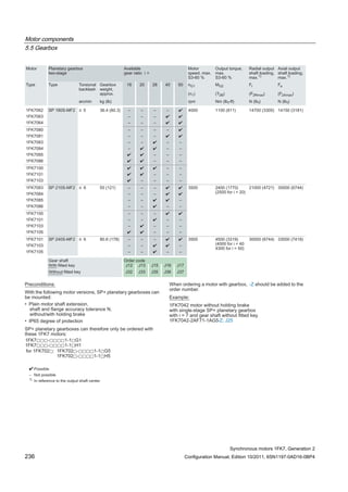
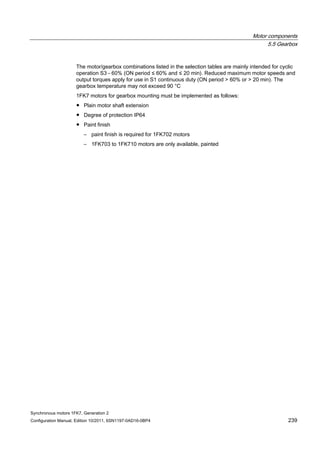
![Motor components
5.5 Gearbox
Synchronous motors 1FK7, Generation 2
230 Configuration Manual, Edition 10/2011, 6SN1197-0AD16-0BP4
PMot Motor power [W]
π pi = 3.1416
Figure 5-9 Example: 1FK7083 with angled gearbox (characteristic)
Information for additional characteristics: S1gearbox = S1100K - (S1100K - S160K) / 2
Starting behavior of a motor when a gearbox is mounted
NOTICE
During commissioning, it should be assumed that an increased current will be drawn due to
the lubrication characteristics (inadequate distribution of grease and oil) and the fact that
the shaft sealing ring is being run-in.](https://image.slidesharecdn.com/1fk71011engen-us-130605214621-phpapp01/85/1-fk7-1011_eng_en-us-232-320.jpg)
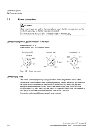
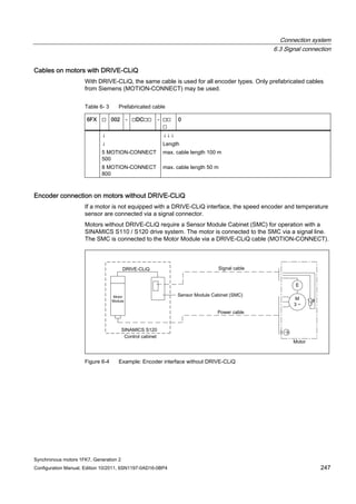
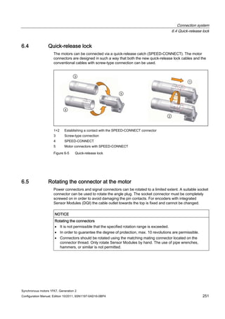
![Connection system
6.2 Power connection
Synchronous motors 1FK7, Generation 2
Configuration Manual, Edition 10/2011, 6SN1197-0AD16-0BP4 245
Current-carrying capacity for power and signal cables
The current-carrying capacity of PVC/PUR-insulated copper cables is specified for routing
types B1, B2 and C under continuous operating conditions in the table with reference to an
ambient air temperature of 40 °C. For other ambient temperatures, the values must be
corrected by the factors from the "Derating factors" table.
Table 6- 1 Cable cross section and current-carrying capacity
Cross section Current-carrying capacity rms; AC 50/60 Hz or DC for routing type
[mm2] B1 [A] B2 [A] C [A]
Electronics (according to EN 60204-1)
0.20 - 4.3 4.4
0.50 - 7.5 7.5
0.75 - 9 9.5
Power (according to EN 60204-1)
0.75 8.6 8.5 9.8
1.00 10.3 10.1 11.7
1.50 13.5 13.1 15.2
2.50 18.3 17.4 21
4 24 23 28
6 31 30 36
10 44 40 50
16 59 54 66
25 77 70 84
35 96 86 104
50 117 103 125
1) Extrapolated values
Table 6- 2 Derating factors for power and signal cables
Ambient air temperature [°C] Derating factor according to EN 60204-1 Table D1
30 1.15
35 1.08
40 1.00
45 0.91
50 0.82
55 0.71
60 0.58](https://image.slidesharecdn.com/1fk71011engen-us-130605214621-phpapp01/85/1-fk7-1011_eng_en-us-247-320.jpg)
![Synchronous motors 1FK7, Generation 2
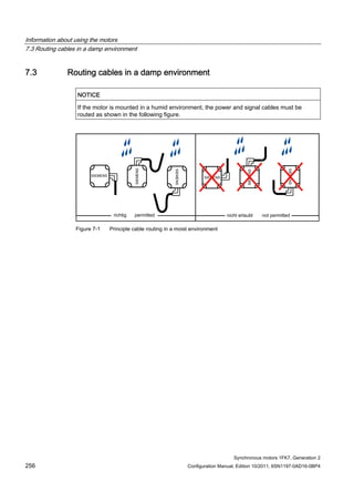
Configuration Manual, Edition 10/2011, 6SN1197-0AD16-0BP4 255
Information about using the motors 7
7.1 Transport / storage before use
The motors should be stored indoors in dry conditions with low-dust and low vibration levels
(veff < 0.2 mm/s). The motors should not be stored longer than two years at room
temperature (+5° C to +40° C) to retain the service life of the grease.
Observe the additional notes regarding transport and storage in the operating instructions.
7.2 Environmental conditions
Operating temperature range: -15° C to +40° C (without any restrictions).
All of the catalog data refer to an ambient temperature of 40° C, mounted so that the motors
are not thermally insulated and an installation altitude up to 1000 m above sea level.
Under conditions other than those specified above (ambient temperature > 40°C or
installation altitude > 1000 m above sea level), the permissible torque/power must be
determined using the factors from the following table.
Ambient temperatures and installation altitudes are rounded-off to 5° C or 500 m
respectively.
Table 7- 1 Factors to reduce the torque/power (de-rating)
Ambient temperature in ° CInstallation altitude above
sea level [m]
< 30 30 - 40 45 50 55
1000 1.07 1.00 0.96 0.92 0.87
1500 1.04 0.97 0.93 0.89 0.84
2000 1.00 0.94 0.90 0.86 0.82
2500 0.96 0.90 0.86 0.83 0.78
3000 0.92 0.86 0.82 0.79 0.75
3500 0.88 0.82 0.79 0.75 0.71
4000 0.82 0.77 0.74 0.71 0.67](https://image.slidesharecdn.com/1fk71011engen-us-130605214621-phpapp01/85/1-fk7-1011_eng_en-us-257-320.jpg)
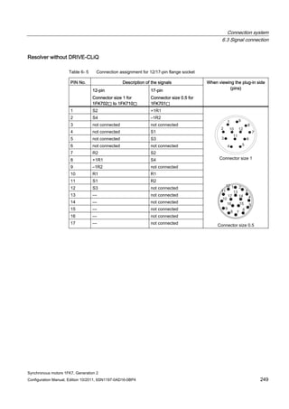
![Information about using the motors
7.5 Mounting conditions
Synchronous motors 1FK7, Generation 2
258 Configuration Manual, Edition 10/2011, 6SN1197-0AD16-0BP4
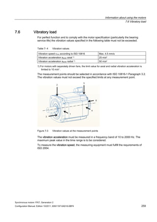
7.5 Mounting conditions
Some of the motor power loss is dissipated through the flange when the motor is connected
to the mounting flange.
Non-thermally insulated mounting
The following mounting conditions apply for the specified motor data:
Table 7- 3 Non-thermally insulated mounting conditions
Shaft height Steel plate, width x height x thickness [mm] Mounting surface[m2]
1FK701⃞ 120 x 100 x 10 0.012
1FK702⃞ to 1FK704⃞ 120 x 100 x 40 0.012
1FK706⃞ to 1FK710⃞ 450 x 370 x 30 0.17
For larger mounting surfaces, the heat dissipation conditions improve.
Thermally insulated mounting without additionally mounted components
For non-ventilated motors, the motor torque must be reduced by between 5 % and 10 %. We
recommend configuring the motor using the M0 (60 K) values. As the speed increases, the
reduction factor rises (see Fig. "Effect of the mounting conditions on the S1 characteristic").
Thermally insulated mounting with additionally mounted components
● Holding brake (integrated in the motor). No additional torque reduction required
● Gearbox; the torque has to be reduced (see Fig. "Effect of the mounting conditions on the
S1 characteristics")
Effect of thermally insulated/non-insulated mounting without and with gearbox
Figure 7-2 Effect of the mounting conditions on the S1 characteristic](https://image.slidesharecdn.com/1fk71011engen-us-130605214621-phpapp01/85/1-fk7-1011_eng_en-us-260-320.jpg)
![Appendix
A.1 Description of terms
Synchronous motors 1FK7, Generation 2
Configuration Manual, Edition 10/2011, 6SN1197-0AD16-0BP4 263
Maximum converter current Imax conv
RMS converter output current (per phase) that can be supplied temporarily by the
recommended motor module
Maximum permissible speed (mechanical) nmax.
The maximum mechanically permissible speed is nmax mech. It is defined by the centrifugal
forces and frictional forces in the bearing.
Maximum permissible speed at converter nmax conv
The maximum permissible operating speed for operation at a converter is nmax conv (e.g.
limited by withstand voltage, maximum frequency).
Mechanical time constant Tmech
The mechanical time constant is obtained from the tangent at a theoretical ramp-up function
through the origin.
Tmech = 3 ∙ RStr ∙ JMot/kT2 [s]
JMot = Servomotor moment of inertia [kgm2]
RStr = Phase resistance of the stator winding [Ohm]
kT = Torque constant [Nm/A]
NDE
Non-drive end = Non-drive end of the motor](https://image.slidesharecdn.com/1fk71011engen-us-130605214621-phpapp01/85/1-fk7-1011_eng_en-us-265-320.jpg)


This document provides information about synchronous motors from the 1FK7 generation 2 product line that are used with SINAMICS S110 and S120 drives. It describes the motor components, technical specifications, and connection systems. The document contains safety notices and warns that commissioning is prohibited until ensuring compliance with machinery directives. It also provides contact information for technical support and where to find the EC declaration of conformity.


![[Question Paper] Microprocessor and Microcontrollers (Revised Course) [April ...](https://cdn.slidesharecdn.com/ss_thumbnails/mm-qprevisedcourseapr-2015-170713044202-thumbnail.jpg?width=640&height=640&fit=bounds)