11. Safety 11
Safety
What this chapter contains
The chapter presents the warning symbols used in this manual and
the safety instructions which you must follow when installing an
optional module into a drive, converter or inverter. If ignored,
physical injury or death may follow, or damage may occur to the
equipment. Read this chapter before you start the installation.
12. 12 Safety
Use of warnings
Warnings caution you about conditions which can result in serious
injury or death and/or damage to the equipment and advise on how
to avoid the danger. The following warning symbols are used in
this manual:
Electricity warning warns of hazards from electricity
which can cause physical injury and/or damage to the
equipment.
General warning warns about conditions, other than
those caused by electricity, which can result in physical
injury and/or damage to the equipment.
13. Safety 13
Safety in installation
These warnings are intended for all who install an optional module
into a drive, converter or inverter.
WARNING! Ignoring the following instructions can cause
physical injury or death, or damage to the equipment.
• Only qualified electricians are allowed to install and maintain
the drive, converter or inverter!
• Disconnect the drive, converter or inverter into which the
module will be installed from all possible power sources. After
disconnecting, always wait for 5 minutes to let the intermediate
circuit capacitors discharge before you proceed.
• Always ensure by measuring with a multimeter (impedance at
least 1 Mohm) that:
• there is no voltage between the input power terminals of
the drive, converter or inverter and the ground
• there is no voltage between the output power terminals of
the drive, converter or inverter and the ground.
• Do not work on the control cables when power is applied to the
external control circuits of the drive, converter or inverter.
Externally supplied control circuits may carry dangerous
voltage.
15. About the manual 15
About the manual
What this chapter contains
This chapter introduces this manual.
Applicability
This manual applies to the FPBA-01 PROFIBUS DP adapter
module (+K454), SW version 2.143 or later.
Compatibility
The FPBA-01 PROFIBUS DP adapter module is compatible with
the following drives:
• ACS355
• ACSM1
• ACS850
• ACQ810
• ACS880.
The FPBA-01 PROFIBUS DP adapter module is compatible with
all master stations that support the PROFIBUS DP-V0 and DP-V1
protocols.
16. 16 About the manual
Target audience
The reader is expected to have a basic knowledge of the fieldbus
interface, electrical fundamentals, electrical wiring practices and
how to operate the drive.
Purpose of the manual
The manual provides information on installing, commissioning and
using an FPBA-01 PROFIBUS DP adapter module.
Related manuals
The related manuals are listed below.
Code (English)
Drive user’s manuals
ACS355 drives (0.37…22 kW,
0.5…30 hp) user’s manual
3AUA0000066143
Drive hardware manuals and
guides
ACSM1-204 regen supply modules
(5.3 to 61 kW) hardware manual
3AUA0000053713
ACSM1-04 drive modules (0.75 to
45 kW) hardware manual
3AFE68797543
ACSM1-04 drive modules (55 to 110
kW) hardware manual
3AFE68912130
ACSM1-04Lx liquid-cooled drive
modules (55 to 160 kW) hardware
manual
3AUA0000022083
ACS850-04 (0.37…45 kW)
hardware manual
3AUA0000045496
ACS850-04 (55…160 kW, 75…200
hp) hardware manual
3AUA0000045487
ACS850-04 (200…500 kW,
250…600 hp) hardware manual
3AUA0000026234
ACQ810-04 drive modules
(0.37…45 kW, 0.5…60 hp) hardware
manual
3AUA0000055160
ACQ810-04 drive modules (55 to
160 kW, 75 to 200 hp) hardware
manual
3AUA0000055161
17. About the manual 17
You can find manuals and other product documents in PDF format
on the Internet. See section Document library on the Internet on
the inside of the back cover. For manuals not available in the
Document library, contact your local ABB representative.
ACQ810-04 drive modules
(200…400 kW, 250…600 hp)
hardware manual
3AUA0000055155
ACS880-01 (0.55 to 250 kW, 0.75 to
350 hp) hardware manual
3AUA0000078093
Drive firmware manuals and
guides
ACSM1 motion control program
firmware manual
3AFE68848270
ACSM1 speed and torque control
program firmware manual
3AFE68848261
ACSM1 regen supply control
program firmware manual
3AUA0000052174
ACS850 standard control program
firmware manual
3AUA0000045497
ACQ810 standard pump control
program firmware manual
3AUA0000055144
ACS880 primary control program
firmware manual
3AUA0000085967
Option manuals and guides
FPBA-01 PROFIBUS DP adapter
module user’s manual
3AFE68573271
Code (English)
18. 18 About the manual
Before you start
It is assumed that the drive is installed and ready to operate before
you start the installation of the adapter module.
In addition to conventional installation tools, have the drive
manuals available during the installation as they contain important
information not included in this manual. The drive manuals are
referred to at various points of this manual.
Contents
The manual consists of the following chapters:
• Safety presents the safety instructions which you must follow
when installing a fieldbus adapter module.
• About the manual introduces this manual.
• Overview of the PROFIBUS network and the FPBA-01 module
contains a short description of the PROFIBUS network and the
adapter module.
• Mechanical installation contains a delivery checklist and
instructions on mounting the adapter module.
• Electrical installation contains instructions on cabling,
connecting the module to the PROFIBUS network and bus
termination.
• Start-up presents the steps to take during the start-up of the
drive with the adapter module and gives examples of
configuring the master system.
• Communication profiles describes the communication profiles
used in the communication between the PROFIBUS network,
the adapter module and the drive.
• Communication protocol describes the PROFIBUS messaging
used in the communication with the drive and in PROFIBUS
slave device configuration messages.
• Diagnostics explains how to trace faults with the status LEDs
on the adapter module.
19. About the manual 19
• Technical data contains the technical data of the adapter
module and the PROFIBUS link.
• Appendix A – PROFIdrive parameters contains a list of the
PROFIdrive parameters.
• Appendix B – I&M records contains the telegram and response
structures for Identification & Maintenance records.
Terms and abbreviations used in this manual
General terms and abbreviations
Term/abbreviation Explanation
Communication module Communication module is a name for a device
(eg, a fieldbus adapter) through which the drive
is connected to an external communication
network (eg, a fieldbus). The communication
with the module is activated with a drive
parameter.
Command word See Control word.
Control word 16-bit word from master to slave with bit-coded
control signals (sometimes called the
Command word).
FPBA-01 PROFIBUS
DP adapter module
One of the optional fieldbus adapter modules
available for ABB drives. FPBA-01 is a device
through which an ABB drive is connected to a
PROFIBUS network.
Parameter Operating instruction for the drive. Parameters
can be read and programmed with the drive
control panel, drive PC tools or through the
adapter module.
PLC Programmable logic controller
Profile Adaptation of the protocol for certain application
field, for example, drives.
In this manual, drive-internal profiles (eg, DCU
or FBA) are called native profiles.
Status word 16-bit word from slave to master with bit-coded
status messages
20. 20 About the manual
PROFIBUS terms
Term Explanation
Acyclic communication Communication in which messages are sent
only once on request
Array Parameter consisting of data fields of equal
data type
Broadcast Non-acknowledged message from master to all
bus participants (compare Multicast)
Cyclic communication Communication in which parameter/process
data objects are sent cyclically at predefined
intervals
Drivecast Broadcast and Multicast, a special message
frame for drives
Fault Event that leads to tripping of the device
GSD file ASCII-format device description file in a
specified form. Each different slave type on the
PROFIBUS network needs to have its own GSD
file.
Index Access reference for objects in PROFIBUS
Master Control system with bus initiative. In the
PROFIBUS terminology, master stations are
also called active stations.
Multicast Non-acknowledged message from master to
one group of bus participants (compare
Broadcast)
Name Symbolic name of a parameter
Parameter Value that can be accessed as an object, eg,
variable, constant, signal
Parameter number Parameter address
Parameter/Process Special object that contains parameter and
process
Data object Special object that contains parameter and
process data
21. About the manual 21
PROFIBUS abbreviations
The text in italics is the original German term.
Process data Data that contains Control word and reference
value or Status word and actual value. May also
contain other (user-definable) control
information.
Request label Coded information specifying the required
service for the parameter part sent from master
to slave
Response label Coded information specifying the required
service for the parameter part sent from slave to
master
Slave Passive bus participant. In the PROFIBUS
terminology, slave stations (or slaves) are also
called passive stations. Also referred to as
node.
Warning Signal caused by an existing alarm which does
not lead to tripping of the device
Abbreviation Explanation
ACT Actual value
Istwert
AK Request label/Response label
Auftragskennung/Antwortkennung
DP Decentralised Periphery
Dezentrale Peripherie
DP-V0 PROFIBUS DP extension to the EN 50170
standard, providing the basic functionality of DP,
including cyclic data exchange
DP-V1 PROFIBUS DP extension to the EN 50170
standard, including, eg, acyclic data exchange
FMS Fieldbus Message Specification
ISW See ACT.
Term Explanation
22. 22 About the manual
PA Process Automation
Prozessautomatisierung
PD Process data
Prozessdaten
PKE Parameter identification
Parameter-Kennung
PKW Parameter identification value
Parameter-Kennung-Wert
PNU Parameter number
Parameternummer
PPO Parameter/Process data object
Parameter-/Prozessdaten-Objekt
PWE Parameter value
Parameter-Wert
PZD See PD.
PZDO Process data object
Prozessdatenobjekt
SAP Service access point
SOW Reference
Sollwert
SPM Request signal
Spontanmeldung
STW Control word
Steuerwort
ZSW Status word
Zustandswort
Abbreviation Explanation
23. Overview of the PROFIBUS network and the FPBA-01 module 23
Overview of the PROFIBUS
network and the FPBA-01
module
What this chapter contains
This chapter contains a short description of the PROFIBUS
network and the FPBA-01 PROFIBUS DP adapter module.
PROFIBUS network
PROFIBUS is an open serial communication standard that enables
data exchange between all kinds of automation components.
There are three main variations of PROFIBUS:
• PROFIBUS FMS (Fieldbus Message Specification)
• PROFIBUS DP (Decentralised Periphery)
• PROFIBUS PA (Process Automation).
The physical transmission medium of the bus is a twisted pair
cable (according to the RS-485 standard). The maximum length of
the bus cable is 100 to 1200 meters, depending on the selected
transmission rate (see chapter Technical data). Up to 32 nodes can
be connected to the same PROFIBUS network segment without
the use of repeaters. With repeaters, it is possible to connect 126
nodes (including repeaters and a master station) to the network.
24. 24 Overview of the PROFIBUS network and the FPBA-01 module
In PROFIBUS communication, the master station – usually a
programmable logic controller (PLC) – polls the nodes which
respond and take the actions requested by the master. It is also
possible to send a command to several nodes at the same
broadcast; in this case the nodes do not send a response message
to the master.
The PROFIBUS protocol family is specified in the IEC 61158
standard. The communication with a drive is defined in
PROFIdrive-PROFILE – The PROFIBUS Profile for Adjustable
Speed Drives. For further information on PROFIBUS, refer to the
above-mentioned standard.
25. Overview of the PROFIBUS network and the FPBA-01 module 25
Example topology of the PROFIBUS link
An example of an allowable topology is shown below.
PROFIBUS
master
Segment 1
Segment 2
Segment 3
R
Other slave
device
Other slave
device
Other slave
device
R = Repeater
T = Termination
T T
T
ABB drive
T
ABB drive
ABB drive
T
R
T
26. 26 Overview of the PROFIBUS network and the FPBA-01 module
FPBA-01 PROFIBUS DP adapter module
The FPBA-01 PROFIBUS DP adapter module is an optional
device for ABB drives which enables the connection of the drive to
a PROFIBUS network. The drive is considered a slave on the
PROFIBUS network.
Through the adapter module you can:
• give control commands to the drive (for example, Start, Stop,
Run enable)
• feed a motor speed or torque reference to the drive
• give a process actual value or a process reference to the PID
controller of the drive
• read status information and actual values from the drive
• change drive parameter values
• reset a drive fault.
The PROFIBUS commands and services supported by the adapter
module are described in chapter Communication protocol. Refer to
the user documentation of the drive as to which commands are
supported by the drive.
The adapter module is mounted into an option slot on the motor
control board of the drive. See the drive manuals for module
placement options.
27. Overview of the PROFIBUS network and the FPBA-01 module 27
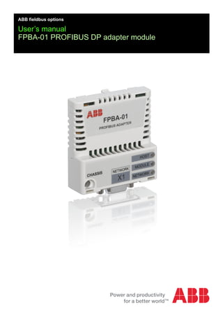
Layout of the adapter module
Diagnostic LEDs
(see chapter Diagnostics)
Bus connector X1
(see chapter Electrical
installation)Mounting screw
28. 28 Overview of the PROFIBUS network and the FPBA-01 module
29. Mechanical installation 29
Mechanical installation
What this chapter contains
This chapter contains a delivery checklist and instructions on
mounting the adapter module.
WARNING! Follow the safety instructions given in this
manual and the drive documentation.
Delivery check
The option package for the adapter module contains:
• PROFIBUS DP adapter module, type FPBA-01
• this manual.
30. 30 Mechanical installation
Mounting the adapter module
The adapter module is to be inserted into its specific position in the
drive. The module is held in place with plastic pins and one screw.
The screw also provides the electrical connection between the
module and drive frame for cable shield termination.
When the module is installed, the signal and power connection to
the drive is made through a 20-pin connector. (All drives do not use
all the available signals so the connector on the drive may have
fewer pins.)
Mounting procedure:
1. Insert the module carefully into its position on the drive.
2. Fasten the screw.
Note: It is essential to install the screw properly to fulfill the EMC
requirements and to ensure the proper operation of the module.
For more information on mounting, see the drive manuals.
31. Electrical installation 31
Electrical installation
What this chapter contains
This chapter contains:
• general cabling instructions
• instructions on connecting the module to the PROFIBUS DP
network
• instructions on switching on the bus termination.
WARNING! Before installation, switch off the drive power
supply. Wait five minutes to ensure that the capacitor bank
of the drive is discharged. Switch off all dangerous
voltages connected from external control circuits to the inputs and
outputs of the drive.
General cabling instructions
• Arrange the bus cables as far away from the motor cables as
possible.
• Avoid parallel runs.
• Use bushings at cable entries.
32. 32 Electrical installation
Connecting the module to the PROFIBUS network
Connect the bus cable to connector X1 on the adapter module.
The connector pin allocation described below follows the
PROFIBUS standard.
X1 Description
1 SHLD Alternate cable shield connection. Connected to
connector housing.
2 Not used
3 B Data positive (Conductor 1 in twisted pair)
4 RTS Request to send
5 GND_B Isolated ground
6 +5V_B Isolated 5 V DC voltage supply (30 mA max.)
7 Not used
8 A Data negative (Conductor 2 in twisted pair)
9 Not used
Housing SHLD PROFIBUS cable shield. Internally connected to
GND_B via an RC filter and directly to CH_GND
(chassis).
+5V_B and GND_B are used for bus termination.
RTS is used in some equipment to determine the direction of transmission.
In typical applications, only the line A, line B and shield are used.
X1
1
69
5
33. Electrical installation 33
It is recommended to use a PROFIBUS-approved D-SUB 9
connector. These connectors have a built-in termination network
and inductors for station capacitance compensation.
Connect the cable to the D-SUB connector as follows:
1A 1B 2A 2B
Red
Red
Green
Green
OUT
IN
Grounding (earthing) clamp/
Strain relief
34. 34 Electrical installation
Switching on the bus termination
Bus termination is required to prevent signal reflections from the
bus cable ends. The adapter module is not equipped with internal
bus termination. Therefore, the D-SUB connectors at the first and
last modules of the bus must have built-on termination switched on
as shown in the diagram below.
The adapter module is able to supply power for an active-type
termination circuitry (30 mA max.).
Note: Further information on PROFIBUS wiring is available from
the publication PROFIBUS RS 485-IS User and Installation
Guideline (www.profibus.com, order no. 2.262).
PROFIBUS
device
ON
PROFIBUS
device
OFF
PROFIBUS
device
ON
PROFIBUS
device
OFF
Term. Term. Term. Term.
35. Start-up 35
Start-up
What this chapter contains
This chapter contains:
• information on configuring the drive for operation with the
adapter module
• drive-specific instructions on starting up the drive with the
adapter module
• examples of configuring the master station for communication
with the adapter module.
WARNING! Follow the safety instructions given in this
manual and the drive documentation.
36. 36 Start-up
Drive configuration
The following information applies to all drive types compatible with
the adapter module, unless otherwise stated.
PROFIBUS connection configuration
After the adapter module has been mechanically and electrically
installed according to the instructions in chapters Mechanical
installation and Electrical installation, the drive must be prepared
for communication with the module.
The detailed procedure of activating the module for PROFIBUS DP
communication with the drive depends on the drive type. Normally,
a parameter must be adjusted to activate the communication. See
the drive-specific start-up procedures starting on page 48.
Once communication between the drive and the adapter module
has been established, several configuration parameters are copied
to the drive. These parameters are shown in the tables below and
must be checked first and adjusted where necessary.
Note that not all drives display descriptive names for the
configuration parameters. To help you identify the parameters in
different drives, the names displayed by each drive are given in
grey boxes in the tables.
Note: The new settings take effect only when the adapter module
is powered up the next time or when the fieldbus adapter refresh
parameter is activated.
Note: To ensure proper operation of the adapter module with the
drive, also set the extended Parameter Data (see SAP 61
(Set_Prm) on page 103).
Data transfer rates supported
The FPBA-01 module supports the following PROFIBUS
communication speeds: 9.6 kbit/s, 19.2 kbit/s, 45.45 kbit/s,
93.75 kbit/s, 187.5 kbit/s, 500 kbit/s, 1.5 Mbit/s, 3 Mbit/s, 6 Mbit/s,
12 Mbit/s.
The module automatically detects the communication speed and
telegram type used.
37. Start-up 37
FPBA-01 configuration parameters – group A (group 1)
Note: The actual parameter group number depends on the drive
type. Group A (group 1) corresponds to:
• parameter group 51 in ACS355, ACSM1, ACS850 and
ACQ810
• parameter group 51 in ACS880 if the adapter is installed as
fieldbus adapter A or group 54 if the adapter is installed as
fieldbus adapter B.
No. Name/Value Description Default
01 FBA TYPE Read-only. Shows the fieldbus adapter type
as detected by the drive. The value cannot
be adjusted by the user.
If the value is 0 = None, the communication
between the drive and the module has not
been established.
1 =
Profibus_DP
02 NODE ADDRESS Each device on the PROFIBUS network
must have a unique node number. This
parameter defines a node number for the
drive the module is connected to.
Recommended node numbers are 3 to 125
inclusive.
3
ACS355:
FB PAR 2
ACSM1:
FBA PAR2
ACS850/ACQ810:
FBA par2
ACS880:
Node address
0…126 Node number
03 BAUD RATE Read-only. Indicates the detected
communication speed in kbit/s.
1)
Default value is 0 if there is no connection.
15001)
ACS355:
FB PAR 3
ACSM1:
FBA PAR3
ACS850/ACQ810:
FBA par3
ACS880:
Baud rate
12000 12 Mbit/s
6000 6 Mbit/s
3000 3 Mbit/s
1500 1.5 Mbit/s
38. 38 Start-up
500 500 kbit/s
187 187.5 kbit/s
93 93.75 kbit/s
45 45.45 kbit/s
19 19.2 kbit/s
9 9.6 kbit/s
04 TELEGRAM
TYPE
Read-only. Indicates the telegram type
selected for PROFIBUS communication.
The adapter module automatically detects
the telegram type used.
For more information on the supported PPO
message types, see section PPO types on
page 114.
If standard telegrams (ST) are used,
parameter 05 PROFILE is automatically set.
1 = PPO1
ACS355:
FB PAR 4
ACSM1:
FBA PAR4
ACS850/ACQ810:
FBA par4
ACS880:
MSG type
1 = PPO1 PPO1 selected
2 = PPO2 PPO2 selected
3 = PPO3 PPO3 selected
4 = PPO4 PPO4 selected
5 = PPO5 PPO5 selected
6 = PPO6 PPO6 selected
7 = ST1 ST1 selected
8 = ST2 ST2 selected. Only supported with ACSM1.
9 = PPO7 PPO7 selected
10 = PPO8 PPO8 selected
No. Name/Value Description Default
39. Start-up 39
05 PROFILE Selects the communication profile used.
For more information on the communication
profiles, see chapter Communication
profiles.
1 = ABB
DRIVES
ACS355:
FB PAR 5
ACSM1:
FBA PAR5
ACS850/ACQ810:
FBA par5
ACS880:
Profile
0 = PROFIdrive PROFIdrive profile selected. See also
Virtual address allocation with ACSM1 on
page 46.
1 = ABB DRIVES ABB Drives profile selected
2 = Trans16 Transparent 16 profile selected
3 = Trans32 Transparent 32 profile selected.
Not supported with ACS355.
4 = PROFIdrive P PROFIdrive positioning mode selected. Only
supported with ACSM1. See also Virtual
address allocation with ACSM1 on page 46.
06 T16 SCALE Defines the reference multiplier/actual value
divisor for the adapter module. The
parameter is effective only when the
Transparent 16 profile is selected AND the
drive is using the native communication
profile (for example, DCU or FBA) and a 16-
bit transparent Reference 1/Actual value 1.
With an ACS355 drive, the speed reference
from the PLC is multiplied by the value of
this parameter plus one. For example, if the
parameter has a value of 99 and a reference
of 1000 given by the master, the reference
will be multiplied by 99 +1 = 100 and
forwarded to the drive as 100000. According
to the DCU profile, this value is interpreted
as a reference of 100 rpm in the drive.
With ACSM1, ACS850, ACQ810 and
ACS880, setting this parameter to 65535
provides the approximation of 1 ≈ 1 rpm.
99
ACS355:
FB PAR 6
ACSM1:
FBA PAR6
ACS850/ACQ810:
FBA par6
ACS880:
T16 scale
0…65535 Reference multiplier/actual value divisor
No. Name/Value Description Default
40. 40 Start-up
07 RPBA MODE Enables the RPBA emulation mode for the
drive. When this mode is enabled, it is
possible to replace a drive using an RPBA-
01 module in the PROFIBUS network with a
drive using an FPBA-01 module without
modifying the PLC hardware configuration.
0 = Disabled
ACS355:
FB PAR 7
ACSM1:
FBA PAR7
ACS850/ACQ810:
FBA par7
ACS880:
RPBA mode
0 = Disabled RPBA emulation mode is disabled.
1 = Enabled RPBA emulation mode is enabled.
08
…
26
Reserved These parameters are not used by the
adapter module.
N/A
27 FBA PAR
REFRESH
Validates any changed adapter module
configuration parameter settings. After
refreshing, the value reverts automatically to
0 = Done.
Note: This parameter cannot be changed
while the drive is running.
0 = Done
ACS355/ACSM1:
FBA PAR
REFRESH
ACS850/ACQ810/
ACS880:
FBA par refresh
0 = Done Refreshing done
1 = Refresh /
Configure
Refreshing
28 PAR TABLE VER Read-only. Displays the parameter table
revision of the fieldbus adapter module
mapping file stored in the memory of the
drive.
In format xyz, where
x = major revision number
y = minor revision number
z = correction number
OR
in format axyz, where
a = major revision number
xy = minor revision number
z = correction number or letter.
N/A
ACS355:
FILE CPI FW REV
ACSM1:
PAR TABLE VER
ACS850/ACQ810/
ACS880:
Par table ver
Parameter table revision
No. Name/Value Description Default
41. Start-up 41
29 DRIVE TYPE
CODE
Read-only. Displays the drive type code of
the fieldbus adapter module mapping file
stored in the memory of the drive.
N/A
ACS355:
FILE CONFIG ID
ACSM1:
DRIVE TYPE
CODE
ACS850/ACQ810/
ACS880:
Drive type code
Drive type code of the fieldbus adapter
module mapping file
30 MAPPING FILE
VER
Read-only. Displays the fieldbus adapter
module mapping file revision stored in the
memory of the drive in decimal format.
N/A
ACS355:
FILE CONFIG
REV
ACSM1:
MAPPING FILE
VER
ACS850/ACQ810/
ACS880:
Mapping file ver
Mapping file revision
31 D2FBA COMM
STA
Read-only. Displays the status of the
fieldbus adapter module communication.
Note: The value names may vary by drive.
0 = Idle
OR
4 = Off-line
ACS355:
FBA STATUS
ACSM1:
D2FBA COMM
STA
ACS850/ACQ810/
ACS880:
D2FBA comm sta
0 = Idle Adapter is not configured.
1 = Exec.init Adapter is initializing.
2 = Time out A timeout has occurred in the
communication between the adapter and
the drive.
No. Name/Value Description Default
42. 42 Start-up
3 = Conf.err Adapter configuration error: The major or
minor revision code of the common program
revision in the fieldbus adapter module is
not the revision required by the module or
mapping file upload has failed more than
three times.
4 = Off-line Adapter is off-line.
5 = On-line Adapter is on-line.
6 = Reset Adapter is performing a hardware reset.
32 FBA COMM SW
VER
Read-only. Displays the common program
revision of the adapter module in format
axyz, where:
a = major revision number
xy = minor revision number
z = correction number or letter.
N/A
ACS355:
FBA CPI FW REV
ACSM1:
FBA COMM SW
VER
ACS850/ACQ810:
FBA comm sw ver
ACS880:
FBA comm SW
ver
Common program version of the adapter
module
33 FBA APPL SW
VER
Read-only. Displays the application
program revision of the adapter module in
format axyz, where:
a = major revision number
xy = minor revision number
z = correction number or letter.
N/A
ACS355:
FBA APPL FW
REV
ACSM1:
FBA APPL SW
VER
ACS850/ACQ810:
FBA appl sw ver
ACS880:
FBA appl SW ver
Application program revision of the adapter
module
No. Name/Value Description Default
43. Start-up 43
FPBA-01 configuration parameters – group B (group 2)
Note: The actual parameter group number depends on the drive
type. Group B (group 2) corresponds to:
• parameter group 55 in ACS355
• parameter group 53 in ACSM1, ACS850 and ACQ810
• parameter group 53 in ACS880 if the adapter is installed as
fieldbus adapter A or group 56 if the adapter is installed as
fieldbus adapter B.
No.1)
Name/Value Description Default
01 DATA OUT 1
(master to drive)
Selects data word 1 received by the drive over
the PROFIBUS network. The content is defined
by a decimal number in the range of 0 to 9999
as follows:
See also Virtual address allocation with
ACSM1 on page 46.
1 or 112)
ACS355:
FBA DATA OUT 1
ACSM1:
FBA DATA OUT1
ACS850/ACQ810/
ACS880:
FBA data out1
0 = None Not used
1 = CW 16bit Control word (16 bits)3)
2 = Ref1 16bit Reference REF1 (16 bits)3)
3 = Ref2 16bit Reference REF2 (16 bits)3)
11 = CW 32bit Control word (32 bits)
12 = Ref1 32bit Reference REF1 (32 bits)
13 = Ref2 32bit Reference REF2 (32 bits)
21 = CW2 16bit Control word 2 (16 bits)
101…9999 Parameter index with format xxyy, where
• xx is the parameter group number (1…99)
• yy is the parameter number index within
that group (01…99).
Other
(ACS880 only)
Path to parameter area selection (ACS880
only)
0 Not used
1…99 Virtual address area of drive control
101…
9999
Parameter area of the drive
44. 44 Start-up
02 DATA OUT 2 See parameter 01 DATA OUT 1. 0 or 24)
03…
12
DATA OUT 3…
DATA OUT 12
See parameter 01 DATA OUT 1. 0
1)
The number of parameters in this group may vary by drive type and drive firmware.
2)
11 (CW 32bit) is the default setting if the Transparent 32 profile is used.
3)
With an ACS355 drive, Control word and REF 1 are always fixed to virtual addresses
1 and 2 respectively. If REF2 is used, its virtual address is always 3.
4) 2 (Ref1 16bit) is a fixed setting with an ACS355 drive.
No.1)
Name/Value Description Default
45. Start-up 45
FPBA-01 configuration parameters – group C (group 3)
Note: The actual parameter group number depends on the drive
type. Group C (group 3) corresponds to:
• parameter group 54 in ACS355
• parameter group 52 in ACSM1, ACS850 and ACQ810
• parameter group 52 in ACS880 if the adapter is installed as
fieldbus adapter A or group 55 if the adapter is installed as
fieldbus adapter B.
No.1)
Name/Value Description Default
01 DATA IN 1
(drive to master)
Selects data word 1 sent by the drive over the
PROFIBUS network. The content is defined by
a decimal number in the range of 0 to 9999 as
follows:
See also Virtual address allocation with
ACSM1 on page 46.
4 or 142)
ACS355:
FBA DATA IN 1
ACSM1:
FBA DATA IN1
ACS850/ACQ810/
ACS880:
FBA data in1
0 = None Not used
4 = SW 16bit Status word (16 bits)
5 = Act1 16bit Actual value ACT1 (16 bits)
6 = Act2 16bit Actual value ACT2 (16 bits)
14 = SW 32bit Status word (32 bits)
15 = Act1 32bit Actual value ACT1 (32 bits)
16 = Act2 32bit Actual value ACT2 (32 bits)
24 = SW2 16bit Status word 2 (16 bits)
101…9999 Parameter index with format xxyy, where
• xx is the parameter group number (1…99)
• yy is the parameter number index within
that group (01…99).
Other
(ACS880 only)
Path to parameter area selection (ACS880
only)
0 Not used
1…99 Virtual address area of drive control
101…
9999
Parameter area of the drive
46. 46 Start-up
Virtual address allocation with ACSM1
When the PROFIdrive profile or PROFIdrive positioning mode is
used with an ACSM1 drive, the virtual addresses shown below are
recommended. (FBA REFx mode is selected with drive parameter
50.04/50.05.)
The information in the table is applicable only if PPO messaging is
used (see parameter 04 TELEGRAM TYPE). If standard telegrams
(STx) are used, virtual addresses for standard telegrams (ST1 and
ST2) are updated automatically.
02 DATA IN 2 See parameter 01 DATA IN 1. 0 or 53)
03…
12
DATA IN 3…
DATA IN 12
See parameter 01 DATA IN 1. 0
1)
The number of parameters in this group may vary by drive type and drive firmware.
2)
14 (SW 32bit) is the default setting if the Transparent 32 profile is used.
3)
5 (Act1 16bit) is a fixed setting with an ACS355 drive.
Abbreviation Description Data
length
Recommended virtual
address with ACSM1
FBA REFx modes
Speed
mode
Position
mode
STW1 Control word 1 16-bit 1 1
NSOLL_A Speed set point A 16-bit 2 or 3
NSOLL_B Speed set point B 32-bit 12 or 13
STW2 Control word 2 16-bit 21 21
XSOLL_A Position set point A 32-bit 12 or 13
VELOCITY_A Velocity 32-bit 13
ZSW2 Status word 2 16-bit 24 24
NIST_A Speed actual value A 16-bit 5 or 6
NIST_B Speed actual value B 32-bit 15 or 16
ZSW1 Status word 1 16-bit 4 4
XIST_A Position actual value A 32-bit 15 or 16
No.1)
Name/Value Description Default
47. Start-up 47
Control locations
ABB drives can receive control information from multiple sources
including digital inputs, analog inputs, the drive control panel and a
communication module (for example, the adapter module). ABB
drives allow the user to separately determine the source for each
type of control information (Start, Stop, Direction, Reference, Fault
reset, etc.).
In order to give the fieldbus master station the most complete
control over the drive, the communication module must be
selected as the source for this information. The drive-specific
parameter setting examples below contain the drive control
parameters needed in the examples. For a complete parameter
list, see the drive documentation.
48. 48 Start-up
Starting up ACS355 drives
1. Power up the drive.
2. Enable the communication between the adapter module and
the drive by setting parameter 9802 COMM PROT SEL to EXT
FBA.
3. Set the FPBA-01 configuration parameters in group 51. At the
minimum, set the required node address in parameter 5102
and the communication profile in 5105.
4. With parameter 3018 COMM FAULT FUNC, select how the
drive reacts to a fieldbus communication break.
5. With parameter 3019 COMM FAULT TIME, define the time
between communication break detection and the selected
action.
6. Define the process data transferred to and from the drive in the
FPBA-01 configuration parameter groups 54 and 55.
Note: The adapter module sets the Status word and actual
value automatically in parameters 5401 and 5402, and Control
word and reference in parameters 5501 and 5502.
7. Validate the settings made in parameter groups 51, 54 and 55
by setting parameter 5127 FBA PAR REFRESH to REFRESH.
8. Set the relevant drive control parameters to control the drive
according to the application.Examples of appropriate values
are shown in the tables below.
49. Start-up 49
Parameter setting examples – ACS355
Speed control using the PROFIdrive communication profile
with PPO Type 2
This example shows how to configure a basic speed control
application that uses the PROFIdrive profile. In addition, some
application-specific data is added to the communication.
The start/stop commands and reference are according to the
PROFIdrive profile. For more information, see the PROFIdrive
state machine on page 88.
The reference value ±16384 (4000h) corresponds to parameter
1105 REF1 MAX in the forward and reverse directions.
The table below gives the recommended drive parameter settings
Direction PZD1 PZD2 PZD3 PZD4 PZD5 PZD6
Out Control
word
Speed
reference
Accelera-
tion time1)
Decelera-
tion time
N/A N/A
In Status
word
Speed
actual value
Power1)
DC bus
voltage
N/A N/A
1)
Example
Drive parameter Setting for
ACS355 drives
Description
9802 COMM PROT SEL 4 = EXT FBA Enables communication between
the drive and the fieldbus adapter
module.
5101 FBA TYPE PROFIBUS-DP1)
Displays the type of the fieldbus
adapter module.
5102 FB PAR 2
(NODE ADDRESS)
32)
Defines the PROFIBUS node
address of the fieldbus adapter
module.
5103 FB PAR 3
(BAUD RATE)
120001) Displays the current baud rate on
the PROFIBUS network in kbit/s.
5104 FB PAR 4
(TELEGRAM TYPE)
2 (= PPO2)1) Displays the telegram type
selected by the PLC configuration
tool.
5105 FB PAR 5
(PROFILE)
0 (= PROFIdrive) Selects the Control word
according to the PROFIdrive
profile (speed control mode).
50. 50 Start-up
3018 COMM FAULT FUNC 3 = LAST SPEED Enables fieldbus communication
fault monitoring.
3019 COMM FAULT TIME 3.0 s Defines the fieldbus
communication break supervision
time.
5401 FBA DATA IN 1 4 (= SW 16bit)1) Status word
5402 FBA DATA IN 2 5 (= Act1 16bit)1)
Actual value 1 (speed)
5403 FBA DATA IN 3 1062)
Power
5404 FBA DATA IN 4 1072) DC bus voltage
5501 FBA DATA OUT 1 1 (= CW 16bit)1)
Control word
5502 FBA DATA OUT 2 2 (= Ref1 16bit)1)
Reference 1 (speed)
5503 FBA DATA OUT 3 22022)
Acceleration time
5504 FBA DATA OUT 4 22032)
Deceleration time
5127 FBA PAR REFRESH 1 = REFRESH Validates the FPBA-01
configuration parameter settings.
1001 EXT1 COMMANDS 10 = COMM Selects the fieldbus interface as
the source of the start and stop
commands for external control
location 1.
1103 REF1 SELECT 8 = COMM Selects the fieldbus reference 1 as
the source for speed reference 1.
1601 RUN ENABLE 7 = COMM Selects the fieldbus interface as
the source for the inverted Run
enable signal (Run disable).
1604 FAULT RESET SEL 8 = COMM Selects the fieldbus interface as
the source for the fault reset
signal.
1)
Read-only or automatically detected/set
2) Example
Drive parameter Setting for
ACS355 drives
Description
51. Start-up 51
The start sequence for the parameter example above is given
below.
Control word:
• 47Eh (1150 decimal) –> READY TO SWITCH ON
• 47Fh (1151 decimal) –> OPERATING (Speed mode)
Speed and torque control using the ABB Drives
communication profile with PPO Type 4
This example shows how to configure a speed and torque control
application that uses the ABB Drives profile. From the PLC
programming point, the ABB Drives profile is similar to the
PROFIdrive profile shown in the first example.
The start/stop commands and reference are according to the ABB
Drives profile. For more information, see section ABB Drives
communication profile on page 92.
When Reference 1 (REF1) is used, a reference value of ±20000
(decimal) corresponds to the reference set by parameter 1105
REF1 MAX in the forward and reverse directions.
When Reference 2 (REF2) is used, a reference value of ±10000
(decimal) corresponds to the reference set by parameter 1108
REF2 MAX in the forward and reverse directions.
The minimum and maximum 16-bit integer values that can be
given through the fieldbus are -32768 and 32767 respectively.
Direction PZD1 PZD2 PZD3 PZD4 PZD5 PZD6
Out Control
word
Speed
reference
Torque
reference
N/A N/A N/A
In Status word Speed actual
value
Torque
actual
N/A N/A N/A
52. 52 Start-up
The table below gives the recommended drive parameter settings.
Drive parameter Setting for
ACS355 drives
Description
9802 COMM PROT SEL 4 = EXT FBA Enables communication between
the drive and the fieldbus adapter
module.
5101 FBA TYPE PROFIBUS-DP1) Displays the type of the fieldbus
adapter module.
5102 FB PAR 2
(NODE ADDRESS)
42) Defines the PROFIBUS node
address of the fieldbus adapter
module.
5103 FB PAR 3
(BAUD RATE)
15001)
Displays the current baud rate on
the PROFIBUS network in kbit/s.
5104 FB PAR 4
(TELEGRAM TYPE)
4 (= PPO4)1)
Displays the telegram type
selected by the PLC configuration
tool.
5105 FB PAR 5
(PROFILE)
1 (= ABB DRIVES) Selects the Control word
according to the ABB Drives
profile.
3018 COMM FAULT FUNC 3 = LAST SPEED Enables fieldbus communication
fault monitoring.
3019 COMM FAULT TIME 3.0 s Defines the fieldbus
communication break supervision
time.
5401 FBA DATA IN 1 4 (= SW 16bit)1)
Status word
5402 FBA DATA IN 2 5 (= Act1 16bit)1)
Actual value 1 (speed)
5403 FBA DATA IN 3 6 (= Act2 16bit)2) Actual value 2 (torque)
5501 FBA DATA OUT 1 1 (= CW 16bit)1)
Control word
5502 FBA DATA OUT 2 2 (= Ref1 16bit)1) Reference 1 (speed)
5503 FBA DATA OUT 3 3 (= Ref2 16bit)2)
Reference 2 (torque)
5127 FBA PAR REFRESH 1 = REFRESH Validates the FPBA-01
configuration parameter settings.
9904 MOTOR CTRL
MODE
2 = VECTOR:
TORQ
Selects the vector control mode as
the motor control mode.
53. Start-up 53
The start sequence for the parameter example above is given
below.
Control word:
• 47Eh (1150 decimal) –> READY TO SWITCH ON
• 47Fh (1151 decimal) –> OPERATING (Speed mode)
• C7Fh (3199 decimal) –> OPERATING (Torque mode)
1001 EXT1 COMMANDS 10 = COMM Selects the fieldbus interface as
the source of the start and stop
commands for external control
location 1.
1002 EXT2 COMMANDS 10 = COMM Selects the fieldbus interface as
the source of the start and stop
commands for external control
location 2.
1102 EXT1/EXT2 SEL 8 = COMM Enables external control location
1/2 selection through the fieldbus.
1103 REF1 SELECT 8 = COMM Selects the fieldbus reference 1 as
the source for speed reference 1.
1106 REF2 SELECT 8 = COMM Selects the fieldbus reference 2 as
the source for speed reference 1.
1601 RUN ENABLE 7 = COMM Selects the fieldbus interface as
the source for the inverted Run
enable signal (Run disable).
1604 FAULT RESET SEL 8 = COMM Selects the fieldbus interface as
the source for the fault reset
signal.
1)
Read-only or automatically detected/set
2)
Example
Drive parameter Setting for
ACS355 drives
Description
54. 54 Start-up
Starting up ACSM1 drives
1. Power up the drive.
2. Enable the communication between the adapter module and
the drive by setting parameter 50.01 FBA ENABLE to Enable.
3. With parameter 50.02 COMM LOSS FUNC, select how the
drive reacts to a fieldbus communication break.
Note that this function monitors both communication between
the fieldbus master and the adapter module and
communication between the adapter module and the drive.
4. With parameter 50.03 COMM LOSS T OUT, define the time
between communication break detection and the selected
action.
5. Select application-specific values for parameters
50.04…50.11. Examples of appropriate values are shown in
the tables below.
6. Set the FPBA-01 configuration parameters in group 51. At the
minimum, set the required node address in parameter 51.02
and the communication profile in 51.05.
7. Define the process data transferred to and from the drive in the
FPBA-01 configuration parameter groups 52 and 53.
Note: The adapter module sets the Status word and Control
word automatically in parameters 52.01 and 53.01.
8. Validate the settings made in parameter groups 51, 52 and 53
by setting parameter 51.27 FBA PAR REFRESH to REFRESH.
9. Set the relevant drive control parameters to control the drive
according to the application.Examples of appropriate values
are shown in the tables below.
55. Start-up 55
Parameter setting examples – ACSM1
Speed control using the PROFIdrive communication profile
with PPO Type 2
This example shows how to configure a basic speed control
application that uses the PROFIdrive profile. In addition, some
application-specific data is added to the communication.
The start/stop commands and reference are according to the
PROFIdrive profile, speed control mode. For more information, see
the PROFIdrive state machine on page 88.
The reference value ±16384 (4000h) corresponds to parameter
25.02 SPEED SCALING in the forward and reverse directions.
The table below gives the recommended drive parameter settings.
Direction PZD1 PZD2 PZD3 PZD4 PZD5 PZD6
Out Control
word
Speed
reference
Acceleration time1)
Deceleration time1)
In Status
word
Speed actual
value
Power1)
DC bus voltage1)
1)
Example
Drive parameter Setting for
ACSM1 drives
Description
50.01 FBA ENABLE Enable Enables communication between
the drive and the fieldbus adapter
module.
50.02 COMM LOSS FUNC Last speed Enables fieldbus communication
fault monitoring.
50.03 COMM LOSS T OUT 3.0 s Defines the fieldbus
communication break supervision
time.
50.04 FBA REF1
MODESEL
Speed Selects the fieldbus reference 1
scaling.
51.01 FBA TYPE PROFIBUS-DP1) Displays the type of the fieldbus
adapter module.
51.02 FBA PAR2
(NODE ADDRESS)
32) Defines the PROFIBUS node
address of the fieldbus adapter
module.
56. 56 Start-up
51.03 FBA PAR3
(BAUD RATE)
120001)
Displays the current baud rate on
the PROFIBUS network in kbit/s.
51.04 FBA PAR4
(TELEGRAM TYPE)
2 (= PPO2)1)
Displays the telegram type
selected by the PLC configuration
tool.
51.05 FBA PAR5
(PROFILE)
0 (= PROFIdrive) Selects the Control word according
to the PROFIdrive profile (speed
control mode).
52.01 FBA DATA IN1 4 (= SW 16bit)1)
Status word
52.02 FBA DATA IN2 5 (= Act1 16bit) Actual value 1 (speed)
52.03 FBA DATA IN3 1222) Power
52.05 FBA DATA IN5 1072)
DC bus voltage
53.01 FBA DATA OUT1 1 (= CW 16bit)1)
Control word
53.02 FBA DATA OUT2 2 (= Ref1 16bit) Reference 1 (speed)
53.03 FBA DATA OUT3 25032)
Acceleration time
53.05 FBA DATA OUT5 25042)
Deceleration time
51.27 FBA PAR REFRESH REFRESH Validates the FPBA-01
configuration parameter settings.
10.01 EXT1 START FUNC FBA Selects the fieldbus interface as
the source of the start and stop
commands for external control
location 1.
24.01 SPEED REF1 SEL FBA REF1 Selects the fieldbus reference 1 as
the source for speed reference 1.
34.03 EXT1 CTRL MODE1 Speed Selects speed control as the
control mode 1 for external control
location 1.
1) Read-only or automatically detected/set
2)
Example
Drive parameter Setting for
ACSM1 drives
Description
57. Start-up 57
The start sequence for the parameter example above is given
below.
Control word:
• 47Eh (1150 decimal) –> READY TO SWITCH ON
• 47Fh (1151 decimal) –> OPERATING (Speed mode)
Position control using the PROFIdrive communication profile
with PPO Type 4
This example shows how to configure a basic positioning
application. The start/stop commands and reference are according
to the PROFIdrive profile, positioning mode. For more information,
see the PROFIdrive state machine on page 89.
Note: By default, fieldbus is not the only control source. See actual
signal 02.12 FBA MAIN CW in ACSM1 motion control program
firmware manual for details.
The position set point and velocity reference are defined as 32-bit
integer values; both are scaled as defined by drive parameter
settings.
The table below gives the recommended drive parameter settings.
Direction PZD1 PZD2 PZD3 PZD4 PZD5 PZD6
Out Control word
(STW1)
Position set point Velocity reference N/A
In Status word
(ZSW1)
Position actual
value
Velocity actual value N/A
Drive parameter Setting for ACSM1
drives
Description
50.01 FBA ENABLE Enable Enables communication between the
drive and the fieldbus adapter
module.
50.02 COMM LOSS
FUNC
Fault Enables fieldbus communication
fault monitoring.
50.03 COMM LOSS T
OUT
3.0 s Defines the fieldbus communication
break supervision time.
50.04 FBA REF1
MODESEL
Position Selects the fieldbus reference 1
scaling.
58. 58 Start-up
50.05 FBA REF2
MODESEL
Velocity Selects the fieldbus reference 2
scaling.
51.01 FBA TYPE PROFIBUS-DP1)
Displays the type of the fieldbus
adapter module.
51.02 FBA PAR2
(NODE ADDRESS)
32) Defines the PROFIBUS node
address of the fieldbus adapter
module.
51.03 FBA PAR3
(BAUD RATE)
120001)
Displays the current baud rate on the
PROFIBUS network in kbit/s.
51.04 FBA PAR4
(TELEGRAM TYPE)
4 (= PPO4)1)
Displays the telegram type selected
by the PLC configuration tool.
51.05 FBA PAR5
(PROFILE)
4 (= PROFIdrive P) Selects the Control word according
to the PROFIdrive positioning mode.
52.01 FBA DATA IN1 4 (= SW 16bit)1)
Status word
52.02 FBA DATA IN2 15 (= Act1 32bit) Actual value 1
52.04 FBA DATA IN4 16 (= Act2 32bit) Actual value 2
53.01 FBA DATA OUT1 1 (= CW 16bit)1)
Control word
53.02 FBA DATA OUT2 12 (= Ref1 32bit) Reference 1
53.04 FBA DATA OUT4 13 (= Ref2 32bit) Reference 2
51.27 FBA PAR
REFRESH
REFRESH Validates the FPBA-01 configuration
parameter settings.
10.01 EXT1 START
FUNC
FBA Selects the fieldbus interface as the
source of the start and stop
commands for external control
location 1.
22.01 SPEED FB SEL Enc1 speed2)
Selects the actual speed measured
by encoder 1 as the speed feedback.
34.02 EXT1 MODE
1/2SEL
P.FBA MAIN CW.26 Selects the source for external 1
control mode 1/2 selection. Selection
is done by START_HOMING bit (bit
26 in the fieldbus Control word).
Mode 1: Position, Mode 2: Homing
34.03 EXT1 CTRL
MODE1
Position Selects position control as the
control mode 1 for external control
location 1.
Drive parameter Setting for ACSM1
drives
Description
59. Start-up 59
The position set point is scaled as follows:
34.04 EXT1 CTRL
MODE2
Homing Selects homing control as the control
mode 2 for external control location
1.
62.01 HOMING
METHOD
CAN Methodxx Selects the homing mode. Select the
appropriate CAN Method.
62.03 HOMING START C.False Selects the fieldbus as the homing
start source.
65.01 POS
REFSOURCE
Fieldbus Position reference and speed are
read from the fieldbus.
65.03 POS START 1 C.False Selects the fieldbus as the position
start1 source.
65.04 POS REF 1 SEL FBA REF 1 Selects the FBA reference 1 as the
position reference source.
65.11 POS START 2 C.False Selects the fieldbus as the position
start2 source.
65.22 PROF VEL REF
SEL
FBA REF2 Selects the FBA reference 2 as the
velocity reference source.
66.05 POS ENABLE C.False Selects the fieldbus as the source for
enabling the position reference
generator.
70.03 POS REF ENA C.False Selects the fieldbus as the source for
the position reference enable
command.
1)
Read-only or automatically detected/set
2)
Example
Drive parameter Setting
60.05 POS UNIT (Position unit) m1)
60.08 POS2INT SCALE 1001)
1) Example
Drive parameter Setting for ACSM1
drives
Description
60. 60 Start-up
The position set point and actual values are scaled with the above
example values as follows:
Example for velocity set point scale:
The velocity set point and actual values are scaled with the above
example values as follows:
Pay attention to the following parameter groups:
Drive
parameter
Name Value Description
60.10 POS SPEED UNIT u/s1)
Unit/s (in this case m/s)
60.11 POS SPEED2INT 1001) Scales position speed values to
integer values.
Selections:
1/10/100/1000/10000/100000
1) Example
Group Description
90 Encoder selection
91/92/93 Settings of the encoder
1000 / 100 = 10.00 m
60.05 POS UNIT
Physical value
60.06 POS2INT SCALE
Set point value
1000 / 100 = 10.00 m
60.10 POS SPEED UNIT
Physical value
60.11 POS SPEED2INT
Set point value
61. Start-up 61
The start sequence for the above parameter example is given
below:
Control word:
• 406h (1030 decimal) –> READY TO SWITCH ON
• 40Fh (1039 decimal) –> OPERATING
• 43Fh (1087 decimal) –> OPERATING (Do reject traversing
task with no intermediate stop)
• 47Fh (1151 decimal) –> OPERATING (Activate traversing
task)
• C0Fh (3087 decimal) –> OPERATING (Start Homing
procedure)
Speed and torque control using the ABB Drives
communication profile with PPO Type 4
This example shows how to configure a speed and torque control
application that uses the ABB Drives profile. From the PLC
programming point, the ABB Drives profile is similar to the
PROFIdrive profile shown in the first example.
The start/stop commands and reference are according to the ABB
Drives profile. For more information, see section ABB Drives
communication profile on page 92.
When Reference 1 (REF1) is used, a reference value of ±20000
(4E20h) corresponds to the reference set by parameter 25.02
SPEED SCALING in the forward and reverse directions.
When Reference 2 (REF2) is used, a reference value of ±10000
(2710h) corresponds to the reference set by parameter 32.04
TORQUE REF 1 MAX in the forward and reverse directions.
Direction PZD1 PZD2 PZD3 PZD4 PZD5 PZD6
Out Control
word
Speed
reference
Torque
reference
N/A N/A N/A
In Status
word
Speed actual
value
Torque actual N/A N/A N/A
62. 62 Start-up
The table below gives the recommended drive parameter settings.
Drive parameter Setting for ACSM1
drives
Description
50.01 FBA ENABLE Enable Enables communication between the
drive and the fieldbus adapter
module.
50.02 COMM LOSS
FUNC
Fault Enables fieldbus communication fault
monitoring.
50.03 COMM LOSS T
OUT
3.0 s Defines the fieldbus communication
break supervision time.
50.04 FBA REF1
MODESEL
Speed Selects the fieldbus reference 1
scaling.
50.05 FBA REF2
MODESEL
Torque Selects the fieldbus reference 2
scaling.
51.01 FBA TYPE PROFIBUS-DP1)
Displays the type of the fieldbus
adapter module.
51.02 FBA PAR2
(NODE ADDRESS)
32)
Defines the PROFIBUS node
address of the fieldbus adapter
module.
51.03 FBA PAR3
(BAUD RATE)
120001)
Displays the current baud rate on the
PROFIBUS network in kbit/s.
51.04 FBA PAR4
(TELEGRAM TYPE)
4 (= PPO4)1)
Displays the telegram type selected
by the PLC configuration tool.
51.05 FBA PAR5
(PROFILE)
1 (= ABB DRIVES) Selects the Control word according to
the ABB Drives profile.
52.01 FBA DATA IN1 4 (= SW 16bit)1) Status word (PZD 1)
52.02 FBA DATA IN2 5 (= Act1 16bit)2)
Actual value 1
52.03 FBA DATA IN3 6 (= Act2 16bit)2)
Actual value 2
53.01 FBA DATA OUT1 1 (= CW 16bit1)
Control word
53.02 FBA DATA OUT2 2 (= Ref1 16bit2)
Reference 1
53.03 FBA DATA OUT3 3 (= Ref2 16bit2) Reference 2
51.27 FBA PAR
REFRESH
REFRESH Validates the FPBA-01 configuration
parameter settings.
10.01 EXT1 START
FUNC
FBA Selects the fieldbus interface as the
source of the start and stop
commands for external control
location 1.
63. Start-up 63
The start sequence for the parameter example above is given
below.
Control word:
• 47Eh (1150 decimal) –> READY TO SWITCH ON
• 47Fh (1151 decimal) –> OPERATING (Speed mode)
• C7Fh (3199 decimal) –> OPERATING (Torque mode)
10.04 EXT2 START
FUNC
FBA Selects the fieldbus interface as the
source of the start and stop
commands for external control
location 2.
24.01 SPEED REF1
SEL
FBA REF1 Selects the fieldbus reference 1 as
the source for speed reference 1.
32.02 TORQ REF ADD
SEL
FBA REF2 Selects the fieldbus reference 2 as
the source for torque reference 1.
34.01 EXT1/EXT2 SEL P.FBA MAIN CW.15 Enables external control location 1/2
selection through the fieldbus only
(bit 15 in the fieldbus Control word).
34.03 EXT1 CTRL
MODE1
Speed Selects speed control as the control
mode 1 for external control location 1.
34.05 EXT2 CTRL
MODE1
Torque Selects torque control as the control
mode 1 for external control location 2.
1)
Read-only or automatically detected/set
2)
Example
Drive parameter Setting for ACSM1
drives
Description
64. 64 Start-up
Starting up ACS850 and ACQ810 drives
1. Power up the drive.
2. Enable the communication between the adapter module and
the drive by setting parameter 50.01 FBA enable to Enable.
3. With parameter 50.02 Comm loss func, select how the drive
reacts to a fieldbus communication break.
Note that this function monitors both communication between
the fieldbus master and the adapter module and
communication between the adapter module and the drive.
4. With parameter 50.03 Comm loss t out, define the time
between communication break detection and the selected
action.
5. Select application-specific values for parameters
50.04…50.11. Examples of appropriate values are shown in
the tables below.
6. Set the FPBA-01 configuration parameters in group 51. At the
minimum, set the required node address in parameter 51.02
and the communication profile in 51.05.
7. Define the process data transferred to and from the drive in the
FPBA-01 configuration parameter groups 52 and 53.
Note: The adapter module sets the Status word and Control
word automatically in parameters 52.01 and 53.01.
8. Validate the settings made in parameter groups 51, 52 and 53
by setting parameter 51.27 FBA par refresh to Refresh.
9. Set the relevant drive control parameters to control the drive
according to the application.Examples of appropriate values
are shown in the tables below.
65. Start-up 65
Parameter setting examples – ACS850 and ACQ810
Speed control using the PROFIdrive communication profile
with PPO Type 2
This example shows how to configure a basic speed control
application that uses the PROFIdrive profile. In addition, some
application-specific data is added to the communication.
The start/stop commands and reference are according to the
PROFIdrive profile, speed control mode. For more information, see
the PROFIdrive state machine on page 88.
The reference value ±16384 (4000h) corresponds to parameter
19.01 Speed scaling in the forward and reverse directions.
The table below gives the recommended drive parameter settings.
Direction PZD1 PZD2 PZD3 PZD4 PZD5 PZD6
Out Control
word
Speed
reference
Acceleration
time1)
Deceleration time1)
In Status
word
Speed actual
value
Power1)
DC bus voltage1)
1)
Example
Drive parameter Setting for
ACS850/ACQ810
drives
Description
50.01 Fba enable Enable Enables communication between
the drive and the fieldbus adapter
module.
50.02 Comm loss func Fault Enables fieldbus communication
fault monitoring.
50.03 Comm loss t out 3.0 s Defines the fieldbus
communication break supervision
time.
50.04 Fb ref1 modesel Speed Selects the fieldbus reference 1
scaling.
51.01 FBA type Profibus-DP1) Displays the type of the fieldbus
adapter module.
51.02 FBA par2
(NODE ADDRESS)
32)
Defines the PROFIBUS node
address of the fieldbus adapter
module.
66. 66 Start-up
The start sequence for the parameter example above is given
below.
Control word:
• 47Eh (1150 decimal) –> READY TO SWITCH ON
• 47Fh (1151 decimal) –> OPERATING (Speed mode)
51.03 FBA par3
(BAUD RATE)
120001)
Displays the current baud rate on
the PROFIBUS network in kbit/s.
51.04 FBA par4
(TELEGRAM TYPE)
2 (= PPO2)1)
Displays the telegram type selected
by the PLC configuration tool.
51.05 FBA par5
(PROFILE)
0 (= PROFIdrive) Selects the Control word according
to the PROFIdrive profile (speed
control mode).
52.01 FBA data in1 4 (= SW 16bit)1)
Status word
52.02 FBA data in2 5 (= Act1 16bit) Actual value 1 (speed)
52.03 FBA data in3 1222) Power (32-bit)
52.05 FBA data in5 1072)
DC bus voltage (32-bit)
53.01 FBA data out1 1 (= CW 16bit)1)
Control word
53.02 FBA data out2 2 (= Ref1 16bit) Reference 1 (speed)
53.03 FBA data out3 22022)
Acceleration time (32-bit)
53.05 FBA data out5 22032)
Deceleration time (32-bit)
51.27 FBA par refresh Refresh Validates the FPBA-01
configuration parameter settings.
10.01 Ext1 start func FB Selects the fieldbus interface as the
source of the start and stop
commands for external control
location 1.
21.01 Speed ref1 sel
(ACS850)
21.01 Speed ref sel
(ACQ810)
FBA ref1
FBA ref1
Selects the fieldbus reference 1 as
the source for speed reference 1.
1)
Read-only or automatically detected/set
2)
Example
Drive parameter Setting for
ACS850/ACQ810
drives
Description
67. Start-up 67
Starting up ACS880 drives
1. Power up the drive.
2. Enable the communication between the adapter module and
the drive by setting parameter 50.01 FBA A Enable to Enable.
3. With parameter 50.02 FBA A comm loss func, select how the
drive reacts to a fieldbus communication break.
Note that this function monitors both communication between
the fieldbus master and the adapter module and
communication between the adapter module and the drive.
4. With parameter 50.03 FBA A comm loss t out, define the time
between communication break detection and the selected
action.
5. Select application-specific values for the rest of the parameters
in group 50, starting from 50.04. Examples of appropriate
values are shown in the tables below.
6. Set the FPBA-01 configuration parameters in group 51. At the
minimum, set the required node address in parameter 51.02
Node address and the communication profile in 51.05 Profile.
7. Define the process data transferred to and from the drive in
FPBA-01 configuration parameter groups 52 and 53.
Note: The adapter module sets the Status word and Control
word automatically in parameters 52.01 and 53.01.
8. Save the valid parameter values to permanent memory by
setting parameter 96.07 Param save to Save.
9. Validate the settings made in parameter groups 51, 52 and 53
by setting parameter 51.27 FBA par refresh to Configure.
10. Set the relevant drive control parameters to control the drive
according to the application. Examples of appropriate values
are shown in the tables below.
68. 68 Start-up
Parameter setting examples – ACS880
Speed control using the PROFIdrive communication profile
with PPO Type 2
This example shows how to configure a basic speed control
application that uses the PROFIdrive profile.
The start/stop commands and reference are according to the
PROFIdrive profile, speed control mode. For more information, see
the PROFIdrive state machine on page 88.
The reference value ±16384 (4000h) corresponds to parameter
46.10 Speed scaling in the forward and reverse directions.
The table below gives the recommended drive parameter settings.
Direction PZD1 PZD2 PZD3 PZD4 PZD5 PZD6
Out Control word Speed reference Acc time 1 Dec time 1
In Status word Speed actual
value
Motor current DC voltage
Drive parameter Setting for
ACS880 drives
Description
50.01 FBA A Enable 1 = Enable Enables communication between the
drive and the fieldbus adapter
module.
50.04 FBA A ref1 type 4 = Speed Selects the fieldbus A reference 1
type and scaling.
50.07 FBA A act1 type 0 = Auto Selects the actual value type and
scaling according to the currently
active Ref1 mode defined in
parameter 50.04.
51.01 FBA TYPE 1 = Profibus_DP1)
Displays the type of the fieldbus
adapter module.
51.02 Node address 32) Defines the PROFIBUS node address
of the fieldbus adapter module.
51.03 Baud rate 120001)
Displays the current baud rate on the
PROFIBUS network in kbit/s.
51.04 MSG type 1 = PPO11)
Displays the telegram type selected
by the PLC configuration tool.
69. Start-up 69
The start sequence for the parameter example above is given
below.
Control word:
• 47Eh (1150 decimal) –> READY TO SWITCH ON
• 47Fh (1151 decimal) –> OPERATING (Speed mode)
51.05 Profile 0 = PROFIdrive Selects the Control word according to
the PROFIdrive profile (speed control
mode).
51.07 RPBA mode 0 = Disabled Disables the RPBA emulation mode.
52.01 FBA data in1 4 = SW 16bit1) Status word
52.02 FBA data in2 5 = Act1 16bit Actual value 1
52.03 FBA data in3 P.1.72)
Motor current
52.05 FBA data in5 P.1.112) DC voltage
53.01 FBA data out1 1 = CW 16bit1)
Control word
53.02 FBA data out2 2 = Ref1 16bit Reference 1 (speed)
53.03 FBA data out3 P.23.122) Acc time 1
53.05 FBA data out5 P.23.132)
Dec time 1
51.27 FBA par refresh 1 = Configure Validates the FPBA-01 configuration
parameter settings.
19.12 Ext1 ctrl mode1 2 = Speed Selects speed control as the control
mode 1 for external control location 1.
20.01 Ext1 commands 8 = Fieldbus A Selects the fieldbus A interface as the
source of the start and stop
commands for external control
location 1.
22.11 Speed ref1
selection
FB A ref1 Selects the fieldbus A reference 1 as
the source for speed reference 1.
1)
Read-only or automatically detected/set
2)
Example
Drive parameter Setting for
ACS880 drives
Description
70. 70 Start-up
Configuring the master station
After the adapter module has been initialized by the drive, the
master station must be prepared for communication with the
module. Examples of an ABB AC500 PLC and Siemens SIMATIC
S7 PLC are given below. If you are using another master system,
refer to its documentation for more information.
The examples can be applied to all drive types compatible with the
module.
Downloading the GSD file
Configuration of the master station requires a type definition (GSD)
file.Downloadthe FPBA-01 GSD file from the Document library
(www.abb.com/drives).
• For DP-V0 communication, the file name is ABB_0959.GSD.
• For DP-V1 communication, the file name is ABB10959.GSD.
The GSD file describes the vendor-specific and PROFIdrive-
specific features of the adapter module. Vendor-specific features
can be used, for example, in the ABB Drives communication
profile. The PROFIdrive profile supports a set of services
described in the PROFIdrive specification.
Configuring an ABB AC500 PLC
This example shows how to configure the communication between
an ABB AC500 PLC and the adapter module using the Control
Builder Plus PS501 software, version 2.1.0 and later.
Before you start, make sure that you have downloaded the FPBA-
01 GSD file from the Document library.
71. Start-up 71
1. Start the ABB Control Builder software.
2. On the Tools menu, select Device Repository.
3. In the window that opens, click Install... and browse for the
GSD file.
4. Open or create the PLC project that is used to control the
drive.
5. Add the CM572-DP PROFIBUS master device to the PLC
project, if necessary.
6. Add the FPBA-01 module to the PROFIBUS network.
7. Add the DP module, for example, PPO Type 4 to the FPBA-01
module to define cyclical communication between the adapter
module and the PLC.
72. 72 Start-up
8. Define the CM572-DP master properties, such as the Baud
rate, Node address (Station address) and the Highest station
address.
73. Start-up 73
9. Define the FPBA-01 properties:
On the DP-Parameters tab,
• select the Node address (Station address) and the DP
Mode
• configure the Fail-safe functionality.
74. 74 Start-up
10. Define the DP module properties:
On the DP-module I/O Mapping tab, type names for the
variables that refer to the drive's signals in the PLC program.
11. Open the PLC program and create a program that controls the
drive.
75. Start-up 75
12. Compile the project and download it to the PLC.
Note: Make sure that the variable names defined for the
drive's signals are used in the PLC program. Otherwise the
communication will not work.
76. 76 Start-up
Configuring a Siemens SIMATIC S7 PLC
This example shows how to configure the communication between
a Siemens SIMATIC S7 PLC and the adapter module using
SIMATIC Manager Step 7.
Before you start, make sure that you have downloaded the FPBA-
01 GSD file from the Document library.
1. Install the GSD file.
79. Start-up 79
Cyclic data handling
With FPBA-01, both data-consistent and non-consistent
communication can be used, data-consistent meaning that the
whole cyclic data frame is transmitted during a single program
cycle. Some PLCs handle this internally, but others must be
programmed to transmit data-consistent telegrams. For more
information, see chapter Communication protocol.
For example, Siemens SIMATIC S7 requires the use of special
functions SFC15 and SFC14.
81. Communication profiles 81
Communication profiles
What this chapter contains
This chapter describes the communication profiles used in the
communication between the PROFIBUS network, the adapter
module and the drive.
Communication profiles
Communication profiles are ways of conveying control commands
(Control word, Status word, references and actual values) between
the master station and the drive.
With the FPBA-01 module, the PROFIBUS network may employ
either the PROFIdrive profile or the ABB Drives profile. Both are
converted to the native profile (eg, DCU or FBA) by the adapter
module. In addition, two Transparent modes – for 16-bit and 32-bit
words respectively – are available. With the Transparent modes,
no data conversion takes place.
82. 82 Communication profiles
The figure below illustrates the profile selection:
The following sections describe the Control word, the Status word,
references and actual values for the PROFIdrive and ABB Drives
communication profiles. Refer to the drive manuals for details on
the native profiles.
FPBA-01 Drive
Profile selection:
Data conversion
Data conversion
PROFIdrive
ABB Drives
Transparent32
1) Native profile (eg, DCU or FBA)
Optional
reference/actual
value scaling
Transparent16
Select
Group A
Par. 05
Data conversion
PROFIdrive
positioning
PROFIBUS
CW
REF1
REF2
SW
ACT1
ACT2
16/32
-bit
Select
Group A
Par. 05
PROFIBUS
PZDx
•
•
•
•
PZD10
1)
1)
1)
Note: The diagram is applicable only when PPO messaging is used. If
standard telegrams (ST) are used, the communication profile is selected
automatically.
16/32
-bit
83. Communication profiles 83
PROFIdrive communication profile
Control word and Status word
The Control word (PROFIdrive parameter 967) is the principal
means for controlling the drive from a fieldbus system. It is sent by
the fieldbus master station to the drive through the adapter
module. The drive switches between its states according to the bit-
coded instructions in the Control word and returns status
information to the master in the Status word (PROFIdrive
parameter 968).
The contents of the Control word and the Status word are detailed
below; see the drive documentation for information on the drive-
specific bits. The drive states for all operating modes are
presented on page 88. The drive states for the positioning mode
are presented on page 89.
Control word contents
The table below shows the contents of the Control word for the
PROFIdrive communication profile (PROFIdrive parameter 967).
The upper case boldface text refers to the states shown in the
state machine on page 88.
Bit Name Value
STATE/Description
Speed control mode Positioning mode
0 ON 1 Proceed to READY TO OPERATE.
OFF1 0 Emergency OFF, stop by the selected
deceleration ramp. Proceed to OFF1
ACTIVE; proceed further to READY TO
SWITCH ON unless other interlocks
(OFF2, OFF3) are active.
1 OFF2 1 Continue operation (OFF2 inactive).
0 Emergency OFF, coast to stop.
Proceed to OFF2 ACTIVE; proceed further
to SWITCH-ON INHIBIT.
2 OFF3 1 Continue operation (OFF3 inactive).
84. 84 Communication profiles
0 Emergency stop, stop according to fastest
possible deceleration mode. Proceed to
OFF3 ACTIVE; proceed further to
SWITCH-ON INHIBIT. Warning: Ensure
motor and driven machine can be stopped
using this stop mode.
3 OPERATION_
ENABLE
1 Proceed to ENABLE OPERATION.
0 Inhibit operation. Proceed to OPERATION
INHIBIT.
4 ENABLE_
RAMP_
GENERATOR
or
1 Normal operation.
Proceed to RAMP
FUNCTION
GENERATOR:
ENABLE OUTPUT.
Normal operation.
Do not reject
traversing task.
TRAVERSING
_TASK
0 Stop according to
selected stop type.
Reject traversing
task.
5 1 Normal operation.
Proceed to RAMP
FUNCTION
GENERATOR:
ENABLE
ACCELERATOR.
Normal operation.
No intermediate
stop.
0 Halt ramping (Ramp
Function Generator
output held).
Intermediate stop
6 1 Normal operation.
Proceed to
OPERATING.
Note: This bit is
effective only if the
fieldbus interface is
set as the source for
this signal by drive
parameters.
Activate traversing
task (0 –> 1). This is
a toggle bit; each
rising edge of signal
enables a traversing
task or a new set
point.
0 Force Ramp
Function Generator
input to zero.
Bit Name Value
STATE/Description
Speed control mode Positioning mode
85. Communication profiles 85
7 RESET 0 –> 1 Fault reset if an active fault exists. Proceed
to SWITCH-ON INHIBIT.
Note: This bit is effective only if the fieldbus
interface is set as the source for this signal
by drive parameters.
0 (Continue normal operation)
8 JOGGING_1 Jogging 1 (Not supported by all drive types)
9 JOGGING_2 Jogging 2 (Not supported by all drive types)
10 REMOTE_
CMD
1 Fieldbus control enabled
0 Control word <> 0 or reference <> 0: Retain
last Control word and reference.
Control word = 0 and reference = 0:
Fieldbus control enabled.
11 1 Vendor-specific bit
as defined by
PROFIdrive
parameter 933.
Start homing
procedure.
0 Stop homing
procedure.
12 Vendor-specific bit as defined by
PROFIdrive parameter 934
13 Vendor-specific bit as defined by
PROFIdrive parameter 935
14 Vendor-specific bit as defined by
PROFIdrive parameter 936
15 Vendor-specific bit as defined by
PROFIdrive parameter 937
Bit Name Value
STATE/Description
Speed control mode Positioning mode
86. 86 Communication profiles
Status word contents
The table below shows the contents of the Status word for the
PROFIdrive communication profile (PROFIdrive parameter 968).
The upper case boldface text refers to the states shown in the
state machine on page 88.
Bit Name Value
STATE/Description
Speed control mode Positioning mode
0 RDY_ON 1 READY TO SWITCH ON
0 NOT READY TO SWITCH ON
1 RDY_RUN 1 READY TO OPERATE
0 OFF1 ACTIVE
2 RDY_REF 1 ENABLE OPERATION
0 DISABLE OPERATION
3 TRIPPED 1 FAULT
0 No fault
4 OFF_2_STA 1 OFF2 inactive
0 OFF2 ACTIVE
5 OFF_3_STA 1 OFF3 inactive
0 OFF3 ACTIVE
6 SWC_ON_INH
IB
1 SWITCH-ON INHIBIT ACTIVE
0 SWITCH-ON INHIBIT NOT ACTIVE
7 ALARM 1 Warning/Alarm
0 No Warning/Alarm
8 AT_SETPOINT 1 OPERATING. Actual value equals
reference value (= is within tolerance
limits).
0 Actual value differs from reference value
(= is outside tolerance limits).
9 REMOTE 1 Drive control location: REMOTE
0 Drive control location: LOCAL
87. Communication profiles 87
10 1 Actual frequency or
speed value equals
or is greater than
supervision limit.
Target position
reached
0 Actual frequency or
speed value is
within supervision
limit.
Not at target
position
11 1 Vendor-specific bit
as defined by
PROFIdrive
parameter 939
Homing procedure
was executed and is
valid.
0 No valid home
position available
12 1 Vendor-specific bit
as defined by
PROFIdrive
parameter 940
Traversing task
acknowledgement
(0 –> 1)
0
13 1 Vendor-specific bit
as defined by
PROFIdrive
parameter 941
Drive stopped.
0 Drive moving.
Traversing task is
executed (n <> 0).
14 Vendor-specific bit as defined by
PROFIdrive parameter 942
15 Vendor-specific bit as defined by
PROFIdrive parameter 943
Bit Name Value
STATE/Description
Speed control mode Positioning mode
88. 88 Communication profiles
State machine for all operating modes
The general PROFIdrive state machine for all operating modes is
shown below.
‘n=0 or f =0’ and ‘I=0’
and pause expired
Jogging 1 or 2 OFF
(CW Bit8=0 or Bit9=0)
MAINS OFF
Power ON OFF1 (CW Bit0=0)
SWITCH-ON
INHIBIT (SW Bit6=1)
NOT READY
TO SWITCH ON (SW Bit0=0)
READY TO
SWITCH ON
from any state
(CW=xxxx x1xx xxxx x110)
READY TO
OPERATE (SW Bit1=1)
n(f)=0 / I=0
OPERATION
INHIBIT (SW Bit2=0)
A B C D
(CW Bit3=0)
operation
inhibited
OFF1 (CW Bit0=0)
OFF1
ACTIVE (SW Bit1=0)
(SW Bit0=1)
(CW Bit3=1)
C D
(CW Bit5=0)
OPERATION
ENABLE
(SW Bit2=1)
(SW Bit5=0)
from any state from any state
Emergency stop
OFF3 (CW Bit2=0)
n(f)=0 / I=0
OFF3
ACTIVE
Emergency stop
OFF2 (CW Bit1=0)
(SW Bit4=0)
OFF2
ACTIVE
RFG: ENABLE
OUTPUT
RFG: ENABLE
ACCELERATION
OPERATING
B
B C D
(CW Bit4=0)
(CW Bit4=1)
(CW Bit5=1)
D
(CW Bit6=0)
A
C
(CW Bit6=1)
(SW Bit8=1)
D
from any state
Fault
(SW Bit3=1)
FAULT
(CW Bit7=1)
ON (CW=xxxx x1xx xxxx x111)
CW = Control word
SW = Status word
n = Speed
I = Input Current
RFG = Ramp function
generator
f = Frequency
state
condition
rising edge
the bitof
JOGGING 1 or 2
Jogging 1 or 2 ON
(CW Bit4,5,6=0)
Enable operation
Main contactor ON
Main contactor OFF
(CW Bit8=1 or Bit9=1)
Jogging pause
SPEEDMODEONLY
F
ACTIVE
F
E
PROFIdrive
State machine
89. Communication profiles 89
State machine for positioning mode
The PROFIdrive state machine for the positioning mode is shown
below.
State
condition
E
F
(SW Bit10,13=1)
(CW Bit4,5=1
and
CW Bit6
edge 0⇒1)
CW= Control word
SW = Status word
PROFIdrive
State machine
for PROFIdrive
positioning mode
(CW Bit11=1)
(SW Bit10,11,13=0)
BASIC STATE:
Operating1)
HOMING
RUNNING
(SW Bit10,11,13=1)
HOMING
READY
(CW Bit11=0)
(SW Bit10,13=0)
Traversing task
active
(CW Bit5=0)
(CW Bit5=0)
(SW Bit10,13=0)
Braking with
ramp
Intermediate
stop
(CW Bit6 edge
0⇒1)
F
F F
(SW Bit10,13=0)
(CW Bit4=0)
Braking with
ramp
E
1) In the “Operating”
state of the general
state machine:
SW bits 0, 1 and 2 = 1
SW bit 6 = 0.
F
90. 90 Communication profiles
References
ABB drives can receive control information from multiple sources
including analog and digital inputs, the drive control panel and a
communication module (for example, FPBA-01). In order to have
the drive controlled through PROFIBUS, the communication
module must be defined as the source for control information, for
example, reference.
References in speed control mode
In the speed control mode, references are 16-bit or 32-bit words
containing a sign bit and a 15-bit or 31-bit integer. A negative
reference (indicating reversed direction of rotation) is formed by
calculating the two’s complement from the corresponding positive
reference.
A 16-bit speed reference (REF or NSOLL_A) in hexadecimal
(0…4000h) corresponds to 0…100% of Maximum Reference (as
defined with a drive parameter).
A 32-bit speed reference (NSOLL_B) in hexadecimal
(0…4000 0000h) corresponds to 0…100% of Maximum Reference
(as defined with a drive parameter).
References in positioning mode (ACSM1 only)
In the positioning mode, references are 16-bit or 32-bit words. A
32-bit reference contains a sign bit and a 31-bit integer. A negative
reference (indicating reversed direction of rotation) is formed by
calculating the two’s complement from the corresponding positive
reference.
For a 32-bit position reference (XSOLL_A), the unit and scaling are
defined with drive parameters (for example, POS UNIT, POS2INT
SCALE and FEED CONST).
For a 32-bit velocity reference (VELOCITY_A), the unit and scaling
are defined with drive parameters (for example, POS SPEED UNIT
and POS SPEED2INT).
91. Communication profiles 91
Actual values
Actual values are 16-bit or 32-bit words containing information on
the operation of the drive. The functions to be monitored are
selected with a drive parameter.
Actual values in speed control mode
The scaling of 16-bit actual speed values (ACT or NIST_A) in
hexadecimal (0…4000h) corresponds to 0…100% of Maximum
Reference (as defined with a drive parameter).
The scaling of 32-bit actual speed values (NIST_B) in hexadecimal
(0…4000 0000h) corresponds to 0…100% of Maximum Reference
(as defined with a drive parameter).
Actual values in positioning mode (ACSM1 only)
For a 32-bit actual position value (XIST_A), the unit and scaling
are defined with drive parameters (for example, POS UNIT,
POS2INT SCALE and FEED CONST).
92. 92 Communication profiles
ABB Drives communication profile
Control word and Status word
The Control word is the principal means for controlling the drive
from a fieldbus system. It is sent by the fieldbus master station to
the drive through the adapter module. The drive switches between
its states according to the bit-coded instructions in the Control
word and returns status information to the master in the Status
word.
The contents of the Control word and the Status word are detailed
below. The drive states are presented on page 96.
Control word contents
The table below shows the contents of the Control word for the
ABB Drives communication profile. The upper case boldface text
refers to the states shown on page 96.
Bit Name Value STATE/Description
0 OFF1_
CONTROL
1 Proceed to READY TO OPERATE.
0 Stop along currently active deceleration
ramp. Proceed to OFF1 ACTIVE; proceed
to READY TO SWITCH ON unless other
interlocks (OFF2, OFF3) are active.
1 OFF2_
CONTROL
1 Continue operation (OFF2 inactive).
0 Emergency OFF, coast to stop.
Proceed to OFF2 ACTIVE, proceed to
SWITCH-ON INHIBITED.
2 OFF3_
CONTROL
1 Continue operation (OFF3 inactive).
0 Emergency stop, stop within time defined
by drive parameter. Proceed to OFF3
ACTIVE; proceed to SWITCH-ON
INHIBITED.
Warning: Ensure that motor and driven
machine can be stopped using this stop
mode.
93. Communication profiles 93
3 INHIBIT_
OPERATION
1 Proceed to OPERATION ENABLED.
Note: Run enable signal must be active;
see drive documentation. If the drive is
set to receive the Run enable signal from
the fieldbus, this bit activates the signal.
0 Inhibit operation. Proceed to
OPERATION INHIBITED.
4 RAMP_OUT_
ZERO
1 Normal operation. Proceed to RAMP
FUNCTION GENERATOR: OUTPUT
ENABLED.
0 Force Ramp Function Generator output to
zero. Drive ramps to stop (current and DC
voltage limits in force).
5 RAMP_HOLD 1 Enable ramp function.
Proceed to RAMP FUNCTION
GENERATOR: ACCELERATOR
ENABLED.
0 Halt ramping (Ramp Function Generator
output held).
6 RAMP_IN_
ZERO
1 Normal operation. Proceed to
OPERATING.
Note: This bit is effective only if the
fieldbus interface is set as the source for
this signal by drive parameters.
0 Force Ramp Function Generator input to
zero.
7 RESET 0 –> 1 Fault reset if an active fault exists.
Proceed to SWITCH-ON INHIBITED.
Note: This bit is effective only if the
fieldbus interface is set as the source for
this signal by drive parameters.
0 Continue normal operation.
8…9 Reserved
Bit Name Value STATE/Description
94. 94 Communication profiles
Status word contents
The table below shows the contents of the Status word for the ABB
Drives communication profile. The upper case boldface text refers
to the states shown on page 96.
10 REMOTE_
CMD
1 Fieldbus control enabled
0 Control word and reference not getting
through to the drive, except for CW bits
OFF1, OFF2 and OFF3.
11 EXT_CTRL_
LOC
1 Select External Control Location EXT2.
Effective if control location parameterized
to be selected from fieldbus.
0 Select External Control Location EXT1.
Effective if control location parameterized
to be selected from fieldbus.
12…
15
Drive-specific (For information, see the drive documentation.)
Bit Name Value STATE/Description
0 RDY_ON 1 READY TO SWITCH ON
0 NOT READY TO SWITCH ON
1 RDY_RUN 1 READY TO OPERATE
0 OFF1 ACTIVE
2 RDY_REF 1 OPERATION ENABLED
0 OPERATION INHIBITED
3 TRIPPED 1 FAULT
0 No fault
4 OFF_2_STA 1 OFF2 inactive
0 OFF2 ACTIVE
5 OFF_3_STA 1 OFF3 inactive
0 OFF3 ACTIVE.
6 SWC_ON_
INHIB
1 SWITCH-ON INHIBITED
0 –
Bit Name Value STATE/Description
95. Communication profiles 95
7 ALARM 1 Warning/Alarm
0 No warning/alarm
8 AT_SETPOINT 1 OPERATING. Actual value equals
reference (= is within tolerance limits, ie,
in speed control, speed error is 10%
max. of nominal motor speed).
0 Actual value differs from reference (= is
outside tolerance limits).
9 REMOTE 1 Drive control location: REMOTE (EXT1
or EXT2)
0 Drive control location: LOCAL
10 ABOVE_
LIMIT
1 Actual frequency or speed equals or
exceeds supervision limit (set by drive
parameter). Valid in both directions of
rotation.
0 Actual frequency or speed within
supervision limit
11 EXT_CTRL_
LOC
1 External Control Location EXT2 selected
0 External Control Location EXT1 selected
12 EXT_RUN_
ENABLE
1 External Run Enable signal received
0 No External Run Enable signal received
13…
14
Drive-specific (For information, see the drive documentation.)
15 FBA_ERROR 1 Communication error detected by
fieldbus adapter module
0 Fieldbus adapter communication OK
Bit Name Value STATE/Description
96. 96 Communication profiles
State machine
The state machine for the ABB Drives communication profile is
shown below.
Power ON (CW Bit0=0)
(SW Bit6=1)
(SW Bit0=0)
from any state
(CW=xxxx x1xx xxxx x110)
(SW Bit1=1)
n(f)=0 / I=0
(SW Bit2=0)
A B C D
(CW Bit3=0)
operation
inhibited
OFF1 (CW Bit0=0)
(SW Bit1=0)
(SW Bit0=1)
(CW Bit3=1
and
SW Bit12=1)
C D
(CW Bit5=0)
(SW Bit2=1)
(SW Bit5=0)
from any state from any state
Emergency stop
OFF3 (CW Bit2=0)
n(f)=0 / I=0
Emergency OFF
OFF2 (CW Bit1=0)
(SW Bit4=0)
B
B C D
(CW Bit4=0)
(CW=xxxx x1xx xxx1 1111)
(CW=xxxx x1xx xx11 1111)
D
(CW Bit6=0)
A
C
(CW=xxxx x1xx x111 1111)
(SW Bit8=1)
D
from any state
Fault
(SW Bit3=1)
(CW Bit7=1)
(CW=xxxx x1xx xxxx x111)
(CW=xxxx x1xx xxxx 1111
and SW Bit12=1)
state
condition
rising edge
the bitof
ABB Drives
communication
profile
CW = Control word
SW = Status word
n = Speed
I = Input current
RFG = Ramp function
generator
f = Frequency
RFG:OUTPUT
ENABLED
OFF2
ACTIVE
OFF3
ACTIVE
OPERATION
FAULTREADY TO
OPERATE
READY TO
SWITCH ON
NOT READY TO
SWITCH ON
SWITCH-ON
INHIBITED
OPERATION
INHIBITED
OFF1
ACTIVE
OPERATION
ENABLED
RFG:ACCELERATOR
ENABLED
MAINS OFF
97. Communication profiles 97
References
References are 16-bit words containing a sign bit and a 15-bit
integer. A negative reference (indicating reversed direction of
rotation) is formed by calculating the two’s complement from the
corresponding positive reference.
ABB drives can receive control information from multiple sources
including analog and digital inputs, the drive control panel and a
communication module (for example, FPBA-01). In order to have
the drive controlled through the fieldbus, the module must be
defined as the source for control information, for example,
reference.
Scaling
References are scaled as shown below.
Note: The values of REF1 MAX and REF2 MAX are set with drive
parameters. See the drive manuals for further information.
In ACSM1, ACS850, ACQ810 and ACS880, the speed reference
(REFx) in decimal (0…20000) corresponds to 0…100% of the
speed scaling value (as defined with a drive parameter, eg,
ACS880 parameter 46.10 Speed scaling.)
In ACS355, drive parameter REFx MIN may limit the actual
minimum reference.
DriveFieldbus
REFx MIN
-(REFx MIN)
REFx MAX / Speed scale
-(REFx MAX) / Speed scale
0
REF2: -10000
REF1: -20000
REF2: 10000
REF1: 20000
98. 98 Communication profiles
Actual values
Actual values are 16-bit words containing information on the
operation of the drive. The functions to be monitored are selected
with a drive parameter.
Scaling
Actual values are scaled as shown below.
Note: The values of REF1 MAX and REF2 MAX are set with drive
parameters. See the drive manuals for further information.
0
REFx MAX
-(REFx MAX)
0
ACT2: -10000
ACT1: -20000
ACT2: 10000
ACT1: 20000
DriveFieldbus
99. Communication protocol 99
Communication protocol
What this chapter contains
This chapter describes the PROFIBUS messaging used in the
communication with the drive and in PROFIBUS slave device
configuration messages.
PROFIBUS DP
The FPBA-01 module supports the PROFIBUS DP-V0 and DP-V1
protocols according to the IEC 61158, IEC 61784 and EN 50170
standards. PROFIBUS DP-V0/DP-V1 is a distributed I/O system
which enables the master to use a large number of peripheral
modules and field devices. The data transfer is mainly cyclic: the
master reads the input information from the slaves and sends the
output information back to the slaves.
The FPBA-01 module uses so-called PPOs (parameter/process
data objects) in cyclic communication and also supports standard
telegrams 1 and 2. See section Cyclical message types on page
114 for the supported PPO messages and standard telegrams.
100. 100 Communication protocol
Service access points (SAPs)
The services of the PROFIBUS Data Link Layer (Layer 2) are used
by PROFIBUS DP through service access points (SAPs). Precisely
defined functions are assigned to individual SAPs.
For further information on SAPs, refer to the manual of the
PROFIBUS master, PROFIDRIVE – The PROFIBUS Profile for
Adjustable Speed Drives V2.0 and V3.1, or the EN 50170 and
IEC 61784 standards.
Communication start-up
The following service access points (SAPs) are used to initiate DP
communication:
SAP no. Short name Name
Default SAP (0) Data_Exch Cyclical Data Exchange
(Write_Read_Data)
58 Global_Control Global Control Service
59 Get_Cfg Read Configuration Data
60 Slave_Diag Read Diagnostic Data
61 Set_Prm Send Parameter Data
62 Chk_Cfg Check Configuration Data
101. Communication protocol 101
PROFIBUS SD2 telegram for Default SAP (0) and SAP 58-62
PROFIBUS typically uses SD2 telegrams for DP communication.
The structure of an SD2 telegram is shown below.
Default SAP (SAP 0) (Data_Exchange)
This SAP allows the master to send output data to a slave station
and to simultaneously request input data from the same station.
Outp_Data (Output Data)
DU length: 4 to 32 bytes (depending on the selected PPO message or
standard telegram type)
Inp_Data (Input Data)
DU length: 4 to 32 bytes (depending on the selected PPO message or
standard telegram type)
DP header DP trailer
SD LE LEr SD DA SA FC *DSAP *SSAP DU FCS ED
68h x x 68h xx xx x xx xx x… xx 16h
SD = Start delimiter
LE = Length
LEr = Length repeated
DA = Destination address
SA = Source address
FC = Function code
*DSAP = Destination service access point
*SSAP = Source service access point
DU = Data unit for DP services
FCS = Frame checking sequence
ED = End delimiter
*Not present with Default SAP (0)
Data unit
See the descriptions of each SAP on the following pages.