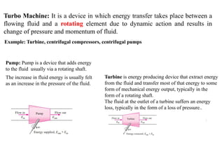
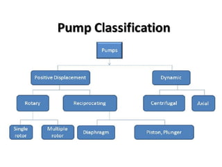
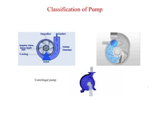
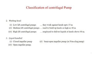
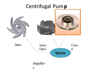
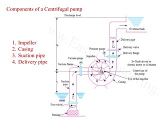
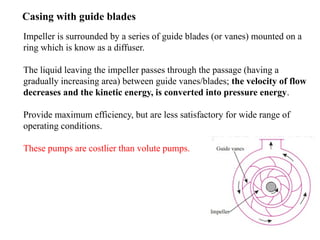
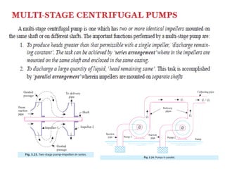
1
Turbo Machine: It is a device in which energy transfer takes place between a
flowing fluid and a rotating element due to dynamic action and results in
change of pressure and momentum of fluid.
10/31/2024
Example: Turbine, centrifugal compressors, centrifugal pumps
Pump: Pump is a device that adds energy
to the fluid usually via a rotating shaft.
The increase in fluid energy is usually felt
as an increase in the pressure of the fluid.
Turbine is energy producing device that extract energy
from the fluid and transfer most of that energy to some
form of mechanical energy output, typically in the
form of a rotating shaft.
The fluid at the outlet of a turbine suffers an energy
loss, typically in the form of a loss of pressure..
3
Classification of Pump
Gear pump Screw pump
Piston pump
Screw pump
Piston pump
4
Classification of Pump
Centrifugal pump
5
Advantages of Centrifugal pump over reciprocating pump
Centrifug
al How do they work?
• Liquid forced into
impeller
• Vanes pass kinetic
energy to liquid:
liquid rotates and
leaves impeller
• Volute casing
converts kinetic
energy into pressure
energy
7
Classification of centrifugal Pump
On the basis of characteristic features the centrifugal pumps can be classified as follows
8
Classification of centrifugal Pump
9
Classification of centrifugal Pump
5. Number of entrances to the impeller
i. Single entry or single suction pump Water is admitted on one side of the impeller
ii. Double entry or double suction pump Water is admitted from both sides of the
impeller: axial thrust is neutralized.
Employed for pumping large quantities of fluid.
10
Classification of centrifugal Pump
6. Relative direction of flow through impeller
i. Radial flow pump (Centrifugal pump)
ii. Axial flow pump (High discharge, low head, suitable for irrigation purpose)
iii. Mixed flow pump (Suited for irrigation purpose)
Open
Centrifugal Pum
Semi-
Open
Impeller
s
Close
d
Total
Head
H m
Centrifugal Pu Characteristic
Theoretical
Actual Discharge
Characteristic
13
Components of a Centrifugal pump
1. Impeller
2. Casing
3. Suction pipe
4. Delivery pipe
14
1. Impeller
An impeller is a wheel (or rotor) with a series of backward curved vanes (or
blades). It is mounted on a shaft which is usually coupled to an electric
motor.
The impellers are of following three types:
i. Shrouded or closed impeller
ii. Semi open impeller
iii. Open impeller
15
i. Shrouded or closed
impeller
ii. Semi open impeller
iii. Open impeller
 Vanes are provided with metal cover
plates or shrouds on both the sides
 Provides better guidance for the liquid
and has a high efficiency.
 Employed for pure and relatively
debris free liquid
 Vanes have only the base plate and no crown plate
 Suitable for liquid having some debris
 Vanes are open on both sides
 Suitable for liquid containing suspended solid matters
16
2. Casing
Types of Casing
It is an airtight chamber surrounding the impeller.
The essential purposes of the casing are
i. To guide water to and from the impeller
ii. To partially convert the kinetic energy into pressure energy
Volute Casing
Area of flow gradually increases from
the impeller outlet to the delivery
pipe. The increase in area of flow
decreases the velocity of flow.
Decrease in velocity increases
pressure of water flowing through the
casing.
The volute casing pump is the most
common type of centrifugal pump.
17
Vortex casing
A circular chamber known as vortex chamber is provided between the impeller
and the volute chamber.
The vortex chamber converts some of the kinetic energy into the pressure
energy.
The volute chamber further increases the pressure energy.
Thus the efficiency of a volute pump fitted with a vortex chamber is more than
that of a simple volute pump.
18
Casing with guide blades
Impeller is surrounded by a series of guide blades (or vanes) mounted on a
ring which is know as a diffuser.
The liquid leaving the impeller passes through the passage (having a
gradually increasing area) between guide vanes/blades; the velocity of flow
decreases and the kinetic energy, is converted into pressure energy.
Provide maximum efficiency, but are less satisfactory for wide range of
operating conditions.
These pumps are costlier than volute pumps.
19
Suction pipe
The pipe which connects the center/eye of the impeller to sump from
which liquid is to be lifted is known as suction pipe.
To prevent the entry of solid particles, debris etc. into the pump the
suction pipe is provided with a strainer at its lower end.
The lower end of the pipe is also fitted with a non-return foot valve
which does not permit the liquid to drain out of the suction pipe
when pump is not working; this also helps in priming.
20
Delivery pipe
The pipe which is connected at its lower end to the outlet of the pump
and it delivers the liquid to the required height is known as delivery
pipe.
A regulating valve is provided on the delivery pipe to regulate the
supply of water.
21
i. Where it is required to pump clear and fresh water, the impeller
is cast as a single piece and is made of castiron. The cast–iron
impellers are cheaper.
ii. Where corrosion due to salt water or chemicals is expected the
impellers are made of materials such as gunmetal, stainless steel
etc
iii. Machines (pumps) that handle hot water, having temperatures
above 150°C have to be made of cast steel impellers with special
types of packings.
iv. Where acids are to pumped, the impeller and all inside surfaces in
contact with liquid should be coated with a suitable material to
withstand corrosion.
v. Machines (pumps) employed in milk industry are made of
stainless steel to prevent con- tamination of the liquids handled.
Guidelines of impeller selection
22
A centrifugal pump works on the principle that when a certain mass
of fluid is rotated by an external source, it is thrown away from the
central axis of rotation and a centrifugal head is impressed which
enables it to rise to a higher level.
The working /operation of a centrifugal pump is explained step-
wise below:
i. The delivery valve is closed and the pump is primed that is,
suction pipe, casing and portion of the delivery pipe upto the
delivery valve are completely filled with the liquid (to be
pumped) so that no air pocket is left.
ii. Keeping the delivery valve still closed the electric motor is
started to rotate the impeller. The rotation of the impeller causes
strong suction or vaccum just at the eye of the casing
WORKING OF A CENTRIFUGAL PUMP
23
iii. The speed of the impeller is gradually increased till the
impeller rotates at its normal speed and develops normal
energy required for pumping the liquid.
iv. After the impeller attains the normal speed the delivery
valve is opened when the liquid is continuously sucked up
the suction pipe, it passes through the eye of casing and
enters the impeller at its centre or it enters the impeller vanes
at their inlet tips. This liquid is impelled out by the rotating
vanes and it comes out at the outlet tips of the vanes into the
casing. Due to impeller action the pressure head as well as
velocity heads of the liquid are increased (some of this
velocity heads is converted into pressure head in the casing
and in the diffuser blades/vanes if they are also provided).
WORKING OF A CENTRIFUGAL PUMP
24
v. From casing, the liquid passes into pipe and is lifted to the
required height (and discharged from the outlet or upper end
of the delivery pipe).
vi. So long as motion is given to the impeller and there is supply
of liquid to be lifted the process of lifting the liquid to the
required height remains continuous
vii.When pump is to be stopped the delivery valve should be
first closed, otherwise there may be some backflow from the
reservoir.
WORKING OF A CENTRIFUGAL PUMP
(i) Liquid enters the impeller eye in radial direction
(ii) No energy loss in the impeller due to friction and eddy formation.
(iii) No loss due to shock at entry.
(iv) There is uniform velocity distribution in the narrow passages
formed between two adjacent vanes.
WORK DONE BY THE IMPELLER (OR CENTRIFUGAL PUMP)
ON LIQUID
26
WORK DONE BY THE IMPELLER (OR CENTRIFUGAL PUMP) ON LIQUID
27
WORK DONE BY THE IMPELLER (OR CENTRIFUGAL PUMP) ON LIQUID
28
WORK DONE BY THE IMPELLER (OR CENTRIFUGAL PUMP) ON LIQUID
30
WORK DONE BY THE IMPELLER (OR CENTRIFUGAL PUMP) ON LIQUID
31
32
33
34
36
Net Positive Suction
Head
The has a PSN requirement in order to prevent
cavitation damage occurring and causing severe
damage.
A net positive suction head (NPSH) for a pump is the
difference between the liquid pressure at the pump’s
suction and the vapor pressure of the fluid being
pumped. It is the amount of energy available to exert
pressure on the fluid and is expressed in terms of
height of a liquid column i.e. in feet (not in pressure
gauge reading).
Cavitation
Cavitation occurs in centrifugal pumps when the Net Positive
Suction Head Available is lower than the Net Positive Suction
Head Required causing the formation and accumulation of
bubbles around the impeller eye that then collapse resulting in a
series of mini implosions and significant damage to both the
impeller and the casing.
If your pump sounds as though it is pumping marbles, then you
probably have a cavitation problem (or marbles have got into your
system). Other problems associated with cavitation are excessive
vibration that will lead to premature failure of seals and bearings,
higher power consumption, and decreased flow and pressure.
How To Prevent Pump Cavitation
Firstly, you need to identify the cause of the pressure drop. In most
cases, the problem can be solved by:
• Simplifying the suction pipework removing as many bends and
valves as possible
• Moving the pump closer to the fluid source
• Clean pipework and remove any blockage
• Increasing the diameter of the suction pipework so reducing the
inlet velocity
Centrifugal                    Pump.pptx

Centrifugal Pump.pptx

  • 1.
    1 Turbo Machine: Itis a device in which energy transfer takes place between a flowing fluid and a rotating element due to dynamic action and results in change of pressure and momentum of fluid. 10/31/2024 Example: Turbine, centrifugal compressors, centrifugal pumps Pump: Pump is a device that adds energy to the fluid usually via a rotating shaft. The increase in fluid energy is usually felt as an increase in the pressure of the fluid. Turbine is energy producing device that extract energy from the fluid and transfer most of that energy to some form of mechanical energy output, typically in the form of a rotating shaft. The fluid at the outlet of a turbine suffers an energy loss, typically in the form of a loss of pressure..
  • 3.
    3 Classification of Pump Gearpump Screw pump Piston pump Screw pump Piston pump
  • 4.
  • 5.
    5 Advantages of Centrifugalpump over reciprocating pump
  • 6.
    Centrifug al How dothey work? • Liquid forced into impeller • Vanes pass kinetic energy to liquid: liquid rotates and leaves impeller • Volute casing converts kinetic energy into pressure energy
  • 7.
    7 Classification of centrifugalPump On the basis of characteristic features the centrifugal pumps can be classified as follows
  • 8.
  • 9.
    9 Classification of centrifugalPump 5. Number of entrances to the impeller i. Single entry or single suction pump Water is admitted on one side of the impeller ii. Double entry or double suction pump Water is admitted from both sides of the impeller: axial thrust is neutralized. Employed for pumping large quantities of fluid.
  • 10.
    10 Classification of centrifugalPump 6. Relative direction of flow through impeller i. Radial flow pump (Centrifugal pump) ii. Axial flow pump (High discharge, low head, suitable for irrigation purpose) iii. Mixed flow pump (Suited for irrigation purpose)
  • 11.
  • 12.
    Total Head H m Centrifugal PuCharacteristic Theoretical Actual Discharge Characteristic
  • 13.
    13 Components of aCentrifugal pump 1. Impeller 2. Casing 3. Suction pipe 4. Delivery pipe
  • 14.
    14 1. Impeller An impelleris a wheel (or rotor) with a series of backward curved vanes (or blades). It is mounted on a shaft which is usually coupled to an electric motor. The impellers are of following three types: i. Shrouded or closed impeller ii. Semi open impeller iii. Open impeller
  • 15.
    15 i. Shrouded orclosed impeller ii. Semi open impeller iii. Open impeller  Vanes are provided with metal cover plates or shrouds on both the sides  Provides better guidance for the liquid and has a high efficiency.  Employed for pure and relatively debris free liquid  Vanes have only the base plate and no crown plate  Suitable for liquid having some debris  Vanes are open on both sides  Suitable for liquid containing suspended solid matters
  • 16.
    16 2. Casing Types ofCasing It is an airtight chamber surrounding the impeller. The essential purposes of the casing are i. To guide water to and from the impeller ii. To partially convert the kinetic energy into pressure energy Volute Casing Area of flow gradually increases from the impeller outlet to the delivery pipe. The increase in area of flow decreases the velocity of flow. Decrease in velocity increases pressure of water flowing through the casing. The volute casing pump is the most common type of centrifugal pump.
  • 17.
    17 Vortex casing A circularchamber known as vortex chamber is provided between the impeller and the volute chamber. The vortex chamber converts some of the kinetic energy into the pressure energy. The volute chamber further increases the pressure energy. Thus the efficiency of a volute pump fitted with a vortex chamber is more than that of a simple volute pump.
  • 18.
    18 Casing with guideblades Impeller is surrounded by a series of guide blades (or vanes) mounted on a ring which is know as a diffuser. The liquid leaving the impeller passes through the passage (having a gradually increasing area) between guide vanes/blades; the velocity of flow decreases and the kinetic energy, is converted into pressure energy. Provide maximum efficiency, but are less satisfactory for wide range of operating conditions. These pumps are costlier than volute pumps.
  • 19.
    19 Suction pipe The pipewhich connects the center/eye of the impeller to sump from which liquid is to be lifted is known as suction pipe. To prevent the entry of solid particles, debris etc. into the pump the suction pipe is provided with a strainer at its lower end. The lower end of the pipe is also fitted with a non-return foot valve which does not permit the liquid to drain out of the suction pipe when pump is not working; this also helps in priming.
  • 20.
    20 Delivery pipe The pipewhich is connected at its lower end to the outlet of the pump and it delivers the liquid to the required height is known as delivery pipe. A regulating valve is provided on the delivery pipe to regulate the supply of water.
  • 21.
    21 i. Where itis required to pump clear and fresh water, the impeller is cast as a single piece and is made of castiron. The cast–iron impellers are cheaper. ii. Where corrosion due to salt water or chemicals is expected the impellers are made of materials such as gunmetal, stainless steel etc iii. Machines (pumps) that handle hot water, having temperatures above 150°C have to be made of cast steel impellers with special types of packings. iv. Where acids are to pumped, the impeller and all inside surfaces in contact with liquid should be coated with a suitable material to withstand corrosion. v. Machines (pumps) employed in milk industry are made of stainless steel to prevent con- tamination of the liquids handled. Guidelines of impeller selection
  • 22.
    22 A centrifugal pumpworks on the principle that when a certain mass of fluid is rotated by an external source, it is thrown away from the central axis of rotation and a centrifugal head is impressed which enables it to rise to a higher level. The working /operation of a centrifugal pump is explained step- wise below: i. The delivery valve is closed and the pump is primed that is, suction pipe, casing and portion of the delivery pipe upto the delivery valve are completely filled with the liquid (to be pumped) so that no air pocket is left. ii. Keeping the delivery valve still closed the electric motor is started to rotate the impeller. The rotation of the impeller causes strong suction or vaccum just at the eye of the casing WORKING OF A CENTRIFUGAL PUMP
  • 23.
    23 iii. The speedof the impeller is gradually increased till the impeller rotates at its normal speed and develops normal energy required for pumping the liquid. iv. After the impeller attains the normal speed the delivery valve is opened when the liquid is continuously sucked up the suction pipe, it passes through the eye of casing and enters the impeller at its centre or it enters the impeller vanes at their inlet tips. This liquid is impelled out by the rotating vanes and it comes out at the outlet tips of the vanes into the casing. Due to impeller action the pressure head as well as velocity heads of the liquid are increased (some of this velocity heads is converted into pressure head in the casing and in the diffuser blades/vanes if they are also provided). WORKING OF A CENTRIFUGAL PUMP
  • 24.
    24 v. From casing,the liquid passes into pipe and is lifted to the required height (and discharged from the outlet or upper end of the delivery pipe). vi. So long as motion is given to the impeller and there is supply of liquid to be lifted the process of lifting the liquid to the required height remains continuous vii.When pump is to be stopped the delivery valve should be first closed, otherwise there may be some backflow from the reservoir. WORKING OF A CENTRIFUGAL PUMP
  • 25.
    (i) Liquid entersthe impeller eye in radial direction (ii) No energy loss in the impeller due to friction and eddy formation. (iii) No loss due to shock at entry. (iv) There is uniform velocity distribution in the narrow passages formed between two adjacent vanes. WORK DONE BY THE IMPELLER (OR CENTRIFUGAL PUMP) ON LIQUID
  • 26.
    26 WORK DONE BYTHE IMPELLER (OR CENTRIFUGAL PUMP) ON LIQUID
  • 27.
    27 WORK DONE BYTHE IMPELLER (OR CENTRIFUGAL PUMP) ON LIQUID
  • 28.
    28 WORK DONE BYTHE IMPELLER (OR CENTRIFUGAL PUMP) ON LIQUID
  • 29.
    WORK DONE BYTHE IMPELLER (OR CENTRIFUGAL PUMP) ON LIQUID
  • 30.
    30 WORK DONE BYTHE IMPELLER (OR CENTRIFUGAL PUMP) ON LIQUID
  • 31.
  • 32.
  • 33.
  • 34.
  • 36.
  • 42.
    Net Positive Suction Head Thehas a PSN requirement in order to prevent cavitation damage occurring and causing severe damage. A net positive suction head (NPSH) for a pump is the difference between the liquid pressure at the pump’s suction and the vapor pressure of the fluid being pumped. It is the amount of energy available to exert pressure on the fluid and is expressed in terms of height of a liquid column i.e. in feet (not in pressure gauge reading).
  • 43.
    Cavitation Cavitation occurs incentrifugal pumps when the Net Positive Suction Head Available is lower than the Net Positive Suction Head Required causing the formation and accumulation of bubbles around the impeller eye that then collapse resulting in a series of mini implosions and significant damage to both the impeller and the casing. If your pump sounds as though it is pumping marbles, then you probably have a cavitation problem (or marbles have got into your system). Other problems associated with cavitation are excessive vibration that will lead to premature failure of seals and bearings, higher power consumption, and decreased flow and pressure.
  • 44.
    How To PreventPump Cavitation Firstly, you need to identify the cause of the pressure drop. In most cases, the problem can be solved by: • Simplifying the suction pipework removing as many bends and valves as possible • Moving the pump closer to the fluid source • Clean pipework and remove any blockage • Increasing the diameter of the suction pipework so reducing the inlet velocity