Carry-save addition allows three n-bit numbers to be added together in O(1) time by computing the sum and carry independently and in parallel. It works by using a carry-save adder (CSA) block for each bit position. A CSA block takes in three bits and outputs their sum and carry without propagating the carry. Multiple CSA blocks can be chained or arranged in a Wallace tree to add many numbers. Using a chain takes O(m + lg(n+m)) time while a Wallace tree takes O(logm + lg(n+logm)) time to add m n-bit numbers.
In this document
Powered by AI
Introduction to carry-save addition, adding multiple numbers, and the efficiency in O(1) time for computing sum and carry.
Explanation of carry save adder as a full adder, its arrangement for n-bit numbers, and the efficiency achieved, including necessary LCA delay.
Description of the Wallace tree structure for adding m n-bit numbers, depths, and gate delays involved in the process.
Visual representation of a Wallace tree for adding m n-bit numbers to illustrate the efficient organization of CSAs.
Carry-Save Addition
Prof. Loh
CS3220- Processor Design - Spring 2005
February 2, 2005
1 Adding Multiple Numbers
There are many cases where it is desired to add more than two numbers together. The straightforward way of adding
together m numbers (all n bits wide) is to add the first two, then add that sum to the next, and so on. This requires
a total of m − 1 additions, for a total gate delay of O(m lg n) (assuming lookahead carry adders). Instead, a tree of
adders can be formed, taking only O(lg m · lg n) gate delays.
Using carry save addition, the delay can be reduced further still. The idea is to take 3 numbers that we want to add
together, x + y + z, and convert it into 2 numbers c + s such that x + y + z = c + s, and do this in O(1) time. The
reason why addition can not be performed in O(1) time is because the carry information must be propagated. In carry
save addition, we refrain from directly passing on the carry information until the very last step. We will first illustrate
the general concept with a base 10 example.
To add three numbers by hand, we typically align the three operands, and then proceed column by column in the
same fashion that we perform addition with two numbers. The three digits in a row are added, and any overflow goes
into the next column. Observe that when there is some non-zero carry, we are really adding four digits (the digits of
x,y and z, plus the carry).
carry: 1 1 2 1
x: 1 2 3 4 5
y: 3 8 1 7 2
z: + 2 0 5 8 7
sum: 7 1 1 0 4
The carry save approach breaks this process down into two steps. The first is to compute the sum ignoring any carries:
x: 1 2 3 4 5
y: 3 8 1 7 2
z: + 2 0 5 8 7
s: 6 0 9 9 4
Each si is equal to the sum of xi + yi + zi modulo 10. Now, separately, we can compute the carry on a column by
column basis:
x: 1 2 3 4 5
y: 3 8 1 7 2
z: + 2 0 5 8 7
c: 1 0 1 1
In this case, each ci is the sum of the bits from the previous column divided by 10 (ignoring any remainder). Another
way to look at it is that any carry over from one column gets put into the next column. Now, we can add together c
and s, and we’ll verify that it indeed is equal to x + y + z:
1
2.
x y
cincout
s
⇒
c s
xy z
FA CSA
Figure 1: The carry save adder block is the same circuit as the full adder.
x0 y0 z0
s0c1
CSA
x1 y1 z1
s1c2
CSA
x2 y2 z2
s2c3
CSA
x3 y3 z3
s3c4
CSA
x4 y4 z4
s4c5
CSA
x5 y5 z5
s5c6
CSA
x6 y6 z6
s6c7
CSA
x7 y7 z7
s7c8
CSA
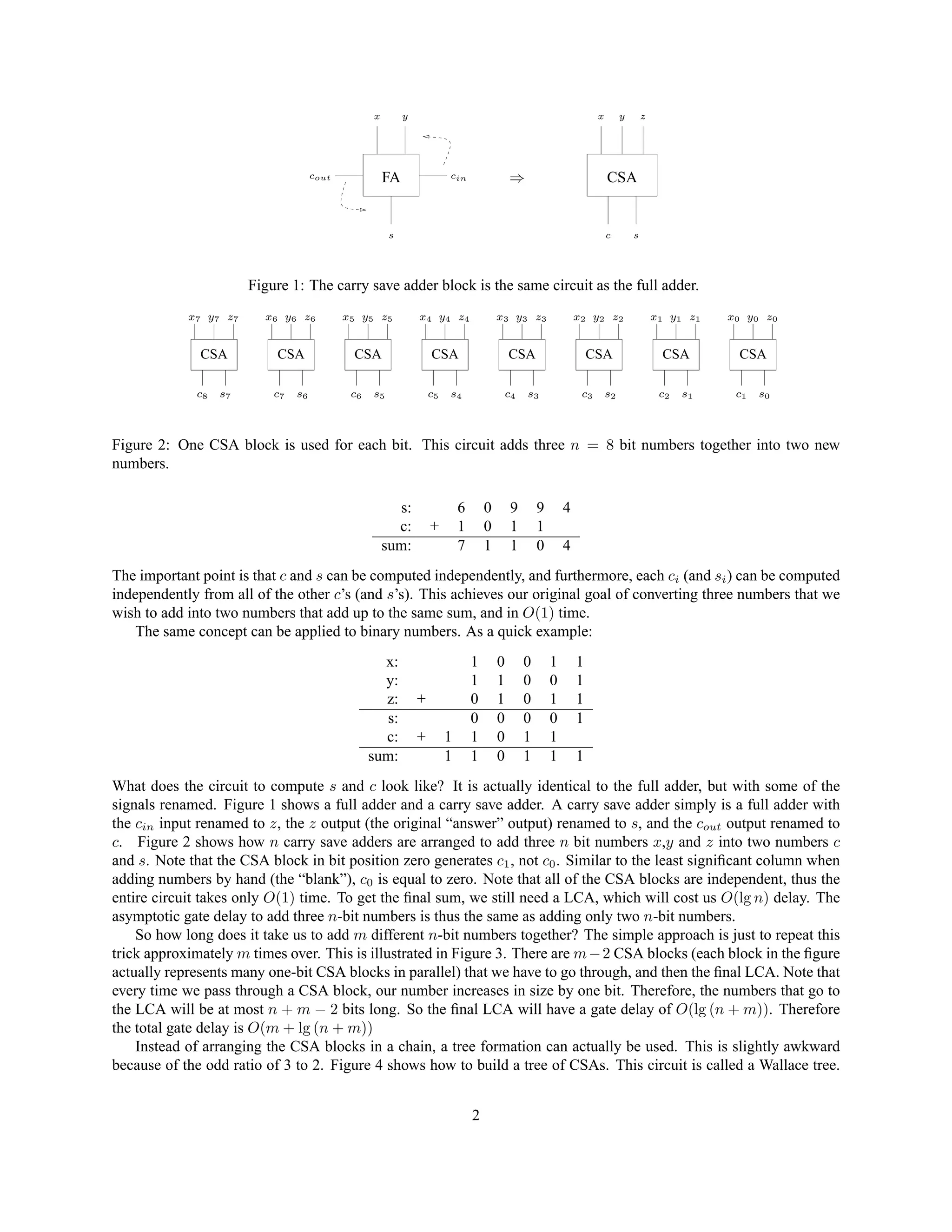
Figure 2: One CSA block is used for each bit. This circuit adds three n = 8 bit numbers together into two new
numbers.
s: 6 0 9 9 4
c: + 1 0 1 1
sum: 7 1 1 0 4
The important point is that c and s can be computed independently, and furthermore, each ci (and si) can be computed
independently from all of the other c’s (and s’s). This achieves our original goal of converting three numbers that we
wish to add into two numbers that add up to the same sum, and in O(1) time.
The same concept can be applied to binary numbers. As a quick example:
x: 1 0 0 1 1
y: 1 1 0 0 1
z: + 0 1 0 1 1
s: 0 0 0 0 1
c: + 1 1 0 1 1
sum: 1 1 0 1 1 1
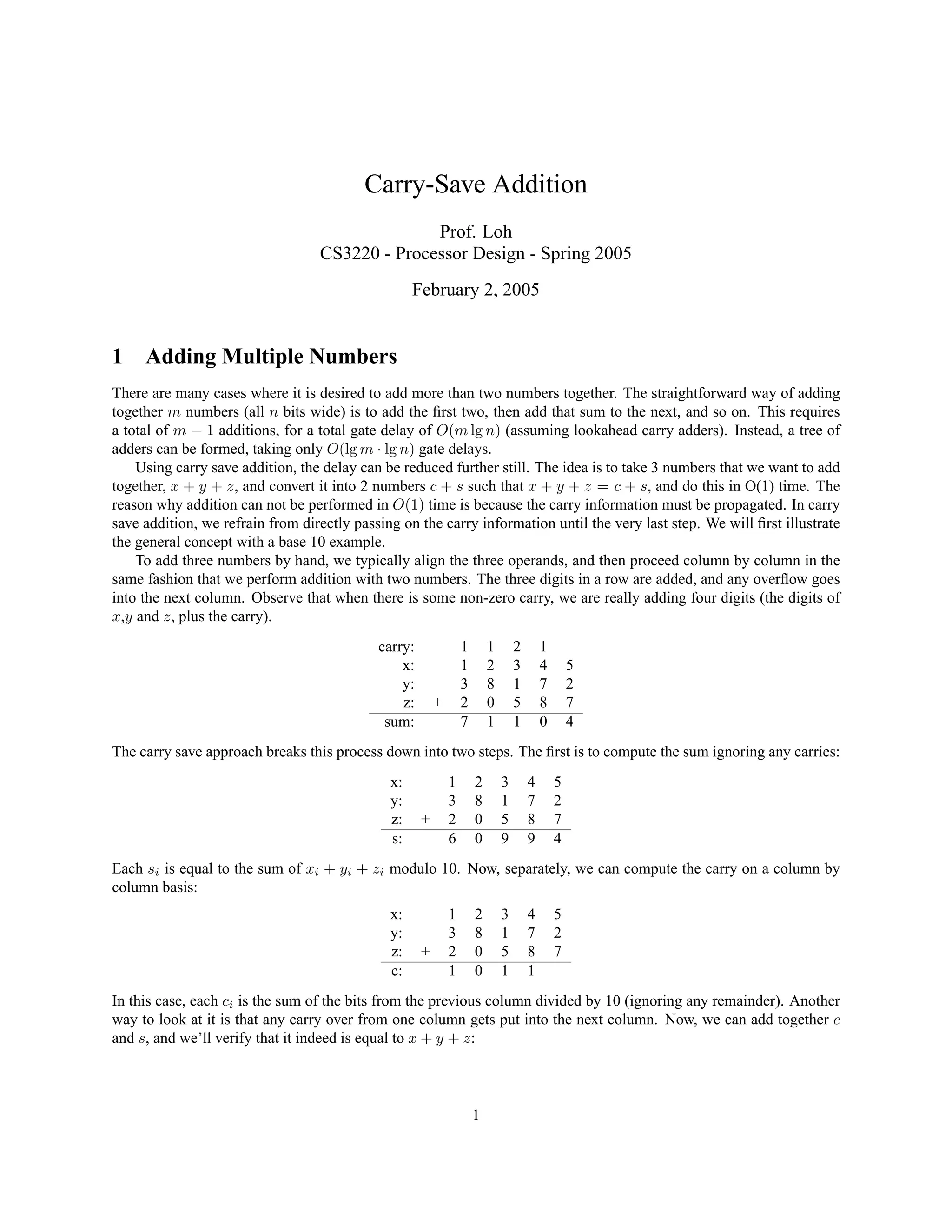
What does the circuit to compute s and c look like? It is actually identical to the full adder, but with some of the
signals renamed. Figure 1 shows a full adder and a carry save adder. A carry save adder simply is a full adder with
the cin input renamed to z, the z output (the original “answer” output) renamed to s, and the cout output renamed to
c. Figure 2 shows how n carry save adders are arranged to add three n bit numbers x,y and z into two numbers c
and s. Note that the CSA block in bit position zero generates c1, not c0. Similar to the least significant column when
adding numbers by hand (the “blank”), c0 is equal to zero. Note that all of the CSA blocks are independent, thus the
entire circuit takes only O(1) time. To get the final sum, we still need a LCA, which will cost us O(lg n) delay. The
asymptotic gate delay to add three n-bit numbers is thus the same as adding only two n-bit numbers.
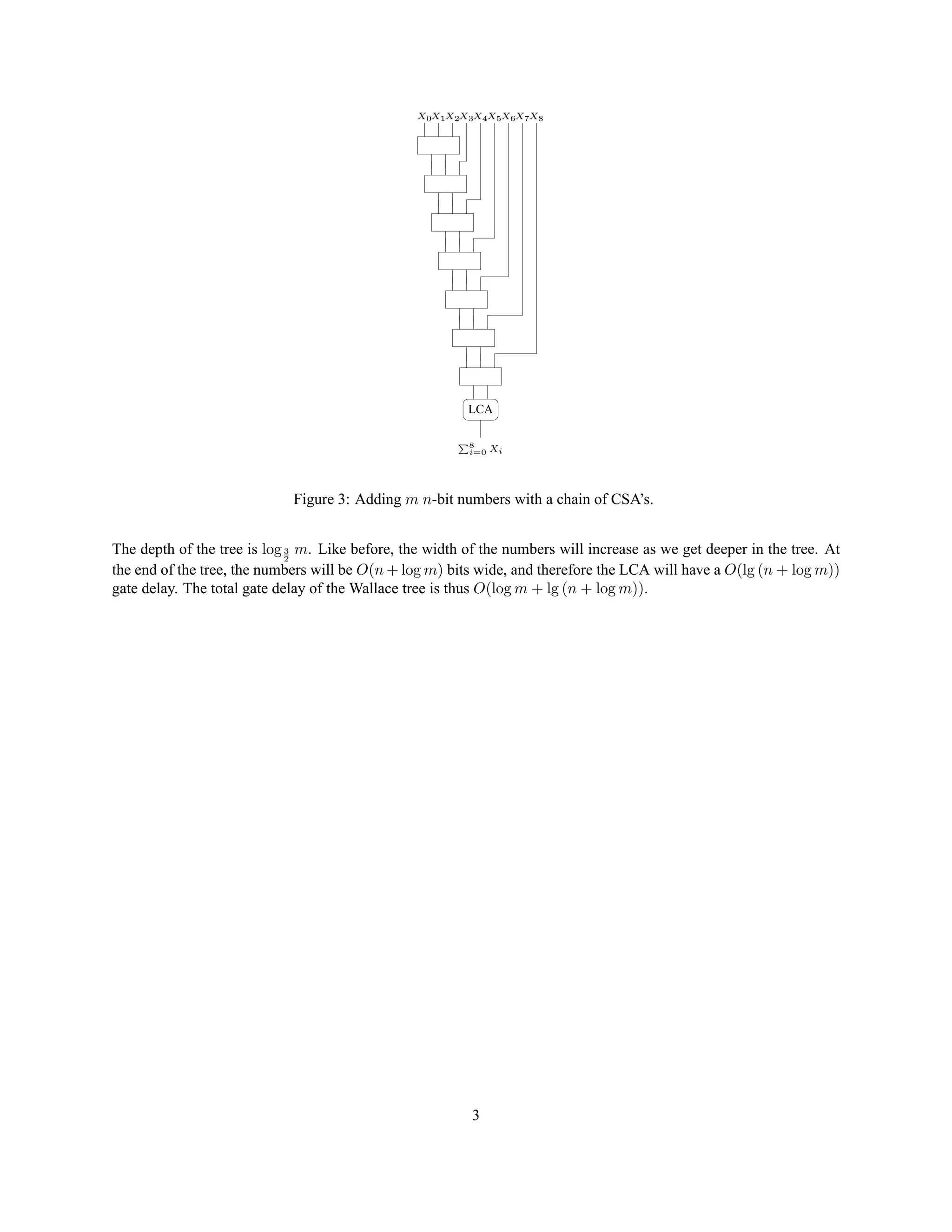
So how long does it take us to add m different n-bit numbers together? The simple approach is just to repeat this
trick approximately m times over. This is illustrated in Figure 3. There are m−2 CSA blocks (each block in the figure
actually represents many one-bit CSA blocks in parallel) that we have to go through, and then the final LCA. Note that
every time we pass through a CSA block, our number increases in size by one bit. Therefore, the numbers that go to
the LCA will be at most n + m − 2 bits long. So the final LCA will have a gate delay of O(lg (n + m)). Therefore
the total gate delay is O(m + lg (n + m))
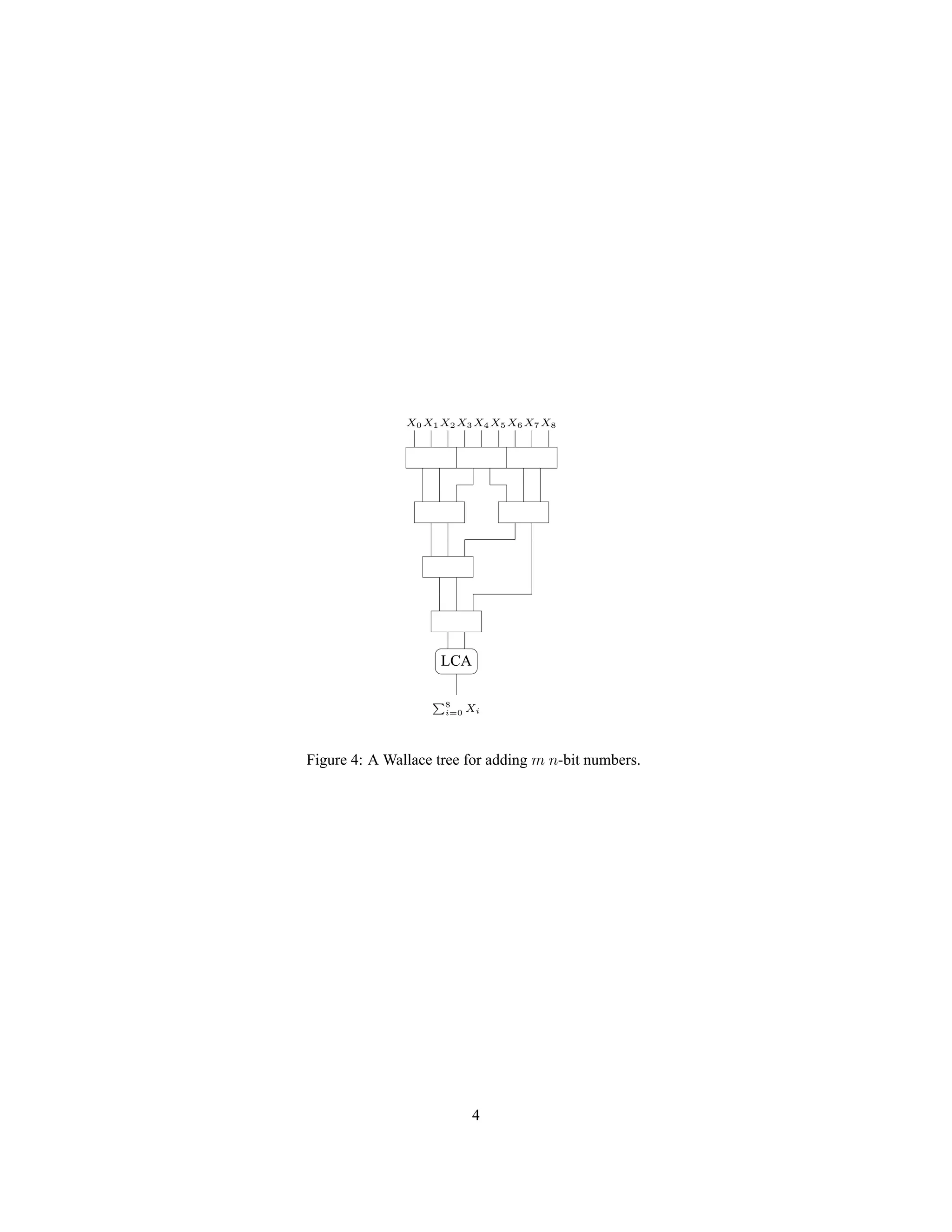
Instead of arranging the CSA blocks in a chain, a tree formation can actually be used. This is slightly awkward
because of the odd ratio of 3 to 2. Figure 4 shows how to build a tree of CSAs. This circuit is called a Wallace tree.
2
3.
X0X1X2X3X4X5X6X7X8
LCA
P8
i=0 Xi
Figure 3:Adding m n-bit numbers with a chain of CSA’s.
The depth of the tree is log3
2
m. Like before, the width of the numbers will increase as we get deeper in the tree. At
the end of the tree, the numbers will be O(n + log m) bits wide, and therefore the LCA will have a O(lg (n + log m))
gate delay. The total gate delay of the Wallace tree is thus O(log m + lg (n + log m)).
3
4.
LCA
P8
i=0 Xi
X0 X1X2 X3 X4 X5 X6 X7 X8
Figure 4: A Wallace tree for adding m n-bit numbers.
4