
![Cargo securing manual
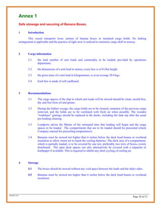
Introduction
1 The information contained in this Cargo Securing Manual, required in accordance with the 1994 amendments
to the International Convention for the Safety of Life at Sea, 1974 (SOLAS) VI/5.6 and VII/6.6, is in an
approved form in accordance with the Guidelines for the Preparation of the Cargo Securing Manual,
MSC/Circ.745.
2 The purpose of this manual is to provide guidance to the Master and crew on board the vessel with respect to
the proper stowage and securing of cargo units.
3 It is the Masters responsibility to ensure that cargo units (as defined in MSC/Circ.745) are at all times stowed
and secured in an efficient manner, taking into account the prevailing conditions and the general principals of
safe stowage set out in this Manual, and that the securing equipment and timber used are adequate for the
loadings calculated in accordance with this Manual.
4 This Manual should be kept on board the vessel for inspection by Port/Flag State inspectors, Classification
Society Surveyors and other interested parties.
5 This manual has been approved by Lloyd’s Register of Shipping on behalf of the Government of
Republic of MALTA .
6 The information contained in or appended to this manual should be regularly reviewed and updated. With the
exception of the lists of portable cargo securing devices where equipment is replaced with new equipment of an
identical type, amendments should not be made to this Manual without the prior consent of Lloyd’s Register of
Shipping.
Scope of this Manual
M.V. Tropical Estoril is a Reefer Cargo vessel designed for carriage of break-bulk refrigerated Cargo. The vessel is
owned and operated by [An existing Reefer Company] (and/or subsidiaries). The Vessel carries reefer fruit cargo in
loose boxes. This Manual will discuss loading and securing practices as applicable to such cargo.
It is to be noted that this vessel is not designed for unitised pallet loads (the cargo spaces vary in height and width and
are not provided with side shoring arrangements).
Further, the vessel does not comply with requirements for carriage of dangerous goods and is not designed or adapted
for carriage of freight containers or other mobile transport units.
Nothing in this manual should be read to exclude the use of computer software or other aids, provided the output
achieves minimum safety factors/parameters.
PKOHLI-TES
Page 3 of 31](https://image.slidesharecdn.com/csm-tes-1232824167796630-3/85/Cargo-Securing-Manual-3-320.jpg)

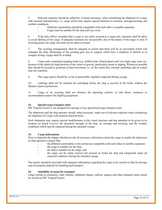

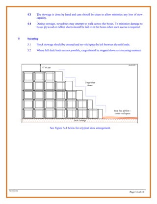
![5. Advanced calculation method
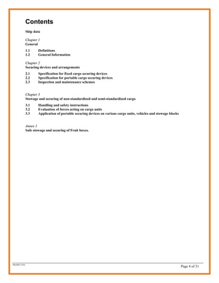
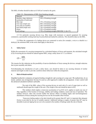
In the advanced method, acceleration is applied to cargo mass to obtain the external forces to a cargo unit in
longitudinal, transverse and vertical directions. This calculation then enables us to compare with the securing
force which is applied to this cargo through application of lashing.
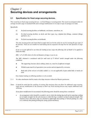
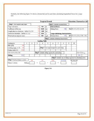
The acceleration data for Tropical Estoril are presented in the tables 3-1 and 3-2.
Table 3-1
Vessel Name: Tropical Estoril Ship IMO No: 738073
Accelerations according to Annex 13 to IMO Res. A714(17)
2
Transverse acceleration ay in m/s Long acc
Long. position: 0.0 0.1 0.2 0.3 0.4 0.5 0.6 0.7 0.8 0.9 1.0 ax in m/s2
Deck, high 6.68 6.68 6.49 6.40 6.30 6.30 6.40 6.49 6.68 6.96 6.96 3.57
Deck, low 6.11 6.11 5.92 5.74 5.74 5.74 5.74 5.92 6.11 6.30 6.30 2.73
Tween-deck 5.55 5.55 5.27 5.17 5.08 5.08 5.17 5.27 5.55 5.83 5.83 1.88
Lower hold 5.17 5.17 4.98 4.80 4.70 4.70 4.80 4.98 5.17 5.55 5.55 1.41
2
Vertical acceleration az in m/s
7.15 7.15 5.83 4.70 4.04 4.04 4.70 5.83 7.15 8.65 8.65
Note !
Accelerations according to IMO Res.A714(17), Annex 13.
Accelerations 10.00
Vert. accel., az
apply for GM of
0.15m to 1.25m 9.00
Deck high, ay
8.00
Deck low, ay
7.00
Acceleration, [m/s2]
Tween deck, ay
6.00
Lower hold, ay
5.00
4.00 Deck high, ax
3.00 Deck low, ax
2.00 Tween deck, ax
1.00
Lower hold, ax
0.00
0.0 0.1 0.2 0.3 0.4 0.5 0.6 0.7 0.8 0.9 1.0
Longitudinal position, x/L
pkohli-dffi
Above table 3-1 shows accelerations as evident on MV Tropical Estoril over a range of GM values from 0.15 to 1.25m.
No change in acceleration is quantifiable over this GM range.
PKOHLI-TES
Page 19 of 31](https://image.slidesharecdn.com/csm-tes-1232824167796630-3/85/Cargo-Securing-Manual-19-320.jpg)
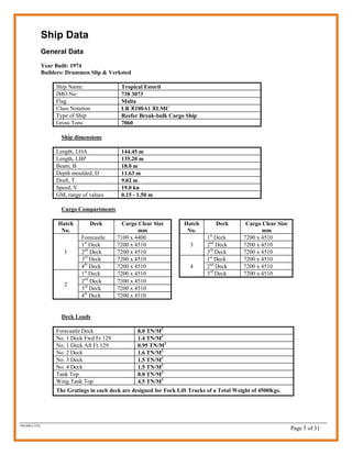
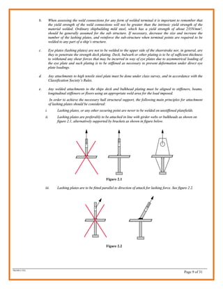
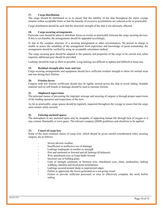
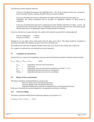
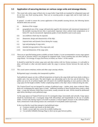
![Table 3-2
Vessel Name: Tropical Estoril Ship IMO No: 738073
Accelerations according to Annex 13 to IMO Res. A714(17)
Transverse acceleration ay in m/s2 Long acc
Long. position: 0.0 0.1 0.2 0.3 0.4 0.5 0.6 0.7 0.8 0.9 1.0 ax in m/s2
Deck, high 7.01 7.01 6.81 6.71 6.62 6.62 6.71 6.81 7.01 7.31 7.31 3.57
Deck, low 6.36 6.36 6.16 5.97 5.97 5.97 5.97 6.16 6.36 6.55 6.55 2.73
Tween-deck 5.72 5.72 5.42 5.33 5.23 5.23 5.33 5.42 5.72 6.01 6.01 1.88
Lower hold 5.28 5.28 5.08 4.89 4.80 4.80 4.89 5.08 5.28 5.66 5.66 1.41
Vertical acceleration az in m/s2
7.15 7.15 5.83 4.70 4.04 4.04 4.70 5.83 7.15 8.65 8.65
Note !
Accelerations according to IMO Res.A714(17), Annex 13.
Accelerations 10.00
Vert. accel., az
apply for GM of
1.50m 9.00
Deck high, ay
8.00
Deck low, ay
7.00
Acceleration, [m/s2]
Tween deck, ay
6.00
Lower hold, ay
5.00
4.00 Deck high, ax
3.00 Deck low, ax
2.00 Tween deck, ax
1.00
Lower hold, ax
0.00
0.0 0.1 0.2 0.3 0.4 0.5 0.6 0.7 0.8 0.9 1.0
Longitudinal position, x/L
pkohli-dffi
Above table 3-1 shows accelerations as evident on MV Tropical Estoril at a of GM value 1.50m.
Remarks:
The given transverse acceleration figures include components of gravity, pitch and heave parallel to the deck. The given
vertical acceleration figures do not include the static weight component.
The basic acceleration data are to be considered as valid under the following operational conditions:
1 Operation in unrestricted area;
2 Operation during the whole year;
3 Duration of the voyage is 25 days;
4 Length of ship is 135.2 m (for Tropical Estoril);
5 Service speed is 19.5 knots (for Tropical Estoril);
6 GM range of 0.15 to 1.25m and GM of 1.50m (for Tropical Estoril).
PKOHLI-TES
Page 20 of 31](https://image.slidesharecdn.com/csm-tes-1232824167796630-3/85/Cargo-Securing-Manual-20-320.jpg)


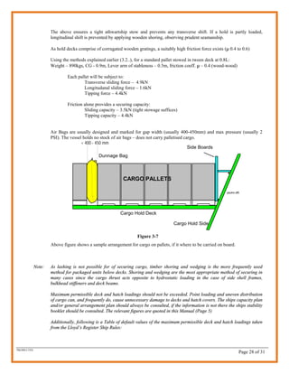


This cargo securing manual provides guidelines for securing cargo on board the MV Tropical Estoril. [1] It describes the vessel as having no fixed cargo securing devices and being designed solely for carriage of refrigerated cargo in insulated holds. [2] Portable securing devices are not required for the banana boxes typically carried as individual unit loads with block stowage. [3] Any future modifications requiring additional securing points would need to ensure the ship's structure can withstand the added loads.


