
More Related Content
Similar to ut.pptx
Similar to ut.pptx (20)
More from DHARUNESHBOOPATHY
Recently uploaded
Recently uploaded (20)
ut.pptx
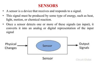
- 1. SENSORS • A sensor is a device that receives and responds to a signal. • This signal must be produced by some type of energy, such as heat, light, motion, or chemical reaction. • Once a sensor detects one or more of these signals (an input), it converts it into an analog or digital representation of the input signal
- 2. Transducer • A transducer is defined as a substance or a device that converts (or transfers) an input energy into a different output energy.
- 4. The Transducer can be classified I. On the basis of principle of transduction form used II. As primary and secondary transducer III. As passive and active transducer IV. As analog and digital transducer V. As transducers and inverse transducer On the basis of principle of transduction form used • The transducers can be classified based upon how they convert the input quantity into resistance, capacitance ,inductance. Resistive Transducer: Resistance of an electrical conductor is given by, R = ρl/A Where R = Resistance in Ω ρ = Resistivity of the conductor (Ω - cm) l = Length of the conductor in cm. A = Cross-sectional area of the metal conductor in cm2
- 5. It is clear from the equation that, the electrical resistance can be varied by varying (i) Length (ii) Cross-sectional area (iii) Resistivity or combination of these. The change in electrical resistance is caused by means of pressure, temperature, force, displacement. Eg : Potentiometer, Strain gauge, RTD, Thermistor. S NO Transducer Basic Principle (Variation of) Measurement 1 Potentiometer R due to movement of slider caused by external force Pressure Displacement 2 Resistance Strain Gauge R of a wire/semiconductor due to elongation /compression caused by externally applied stress Force Displacement 3 Resistance thermometer R of pure metal (having positive temperature co-efficient) with change of temperature Temperature 4 Thermistor R of pure metal oxide (having negative temperature co-efficient) with change of temperature Temperature
- 6. Inductive Transducer The inductive transducer works upon one of the following three principles: a) Change of self inductance b) Change of mutual inductance c) Production of eddy current Inductive transducer are mainly used for measurement of displacement. Eg : LVDT ,Variable Reluctance, Magnetostriction gauge S.No Transducer Basic Principle(Variation of) Measurement 1 Differential Transformer Differential Voltage of two secondary windings due to change in position of the core Displacement, Position, Pressure ,Force 2 Variable Reluctance Reluctance of magnetic circuit due to change in position of core or coil Position Force Pressure 3 Magnetostriction gauge Magnetic properties changes due to application of force or stress Force Sound Pressure
- 7. Capacitive Transducer • As Capacitance C is a function of ϵr , A, d (i.e) C = f (ϵr , A, d), when anyone of these quantities changes, the capacitance varies. This leads to the design of a variable capacitance transducer. • Eg : Capacitor microphone, dielectric gauge, Variable capacitance pressure gauge
- 8. Active and Passive Transducer Passive Transducer : These transducer derive the power required for transduction from an auxillary power source. They are also known as “externally powered transducer” Eg : Resistive ,Inductive and Capacitive transducer S .NO Transducer Basic Principle(Variation of) Measurement 1 Variable Capacitance Gauge C changes due to change of distance between two parallel plates caused by externally applied force Displacement Pressure 2 Capacitor Microphone C changes due to sound pressure on a movable diaphragm Sound Music Noise 3 Dielectric Gauge C due to change in dielectric Liquid Level Thickness
- 9. Active Transducer These transducer do not require an auxillary power source to produce their output. They are also known as self generating type since they develop their own voltage as output. The energy required for production of output signal is obtained from the physical quantity being measured. Eg : Piezoelectric crystal, thermocouple
- 10. VARIABLE AREA-BASED CAPACITIVE TRANSDUCER • The capacitance is directly proportional to the area of cross-section of the parallel plates. • The capacitance changes linearly with change in area of the plates. • Hence, the capacitive transducers based on the variable area are suited for the measurement of both linear and angular displacements. MEASUREMENT OF LINEAR DISPLACEMENT
- 11. • The linear displacement to be measured by the capacitive transducer is applied to the plate which is movable. • Now, there will be overlapping of the plates. • Due to this, there will be change in capacitance. • The amount of capacitance change is proportional to the displacement applied to the movable plate. • The above parallel plate capacitive transducer is suitable for linear displacement measurements in the range of 1 mm to 10 mm with an accuracy of 0.005% • The capacitance is directly proportional to the area of the plates and varies linearly with changes in the displacement between the plates. • Instead of a two parallel plate capacitive transducer, a cylindrical capacitive transducer can also be used for the measurement of linear displacement. • It consists of two cylindrical electrodes. • One cylindrical electrode is a fixed one, whereas the other cylindrical electrode is movable one
- 12. • Similar to the parallel plate capacitive transducer, the linear displacement to be measured is applied to the movable cylinder which results in overlapping of two cylinders which in turn further makes a change in capacitance between the two cylindrical electrodes. • The amount of capacitance is proportional to the displacement applied to the movable cylinder.
- 13. MEASUREMENT OF ANGULAR DISPLACEMENT • It consists of a set of semi-circular plates forming the two plates of the capacitor, out of which one plate is fixed and the other plate is movable. • The angular displacement to be measured is applied to the movable plate of the transducer assembly. • Hence there is a change in effective area between the semicircular plates which in turn changes the capacitance. • The amount of capacitance change is depending on the angular displacement applied to the movable plate, and it is observed that it is maximum when the plates overlap each other which means the angular displacement θ = 180 °.
- 14. • At various angular displacements of θ, the capacitance is determined by C =Ɛ θ r2 / d Where, r is the radius of semi-circular plates. 𝜃 is the angular displacement. D is the gap between two plates. VARIABLE DISTANCE-BASED CAPACITIVE TRANSDUCER • The capacitance is inversely proportional to the distance between the two plates of the capacitor . • With this principle, variable distance based capacitive transducer used for the measurement of linear displacements.
- 15. • Variable distance based capacitive transducer consists of two plates among which one plate is fixed, and the other one is movable. • The linear displacement to be measured is applied to the movable plate. • When the displacement is towards left, the distance between the plates decreases and hence the capacitance increases. Whereas when the displacement is towards right, the distance between the plates increases and hence the capacitance decreases.
- 16. • Since the capacitance is inversely proportional to the variation in distance between the plates, the response of the transducer is found to be non-linear. • Due to this nonlinearity in response, it is useful for the measurement of only smaller displacements.
- 17. VARIABLE DIELECTRIC-BASED CAPACITIVE TRANSDUCER • This kind of capacitive transducer works based on variation in the dielectric material and its corresponding dielectric constant. • This arrangement is suitable for large linear displacements. • Here, the two capacitor plates are kept in fixed position, whereas the solid dielectric material available between the fixed plates is movable thereby varying the capacitance of the transducer assembly. • The figure shows that how in a capacitor the position of the dielectric is varied to vary the capacitance
- 18. • If the area (A) of and the distance (d) between the plates of a capacitor remain constant, capacitance will vary only as a function of the dielectric constant (e) of the substance filling the gap between the plates. • If the space between the plates of a capacitor is filled with an insulator, the capacitance of the capacitor will change compared to the situation in which there is vacuum between the plates. • The change in the capacitance is caused by a change in the electric field between the plates. • Many factors will cause the dielectric constant (e) to change, and this change in dielectric constant (e) will vary for different materials. • The major factors that will cause a change in dielectric constant (e) are moisture, voltage, frequency, and temperature, moisture, humidity, material bulk density, and particle size etc.
- 19. • The dielectric constant (e) in the basic formula is the effective dielectric constant of the total space between the electrodes. • This space may consist of the dielectric material, air, and even moisture, if present. Physical variables, such as, displacement, force or pressure can cause the movement of dielectric material in the capacitor plates, resulting in changes in the effective dielectric constant, which in turn will change the capacitance. CAPACITIVE LEVEL MEASUREMENT • An insulated metal electrode firmly fixed near and parallel to the metal wall of the tank. • If the liquid is non-conductive, the electrode and the tank wall form the plates of a parallel plate capacitor with the liquid in between them acting as the dielectric
- 20. • If the liquid is conductive the rod and the liquid form the plates of the capacitor, and the insulation between them is the dielectric. • Where the tank is not of metal, two parallel insulated rods or electrodes, kept at a fixed distance apart are used. • The two rods act as two plates of a parallel plate capacitor. • The capacitance of this capacitor depends, among other factors, upon the height of the dielectric between the plates. • The higher the liquid level, the greater is the capacitance. • The lesser the height, the smaller is the capacitance • Thus, the capacitance is proportional to the height of the liquid in the tank. • The capacitance in the above cases may be measured and this measured capacitance is an indication of liquid levels.
- 21. Variable Inductance Transducer The variable inductance transducer works on the following principle: • Change of self inductance • Change of mutual inductance • Production of eddy current Change of self inductance Self inductance of a coil is given by, Where, N = number of turns. R = reluctance of the magnetic circuit. Reluctance R is given by,
- 23. Thus to measure displacement by varying these parameters leads to change in self inductance, • Change in number of turns, N, • Changing geometric configuration, G, • Changing permeability Change of mutual inductance • Change of mutual inductance principle, use multiple coils. • Consider two coils having their self-inductance L1 and L2. • Mutual inductance between these two coils is given by • Thus mutual inductance can be changed by varying self inductance or by varying coefficient of coupling, K. • Now coefficient of coupling depends on the distance and orientation between two coils. • Thus for the measurement of displacement we can fix one coil and make other movable which moves with the source whose displacement is to be measured.
- 24. • With the change in distance in displacement coefficient of coupling changes and it causes the change in mutual inductance. • This change in mutual inductance can be calibrated with the displacement and measurement can be done. Production of eddy current • When a conducting plate is placed near a coil carrying alternating current, a circulating current is induced in the plate called “EDDY CURRENT”. This principle is used in such type of inductive transducers. • When a coil is placed near to coil carrying alternating current, a circulating current is induced in it which in turn produces its own flux which try to reduce the flux of the coil carrying the current and hence inductance of the coil changes. • Nearer the plate is to the coil, higher will be eddy current and higher is the reduction in inductance and vice versa. • Thus inductance of coil varied with the variation of distance between coil and plate. Thus the movement of the plate can be calibrated in terms of inductance change to measure the quantity like displacement.
- 25. LVDT MEASUREMENT OF LINEAR DISPLACEMENT • An LVDT comprises a primary coil connected to an ac source (typically a sine wave at a frequency in the 1–10 kHz range) and a pair of secondary coils, all sharing a common ferromagnetic core. • The magnetic core serves to couple the magnetic flux generated by the primary coil into the two secondaries, thereby inducing an output voltage across each of them. • The secondary coils are connected in opposition, so that when the core is positioned at the magnetic center of the LVDT, the individual output signals of the secondaries cancel each other out, producing a null output voltage. • When the rod moves the core away from the magnetic center, the magnetic fluxes induced in the secondary coils are no longer equal, resulting in a nonzero output voltage. • The LVDT is called a “linear” transformer because the amplitude of the output voltage is a linear function of displacement over a wide operating range.
- 28. • Based on the position of core three cases exist
- 30. • Output vs Core Displacement A linear curve shows that output voltage varies linearly with displacement of core.
- 31. STRAIN GAUGE Stress: In mechanics, stress is defined as a force applied per unit area. It is given by the formula σ = F/A where, σ is the stress applied F is the force applied A is the area of force application • The unit of stress is N/m^2 Stress applied to a material can be of two types. They are: Tensile Stress: It is the force applied per unit area which results in the increase in length (or area) of a body. Objects under tensile stress become thinner and longer. Compressive Stress: It is the force applied per unit area which results in the decrease in length (or area) of a body. The object under compressive stress becomes thicker and shorter.
- 32. Strain : • It is defined as the amount of deformation experienced by the body in the direction of force applied, divided by initial dimensions of the body. • The relation for deformation in terms of length of a solid is given below. ϵ = δl/L where, ϵ is the strain due to stress applied δl is the change in length L is the original length of the material. Depending on stress application, strain experienced in a body can be of two types. They are: Tensile Strain: Ratio of increase in length to the original length of the body when it is subjected to pull force Compressive Strain: Ratio of decrease in length to the original length of the body when it is subjected to push force
- 34. Sign convection for strain: Tensile strain are considered positive in case of producing increase in length. Compressive strain are considered negative in case of producing decrease in length. STRAIN GAUGE • A Strain gauge is a transducer whose resistance will vary when any force is applied. • A strain gauge converts force, pressure, tension, weight, etc., into a change in electrical resistance which is then measured. • When any external force is applied to an object, deformation occurs in the shape of the object. • The deformation observed in the shape can be both compressive and tensile. This is called strain. This strain is measured by a strain gauge.
- 35. • The small changes in resistance of a gauge are measured using the concept of Wheatstone bridge. • If R1/R2 = R4/R3, then the output voltage is zero and the bridge is said to be a balanced bridge. • A small change in resistance leads to a nonzero output voltage. If ‘R4’ is replaced with a strain gauge and any changes in the resistance of strain gauge will unbalance the bridge and produce nonzero voltage.
- 36. • When an object gets stretched within its limits of elasticity and does not break or buckle permanently, it becomes thinner and longer, resulting in high electrical resistance. • If an object is compressed and does not deform, but, broadens and shortens, results in decreased electrical resistance. • The values obtained after measuring the electrical resistance of a gauge helps to understand the amount of stress-induced. TYPES OF STRAIN GAUGES • The types of strain gauge are: 1. Unbonded Strain Gauge 2. Bonded Strain Gauge
- 37. Unbonded Strain Gauge • The unbonded resistance strain gauge consists of a wire stretched between two points in an insulating medium, such as air. • In this type, the strain gauge is not directly bonded to the surface which is subjected to the stress. • Instead, the wire is stretched between two frames with the help of insulation pins. The wires are kept under tension so as to avoid sag and/or free vibration. • Unbonded Strain Gauge is usually connected in a bridge circuitry. The bridge is balanced with no load applied to it.
- 38. Specifications of unbonded strain gauge • The typical size is 0.003 mm in diameter and 25mm in length • The maximum excitation voltage is 5V to 10V • Construction material – Nichrome, constantan, nickel Bonded Resistance Strain Gauge • Bonded strain gauges are directly placed or bonded on the surface of any device or component which is subjected to stress. Flat grid wire gauge In the flat grid wire gauges, the fine wire is wound back and forth (i.e., arranged in the form of a grid), and then it is pasted on a backing material (ex: epoxy, paper, etc), with the help of an adhesive.
- 39. b. Wrap Around Wire Gauge: • In a wrap-around wire gauge, a fine wire is wound on a thin strip or a flattened tube of paper. • They can be made smaller in length for the same value of resistance as compared to the flat grid type. • In the wrap-around wire gauge type, the wire grid is in between the two planes, the gauge has a very high surface thickness. C. Single Wire Gauge • Single wire gauge type of wire gauge is mainly designed to avoid any cross-sensitivity factor. • These are formed when the single wires are stretched across and laid as shown below. • In order to avoid the looping of the same material, thick copper wires are also attached (welded) at the ends. Due to this, cross- sensitivity is reduced to a great extent.
- 40. Foil Type strain gauge • Foil gauges differ from wire gauges in construction. • In foil gauges, the required grid pattern is formed with a very thin foil which is of the same material that is used for wire gauges. • Due to the larger surface area to the area of cross-section ratio, it has a higher heat dissipation capability and so has better thermal stability. • The strain reproducibility is excellent. • Construction materials are Nichrome copper, nickel-chromium, or ferrous nickel alloys.