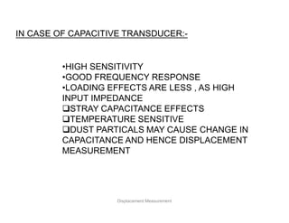
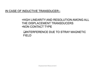
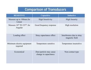
Instrumentation & Control
ME441
University Of Management &
Technology Lahore
DISPLACEMENT MEASUREMENT
CONTENTS
• INTRODUCTION
Definition
Needs of Measurement
Types of Displacement
Selection Criteria
• DISPLACEMENT TRANSDUCER
Contact Type
o Resistive Transducer
o Capacitive Transducer
o Inductive Transducer
Non Contact Type
o Ultrasonic
o IR sensor
Displacement Measurement
DEFINITION
Displacement Measurement
Being a fundamental quantity, the basic sensing
device is widely adapted with suitable linkage
for the measurement of many derived
quantities such as force , stress , pressure,
velocity and acceleration etc.
NEEDS OF MEASUREMENT
Displacement Measurement
IN THE MEASUREMENT OF PRESSURE
Displacement Measurement
FOR EXAMPLE
Pressure
Bourdon
Tube
Displacement Displacement
Transducer
Electrical
Signal
1. Linear Displacement
Linear motion measured in Few microns to few
centimetres
2. Angular Displacement
Rotational motion measured from a Few
Seconds to 360o
Displacement Measurement
TYPES OF DISPLACEMENT
For designing and selecting a displacement sensor
we must know the following questions:
 what is type of the displacement ?
 What resolution and accuracy is required ?
 What is required detection range ?
 What are the environmental conditions ?
 What is the power dissipation ?
 What is the Cost of the conditioning circuit ?
Displacement Measurement
SELECTION CRITERIA
It converts physical quantity i.e. displacement into electrical
quantity. Transducer may be consisting of two important and
closely related parts:
1. Sensing element or primary transducer
The part of the transducer which respond to a physical
phenomenon or change in the physical phenomenon.
2. Transduction element or secondary transducer
It transform the output of the sensing element to an electrical
output.
Displacement Measurement
DISPLACEMENT TRANSDUCER
Sensing
Element
Electrical
Signal
Transduction
Element
DISPLACEMENT TRANSDUCER
1. Resistance potentiometer
2. Variable inductance device
3. Differential transformer
4. Capacitive transducer
5. Hall effect sensors
6. Optical encoder
Displacement Measurement
Contact Type
1. Variable resistance
 Potentiometer
2. Variable inductance
 LVDT
 RVDT
3. Variable capacitance
Non Contact Type
1. Ultrasonic
2. IR Sensor
A number of additional types are also designed , depending upon the
convenience and measurement accuracy required.
Displacement Measurement
TYPES OF DISPLACEMENT TRANSDUCER
RESISTIVE TRANSDUCERS
Displacement Measurement
PRINCIPLE
Where
R= Resistance, Ω
ρ= Resistivity of material , Ω-m
l=length, m
A= Area, m2
A resistive transducer that works on the principle of voltage division.
A passive transducer can measure both translational as well as
rotational motions.
SLIDING CONTACT VARIABLE RESISTANCE POTENTIOMETER
Displacement Measurement
Principle: sliding contact devices utilizes variation
in effective length f wire for measurement
Mechanical displacement is input and electrical signal
as output (Voltage or current)
Large displacement can be sensed by wraping
resistance wire around a core.
Can also measure angular movement when resistance
element is formed into an arc.
MATHEMATICAL EXPRESSION FOR POTENTIOMETER
so there is a linear
relationship between
input displacement and
output voltage.
Resistive Transducer
1
1
(0,0)
It is due to resistance
of meter connected
at output of
potentiometer
Which produces non
linearity effect in the
output
Resistive Transducer
1
1
(0,0)
LOADING EFFECT
ADVANTAGES
• Inexpensive
• Simple to operate
• Requires a large force to move the
sliding contacts
• Sliding contacts can be contaminated
and can wear out.
Resistive Transducer
DISADVANTAGES
Strain Gauge
Resistance





A
l
R
A
l
R


Property of material
Length of wire
Effective cross sectional area of wire
l
R 


R
l


R
l
=>
Tension
Compression
Bending Beam Load Cell
Strain Gauge
Strain Gauge
Bending Beam Load Cell
Strain Gauge
In Tension
Strain Gauge
in compression
CAPACITIVE
TRANSDUCERS
CAPACITIVE TRANSDUCERS
0
r A
C
d
 

CAPACITIVE TRANSDUCERS
Where
C = Capacitance,
ε = ε0 εr , permittivity of the medium; F/m
ε0 = the permittivity of free space;
8.85x10⁻¹² F/m
εr = relative permittivity
A = Overlapping area of plates; m2
d = distance between the plates; m
Can measure distance of the order 1x10^-7mm
CHANGE IN CAPACITANCE MAY BE CAUSED BY
 Change in Overlapping Area, A
 Parallel Plate Capacitor
 Cylindrical Capacitor
 Angular Displacement
 Change in Distance d between the plates
 Differential Arrangement
 Change in Dielectric constant, ε
PRINCIPLE
• Parallel Plate Capacitor
CAPACITIVE TRANSDUCERS
Useful for measurement of linear displacement from 1mm to 10mm
with an accuracy of 0.005%
TRANSDUCERS USING CHANGE IN AREA OF PLATES
Sensitivity is constant, and the relationship between capacitance and
displacement is linear
 Cylindrical Capacitor
TRANSDUCERS USING CHANGE IN AREA OF PLATES
CAPACITIVE TRANSDUCERS
 The capacitance is maximum when the two plates completely overlap each
other i.e., when θ=π
 Measurement of Angular Displacement
TRANSDUCERS USING CHANGE IN AREA OF PLATES
CAPACITIVE TRANSDUCERS
TRANSDUCERS USING CHANGE IN DISTANCE BETWEEN PLATES
(0,0) Displacement
Capacitance,C
d
d
x
Fixed Plate
Moving Plate
C1, E1
C2, E2
E
Used for displacement of 10-08mm to 10 mm with an accuracy of 0.1%
 Differential Arrangement
TRANSDUCERS USING CHANGE IN DISTANCE BETWEEN PLATES
Advantages of CAPACITIVE TRANSDUCERS
CAPACITIVE TRANSDUCERS
 Extremely Sensitive
 Requires extremely small forces to operate them
 High input impedance
 Resolution of 2.5x10⁻³mm can be obtained
 Shows non linear behaviour many times on account of
edge effect
 Temperature sensitive
 Requires complex Instrumentation Circuitary.
DISADVANTAGES OF CAPACITIVE TRANSDUCERS
INDUCTIVE TRANSDUCERS
Inductive transducers use the technique of transforming the
physical quantity i.e. displacement into an electrical quantity
associated with the Magnetic circuits. Linear and Angular,
both types of displacements can be measured.
INDUCTIVE TRANSDUCERS
INTRODUCTION
Mutual Inductance
It is the phenomenon in which a
change of current in one coil
causes an induced emf in another
coil placed near to the first coil.
DIFFERENTIAL TRANSFORMER
Linear Variable Differential Transformer
INDUCTIVE TRANSDUCERS
A very basic transducer which is always useful in the field of
instrumentation. LVDT works under the principle of mutual induction.
.
DIFFERENTIAL TRANSFORMER
Rotary variable Differential Transformer
Operation of RVDT is similar to LVDT. At Null
position E output = 0. Any angular displacement
from null position will cause a differential voltage
output. Magnitude of differential voltage is
proportional to angular displacement. Phase
difference between output voltage and excitation
voltage gives direction of rotation.
INDUCTIVE TRANSDUCERS
Linear variable-differential
transformer(LVDT)
• The linear variable-differential
transformer(LVDT) is the most widely used
inductive transducer to translate linear motion
into electrical signal
33
• A differential transformer consists of a
primary winding and two secondary
windings. The windings are arranged
concentrically and next to each other.
• A ferro-magnetic core(armature) in the
shape of a rod or cylinder is attached to
the transducer sensing shaft.
34
• An a.c. excitation is applied across the
primary winding and the movable core
varies the coupling between it and the
two secondary windings.
• As the core moves away from the center
position, the coupling to one secondary
becomes more and hence its output
voltage increases, while the coupling and
the output voltage of the other
secondary decreases.
35
principle:
• Any physical displacement of the core causes the
voltage of one secondary winding to increase while
simultaneously, reducing the voltage in the other
secondary winding.
• The difference of the two voltages appears
across the output terminals of the transducers and
gives a measure of the physical position of the core
and hence the displacement.
36
Operation:
• When the core is in the neutral or zero position,
voltages induced in the secondary windings are equal
and opposite and the net output is negligible.
• By comparing the magnitude and phase of output
with input source, the amount and direction of
movement of core and hence displacement may be
determined.
37
Advantages of LVDT
• The transducers possess a high sensitivity.
• The transducers have low hysteresis and hence
repeatability is excellent under all conditions.
• They have infinite resolution.
• They are simple,light in weight and easy to maintain.
38
Disadvantages of LVDT
• They are sensitive to stray magnetic fields but
shielding is possible.
• Temperature affects the performance of transducer.
39
Uses:
• The LVDT can be used in all applications where
displacements ranging from fraction of a mm to a
few cm have to be measured.
• Acting as a secondary transducer it can be used as a
device to measure force, weight and pressure.
40
ADVANTAGES OF USING LVDT
 Frictionless measurement
 Infinite Mechanical life
 Excellent resolution
 Good repeatability
 Dynamic response
 Effect of exciting frequency
INDUCTIVE TRANSDUCERS
DISADVANTAGES OF USING LVDT
Optical Encoders
• Incremental encoder
• Absolute encoder
Displacement Measurement
CONCLUSION
Displacement Measurement
We studied many displacement type transducers:
And each transducer has its own significance with certain
drawbacks …
AS IN CASE OF RESISTIVE TRANSDUCER:-
•USED FOR LINEAR AS WELL AS ANGULAR
DISPLACEMENT.
•CAN MEASURE UPTO 100mm.
•ECONOMICAL
•HIGH OUTPUT
•MINIMUM ELECTRONICE REQUIRED
HAVING LOADING EFFECTS
Displacement Measurement
IN CASE OF CAPACITIVE TRANSDUCER:-
•HIGH SENSITIVITY
•GOOD FREQUENCY RESPONSE
•LOADING EFFECTS ARE LESS , AS HIGH
INPUT IMPEDANCE
STRAY CAPACITANCE EFFECTS
TEMPERATURE SENSITIVE
DUST PARTICALS MAY CAUSE CHANGE IN
CAPACITANCE AND HENCE DISPLACEMENT
MEASUREMENT
Displacement Measurement
IN CASE OF INDUCTIVE TRANSDUCER:-
•HIGH LINEARITY AND RESOLUTION AMONG ALL
THE DISPLACEMENT TRANSDUCERS
•NON CONTACT TYPE
INTERFERENCE DUE TO STRAY MAGNETIC
FIELD
Displacement Measurement
Comparison of Transducers
RESISTIVE Capacitive Inductive
Measure up to 100mm.for
Linear
High Sensitivity High linearity
Measure 10O TO 3570. for
Angular
Good frequency response High resolution
Loading effect Stray capacitance effect Interference due to stray
magnetic field
Minimum electric equipment
required
Temperature sensitive Temperature insensitive
Economical Dust particle may cause
change in capacitance
Non-contact type
Displacement Measurement

Lecture_6_Part_1 Displacement.pdf which on

  • 1.
    Instrumentation & Control ME441 UniversityOf Management & Technology Lahore
  • 2.
  • 3.
    CONTENTS • INTRODUCTION Definition Needs ofMeasurement Types of Displacement Selection Criteria • DISPLACEMENT TRANSDUCER Contact Type o Resistive Transducer o Capacitive Transducer o Inductive Transducer Non Contact Type o Ultrasonic o IR sensor Displacement Measurement
  • 4.
  • 5.
    Being a fundamentalquantity, the basic sensing device is widely adapted with suitable linkage for the measurement of many derived quantities such as force , stress , pressure, velocity and acceleration etc. NEEDS OF MEASUREMENT Displacement Measurement
  • 6.
    IN THE MEASUREMENTOF PRESSURE Displacement Measurement FOR EXAMPLE Pressure Bourdon Tube Displacement Displacement Transducer Electrical Signal
  • 7.
    1. Linear Displacement Linearmotion measured in Few microns to few centimetres 2. Angular Displacement Rotational motion measured from a Few Seconds to 360o Displacement Measurement TYPES OF DISPLACEMENT
  • 8.
    For designing andselecting a displacement sensor we must know the following questions:  what is type of the displacement ?  What resolution and accuracy is required ?  What is required detection range ?  What are the environmental conditions ?  What is the power dissipation ?  What is the Cost of the conditioning circuit ? Displacement Measurement SELECTION CRITERIA
  • 9.
    It converts physicalquantity i.e. displacement into electrical quantity. Transducer may be consisting of two important and closely related parts: 1. Sensing element or primary transducer The part of the transducer which respond to a physical phenomenon or change in the physical phenomenon. 2. Transduction element or secondary transducer It transform the output of the sensing element to an electrical output. Displacement Measurement DISPLACEMENT TRANSDUCER Sensing Element Electrical Signal Transduction Element
  • 10.
    DISPLACEMENT TRANSDUCER 1. Resistancepotentiometer 2. Variable inductance device 3. Differential transformer 4. Capacitive transducer 5. Hall effect sensors 6. Optical encoder Displacement Measurement
  • 11.
    Contact Type 1. Variableresistance  Potentiometer 2. Variable inductance  LVDT  RVDT 3. Variable capacitance Non Contact Type 1. Ultrasonic 2. IR Sensor A number of additional types are also designed , depending upon the convenience and measurement accuracy required. Displacement Measurement TYPES OF DISPLACEMENT TRANSDUCER
  • 12.
  • 13.
    PRINCIPLE Where R= Resistance, Ω ρ=Resistivity of material , Ω-m l=length, m A= Area, m2 A resistive transducer that works on the principle of voltage division. A passive transducer can measure both translational as well as rotational motions. SLIDING CONTACT VARIABLE RESISTANCE POTENTIOMETER
  • 14.
    Displacement Measurement Principle: slidingcontact devices utilizes variation in effective length f wire for measurement Mechanical displacement is input and electrical signal as output (Voltage or current) Large displacement can be sensed by wraping resistance wire around a core. Can also measure angular movement when resistance element is formed into an arc.
  • 15.
    MATHEMATICAL EXPRESSION FORPOTENTIOMETER so there is a linear relationship between input displacement and output voltage. Resistive Transducer 1 1 (0,0)
  • 16.
    It is dueto resistance of meter connected at output of potentiometer Which produces non linearity effect in the output Resistive Transducer 1 1 (0,0) LOADING EFFECT
  • 17.
    ADVANTAGES • Inexpensive • Simpleto operate • Requires a large force to move the sliding contacts • Sliding contacts can be contaminated and can wear out. Resistive Transducer DISADVANTAGES
  • 18.
    Strain Gauge Resistance      A l R A l R   Property ofmaterial Length of wire Effective cross sectional area of wire l R    R l   R l => Tension Compression
  • 19.
    Bending Beam LoadCell Strain Gauge Strain Gauge
  • 20.
    Bending Beam LoadCell Strain Gauge In Tension Strain Gauge in compression
  • 21.
  • 22.
    0 r A C d    CAPACITIVETRANSDUCERS Where C = Capacitance, ε = ε0 εr , permittivity of the medium; F/m ε0 = the permittivity of free space; 8.85x10⁻¹² F/m εr = relative permittivity A = Overlapping area of plates; m2 d = distance between the plates; m Can measure distance of the order 1x10^-7mm CHANGE IN CAPACITANCE MAY BE CAUSED BY  Change in Overlapping Area, A  Parallel Plate Capacitor  Cylindrical Capacitor  Angular Displacement  Change in Distance d between the plates  Differential Arrangement  Change in Dielectric constant, ε PRINCIPLE
  • 23.
    • Parallel PlateCapacitor CAPACITIVE TRANSDUCERS Useful for measurement of linear displacement from 1mm to 10mm with an accuracy of 0.005% TRANSDUCERS USING CHANGE IN AREA OF PLATES
  • 24.
    Sensitivity is constant,and the relationship between capacitance and displacement is linear  Cylindrical Capacitor TRANSDUCERS USING CHANGE IN AREA OF PLATES CAPACITIVE TRANSDUCERS
  • 25.
     The capacitanceis maximum when the two plates completely overlap each other i.e., when θ=π  Measurement of Angular Displacement TRANSDUCERS USING CHANGE IN AREA OF PLATES CAPACITIVE TRANSDUCERS
  • 26.
    CAPACITIVE TRANSDUCERS TRANSDUCERS USINGCHANGE IN DISTANCE BETWEEN PLATES (0,0) Displacement Capacitance,C
  • 27.
    d d x Fixed Plate Moving Plate C1,E1 C2, E2 E Used for displacement of 10-08mm to 10 mm with an accuracy of 0.1%  Differential Arrangement TRANSDUCERS USING CHANGE IN DISTANCE BETWEEN PLATES
  • 28.
    Advantages of CAPACITIVETRANSDUCERS CAPACITIVE TRANSDUCERS  Extremely Sensitive  Requires extremely small forces to operate them  High input impedance  Resolution of 2.5x10⁻³mm can be obtained  Shows non linear behaviour many times on account of edge effect  Temperature sensitive  Requires complex Instrumentation Circuitary. DISADVANTAGES OF CAPACITIVE TRANSDUCERS
  • 29.
  • 30.
    Inductive transducers usethe technique of transforming the physical quantity i.e. displacement into an electrical quantity associated with the Magnetic circuits. Linear and Angular, both types of displacements can be measured. INDUCTIVE TRANSDUCERS INTRODUCTION Mutual Inductance It is the phenomenon in which a change of current in one coil causes an induced emf in another coil placed near to the first coil.
  • 31.
    DIFFERENTIAL TRANSFORMER Linear VariableDifferential Transformer INDUCTIVE TRANSDUCERS A very basic transducer which is always useful in the field of instrumentation. LVDT works under the principle of mutual induction. .
  • 32.
    DIFFERENTIAL TRANSFORMER Rotary variableDifferential Transformer Operation of RVDT is similar to LVDT. At Null position E output = 0. Any angular displacement from null position will cause a differential voltage output. Magnitude of differential voltage is proportional to angular displacement. Phase difference between output voltage and excitation voltage gives direction of rotation. INDUCTIVE TRANSDUCERS
  • 33.
    Linear variable-differential transformer(LVDT) • Thelinear variable-differential transformer(LVDT) is the most widely used inductive transducer to translate linear motion into electrical signal 33
  • 34.
    • A differentialtransformer consists of a primary winding and two secondary windings. The windings are arranged concentrically and next to each other. • A ferro-magnetic core(armature) in the shape of a rod or cylinder is attached to the transducer sensing shaft. 34
  • 35.
    • An a.c.excitation is applied across the primary winding and the movable core varies the coupling between it and the two secondary windings. • As the core moves away from the center position, the coupling to one secondary becomes more and hence its output voltage increases, while the coupling and the output voltage of the other secondary decreases. 35
  • 36.
    principle: • Any physicaldisplacement of the core causes the voltage of one secondary winding to increase while simultaneously, reducing the voltage in the other secondary winding. • The difference of the two voltages appears across the output terminals of the transducers and gives a measure of the physical position of the core and hence the displacement. 36
  • 37.
    Operation: • When thecore is in the neutral or zero position, voltages induced in the secondary windings are equal and opposite and the net output is negligible. • By comparing the magnitude and phase of output with input source, the amount and direction of movement of core and hence displacement may be determined. 37
  • 38.
    Advantages of LVDT •The transducers possess a high sensitivity. • The transducers have low hysteresis and hence repeatability is excellent under all conditions. • They have infinite resolution. • They are simple,light in weight and easy to maintain. 38
  • 39.
    Disadvantages of LVDT •They are sensitive to stray magnetic fields but shielding is possible. • Temperature affects the performance of transducer. 39
  • 40.
    Uses: • The LVDTcan be used in all applications where displacements ranging from fraction of a mm to a few cm have to be measured. • Acting as a secondary transducer it can be used as a device to measure force, weight and pressure. 40
  • 41.
    ADVANTAGES OF USINGLVDT  Frictionless measurement  Infinite Mechanical life  Excellent resolution  Good repeatability  Dynamic response  Effect of exciting frequency INDUCTIVE TRANSDUCERS DISADVANTAGES OF USING LVDT
  • 42.
    Optical Encoders • Incrementalencoder • Absolute encoder Displacement Measurement
  • 43.
  • 44.
    We studied manydisplacement type transducers: And each transducer has its own significance with certain drawbacks … AS IN CASE OF RESISTIVE TRANSDUCER:- •USED FOR LINEAR AS WELL AS ANGULAR DISPLACEMENT. •CAN MEASURE UPTO 100mm. •ECONOMICAL •HIGH OUTPUT •MINIMUM ELECTRONICE REQUIRED HAVING LOADING EFFECTS Displacement Measurement
  • 45.
    IN CASE OFCAPACITIVE TRANSDUCER:- •HIGH SENSITIVITY •GOOD FREQUENCY RESPONSE •LOADING EFFECTS ARE LESS , AS HIGH INPUT IMPEDANCE STRAY CAPACITANCE EFFECTS TEMPERATURE SENSITIVE DUST PARTICALS MAY CAUSE CHANGE IN CAPACITANCE AND HENCE DISPLACEMENT MEASUREMENT Displacement Measurement
  • 46.
    IN CASE OFINDUCTIVE TRANSDUCER:- •HIGH LINEARITY AND RESOLUTION AMONG ALL THE DISPLACEMENT TRANSDUCERS •NON CONTACT TYPE INTERFERENCE DUE TO STRAY MAGNETIC FIELD Displacement Measurement
  • 47.
    Comparison of Transducers RESISTIVECapacitive Inductive Measure up to 100mm.for Linear High Sensitivity High linearity Measure 10O TO 3570. for Angular Good frequency response High resolution Loading effect Stray capacitance effect Interference due to stray magnetic field Minimum electric equipment required Temperature sensitive Temperature insensitive Economical Dust particle may cause change in capacitance Non-contact type
  • 48.