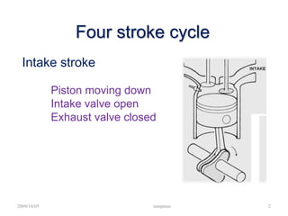
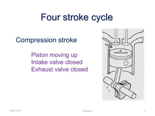
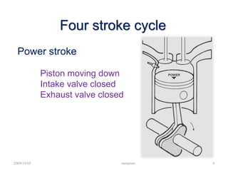
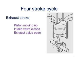
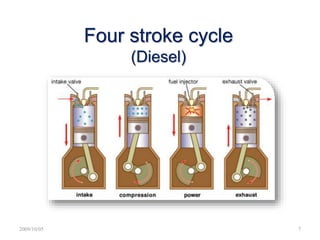
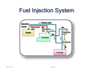
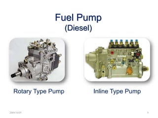
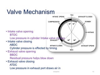
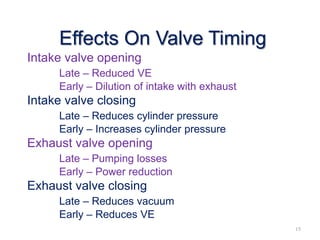
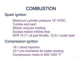
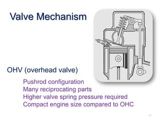
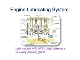
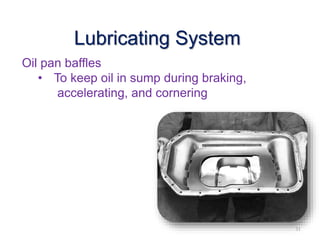
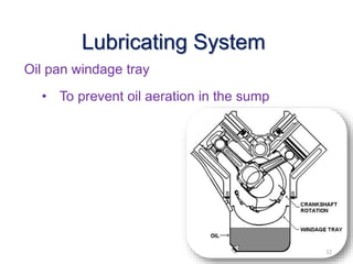
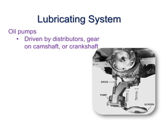
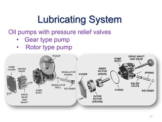
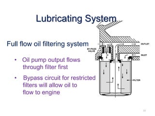
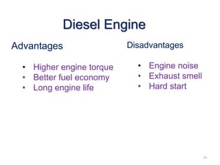
Four Stroke Engine
Operation
Four stroke cycle
Intake stroke
Piston moving down
Intake valve open
Exhaust valve closed
2009/10/05 mmpmm 2
Compression stroke
Piston moving up
Intake valve closed
Exhaust valve closed
Four stroke cycle
2009/10/05 mmpmm 3
Power stroke
Piston moving down
Intake valve closed
Exhaust valve closed
Four stroke cycle
2009/10/05 mmpmm 4
Exhaust stroke
Piston moving up
Intake valve closed
Exhaust valve open
Four stroke cycle
5
• Each stroke takes 180° of
crankshaft rotation to complete
• All cylinders fire in 720° of
crankshaft rotation
• 720 divided by number of
cylinders = firing interval
• Odd fire V-6 engine (90° block
with 120° rod journals)
Four stroke cycle
(Petrol)
6
2009/10/05 7
Four stroke cycle
(Diesel)
2009/10/05 mmpmm 8
Fuel Injection System
2009/10/05 9
Fuel Pump
(Diesel)
Rotary Type Pump Inline Type Pump
2009/10/05 mmpmm 10
Fuel Feed Pump
Draw fuel from tank and
feed to injection pump
11
Engine Cooling System
Engine heat is transferred
through walls of the
combustion chambers and
through the walls of cylinders
Piston Dwell Time
Piston travel is at a minimum
TDC and BDC
Crank moves horizontally
Piston velocity
Maximum when rod is 90° to crank
Acceleration
Maximum 30° earlier
Best VE is obtained by synchronizing valve
opening with piston speeds
12
Other Valve Position
Overlap
• Both valves are open
• End of exhaust & start of intake
• Low pressure in exhaust port
Blow down
• Exhaust valve opens before BDC
• To help evacuate cylinder before piston
reverses
• Pumping losses at end of exhaust
stroke
13
Valve Mechanism
• Intake valve opening
BTDC
Low pressure in cylinder Intake valve closing
• Intake valve closing
ABDC
Cylinder pressure is effected by timing
• Exhaust valve opening
BBDC
Residual pressure helps blow down
• Exhaust valve closing
ATDC
Low pressure in exhaust port draws air in
mmpmm 14
Effects On Valve Timing
Intake valve opening
Late – Reduced VE
Early – Dilution of intake with exhaust
Intake valve closing
Late – Reduces cylinder pressure
Early – Increases cylinder pressure
Exhaust valve opening
Late – Pumping losses
Early – Power reduction
Exhaust valve closing
Late – Reduces vacuum
Early – Reduces VE
15
COMBUSTION
Spark ignition
Maximum cylinder pressure 15° ATDC
Tumble and swirl
Motion reduces misfires
Excess motion inhibits flow
AFR 14.7:1 at part throttle, 12.5:1 under load
Compression ignition
18:1 direct injection
23:1 pre-chambers for better starting
Compression heats to 800-1200 °F
16
Valve Mechanism
OHV (overhead valve)
Pushrod configuration
Many reciprocating parts
Higher valve spring pressure required
Compact engine size compared to OHC
17
OHC (overhead cam)
Fewer reciprocating parts
Reduced valve spring pressure required
Higher RPM capability
Cylinder head assemblies are taller
18
Valve Mechanism
Cam-in-head
No pushrods
Use rocker arms
19
Valve Mechanism
Valve lash compensators
Solid lifters
No internal parts
Periodic adjustment
20
Hydraulic lifters
To maintain zero lash
Quieter No periodic
adjustment
Anti-scuff additives
are required in oils
Valve lash compensators
21
Hydraulic lifter operation
Valve closed
• Oil flows through lifter
bore & past check
valve
• Plunger return spring
maintains zero lash
22
Valve open
• Check valve seats
and limits the slippage
• Now operates as a
solid lifter
Hydraulic lifter operation
23
Hydraulic lifter operation
Return to valve closed
• New oil enters the lifter
body
• This oil replaces oil
that has leaked
between plunger and
body (predetermined
leakage)
24
Metering Device
Metering valve meters the
oil flow to the pushrod
25
Gear sets
• Cam and crank rotate in opposite directions
• Noisy if not free of burrs
• Helical and spur cut gears 26
Timing Gear Wheel sets
Timing chains
• Single and double roller
• Tension Pulley
27
Timing Belt sets
Timing belts
• Require maintenance
• Silent operation
28
Timing Chain Drive
29
Engine Lubricating System
Lubrication with oil through pressure
to every moving parts
Splash and spray
30
Lubricating System
Oil pan baffles
• To keep oil in sump during braking,
accelerating, and cornering
31
Lubricating System
Oil pan windage tray
• To prevent oil aeration in the sump
32
Lubricating System
Oil pumps
• Driven by distributors, gear
on camshaft, or crankshaft
33
Lubricating System
Oil pumps with pressure relief valves
• Gear type pump
• Rotor type pump
34
Lubricating System
Full flow oil filtering system
• Oil pump output flows
through filter first
• Bypass circuit for restricted
filters will allow oil to
flow to engine
35
Lubricating System
Diesel Engine
Advantages
• Higher engine torque
• Better fuel economy
• Long engine life
Disadvantages
• Engine noise
• Exhaust smell
• Hard start
36

4 stroke engine

  • 1.
  • 2.
    Four stroke cycle Intakestroke Piston moving down Intake valve open Exhaust valve closed 2009/10/05 mmpmm 2
  • 3.
    Compression stroke Piston movingup Intake valve closed Exhaust valve closed Four stroke cycle 2009/10/05 mmpmm 3
  • 4.
    Power stroke Piston movingdown Intake valve closed Exhaust valve closed Four stroke cycle 2009/10/05 mmpmm 4
  • 5.
    Exhaust stroke Piston movingup Intake valve closed Exhaust valve open Four stroke cycle 5
  • 6.
    • Each stroketakes 180° of crankshaft rotation to complete • All cylinders fire in 720° of crankshaft rotation • 720 divided by number of cylinders = firing interval • Odd fire V-6 engine (90° block with 120° rod journals) Four stroke cycle (Petrol) 6
  • 7.
  • 8.
    2009/10/05 mmpmm 8 FuelInjection System
  • 9.
    2009/10/05 9 Fuel Pump (Diesel) RotaryType Pump Inline Type Pump
  • 10.
    2009/10/05 mmpmm 10 FuelFeed Pump Draw fuel from tank and feed to injection pump
  • 11.
    11 Engine Cooling System Engineheat is transferred through walls of the combustion chambers and through the walls of cylinders
  • 12.
    Piston Dwell Time Pistontravel is at a minimum TDC and BDC Crank moves horizontally Piston velocity Maximum when rod is 90° to crank Acceleration Maximum 30° earlier Best VE is obtained by synchronizing valve opening with piston speeds 12
  • 13.
    Other Valve Position Overlap •Both valves are open • End of exhaust & start of intake • Low pressure in exhaust port Blow down • Exhaust valve opens before BDC • To help evacuate cylinder before piston reverses • Pumping losses at end of exhaust stroke 13
  • 14.
    Valve Mechanism • Intakevalve opening BTDC Low pressure in cylinder Intake valve closing • Intake valve closing ABDC Cylinder pressure is effected by timing • Exhaust valve opening BBDC Residual pressure helps blow down • Exhaust valve closing ATDC Low pressure in exhaust port draws air in mmpmm 14
  • 15.
    Effects On ValveTiming Intake valve opening Late – Reduced VE Early – Dilution of intake with exhaust Intake valve closing Late – Reduces cylinder pressure Early – Increases cylinder pressure Exhaust valve opening Late – Pumping losses Early – Power reduction Exhaust valve closing Late – Reduces vacuum Early – Reduces VE 15
  • 16.
    COMBUSTION Spark ignition Maximum cylinderpressure 15° ATDC Tumble and swirl Motion reduces misfires Excess motion inhibits flow AFR 14.7:1 at part throttle, 12.5:1 under load Compression ignition 18:1 direct injection 23:1 pre-chambers for better starting Compression heats to 800-1200 °F 16
  • 17.
    Valve Mechanism OHV (overheadvalve) Pushrod configuration Many reciprocating parts Higher valve spring pressure required Compact engine size compared to OHC 17
  • 18.
    OHC (overhead cam) Fewerreciprocating parts Reduced valve spring pressure required Higher RPM capability Cylinder head assemblies are taller 18 Valve Mechanism
  • 19.
    Cam-in-head No pushrods Use rockerarms 19 Valve Mechanism
  • 20.
    Valve lash compensators Solidlifters No internal parts Periodic adjustment 20
  • 21.
    Hydraulic lifters To maintainzero lash Quieter No periodic adjustment Anti-scuff additives are required in oils Valve lash compensators 21
  • 22.
    Hydraulic lifter operation Valveclosed • Oil flows through lifter bore & past check valve • Plunger return spring maintains zero lash 22
  • 23.
    Valve open • Checkvalve seats and limits the slippage • Now operates as a solid lifter Hydraulic lifter operation 23
  • 24.
    Hydraulic lifter operation Returnto valve closed • New oil enters the lifter body • This oil replaces oil that has leaked between plunger and body (predetermined leakage) 24
  • 25.
    Metering Device Metering valvemeters the oil flow to the pushrod 25
  • 26.
    Gear sets • Camand crank rotate in opposite directions • Noisy if not free of burrs • Helical and spur cut gears 26 Timing Gear Wheel sets
  • 27.
    Timing chains • Singleand double roller • Tension Pulley 27 Timing Belt sets
  • 28.
    Timing belts • Requiremaintenance • Silent operation 28 Timing Chain Drive
  • 29.
    29 Engine Lubricating System Lubricationwith oil through pressure to every moving parts
  • 30.
  • 31.
    Oil pan baffles •To keep oil in sump during braking, accelerating, and cornering 31 Lubricating System
  • 32.
    Oil pan windagetray • To prevent oil aeration in the sump 32 Lubricating System
  • 33.
    Oil pumps • Drivenby distributors, gear on camshaft, or crankshaft 33 Lubricating System
  • 34.
    Oil pumps withpressure relief valves • Gear type pump • Rotor type pump 34 Lubricating System
  • 35.
    Full flow oilfiltering system • Oil pump output flows through filter first • Bypass circuit for restricted filters will allow oil to flow to engine 35 Lubricating System
  • 36.
    Diesel Engine Advantages • Higherengine torque • Better fuel economy • Long engine life Disadvantages • Engine noise • Exhaust smell • Hard start 36