Download to read offline


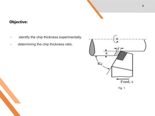
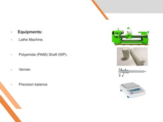
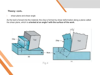
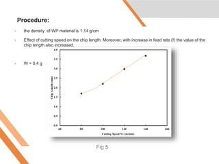
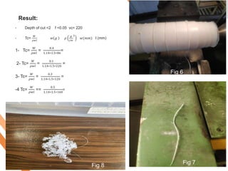
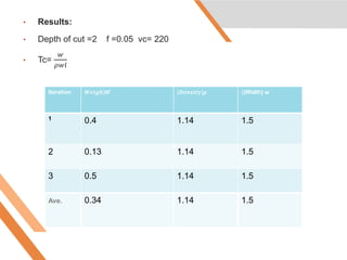

1. The document describes an experiment to calculate the chip thickness ratio when machining a polyamide shaft on a lathe machine. Key measurements taken include workpiece weight before and after cutting, width of cut, and length of chip. 2. Chip thickness ratio is defined as the thickness of the metal before cutting divided by the thickness after cutting. Important factors that influence chip thickness include cutting speed, feed rate, depth of cut, and tool geometry. 3. Preliminary results show that with increasing cutting speed and feed rate, the chip thickness ratio decreases, meaning more material is removed in the cut. The average calculated ratio from the initial tests was 0.34.


