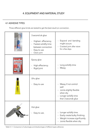
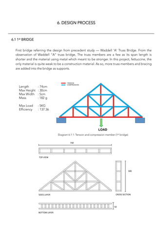
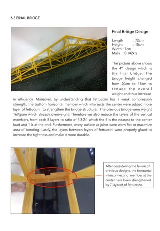
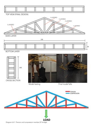
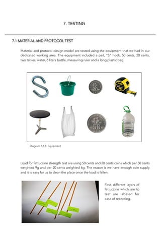
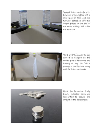
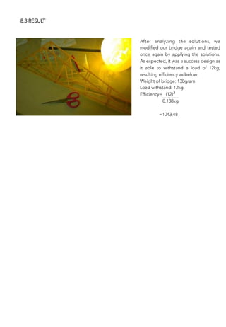
This document outlines a student project to design and build a fettuccine truss bridge model. It discusses conducting a precedent study of an existing truss bridge, the Waddell "A" truss bridge. It also describes testing different fettuccine brands and adhesives to determine the strongest materials. The project involves designing, building, and testing multiple bridge models, making modifications between tests to improve strength.
Advanced Design of Composite Steel-Concrete Structural elementIJERA Editor
Composite framing system consisting of steel beams acting interactively with metal deck-concrete slab and concrete encased composite columns, has been as a viable alternative to the conventional steel or reinforced concrete system in the high-rise construction. However, in Indian context, it is comparatively new and no appropriate design codes are available for the same. Complications in the analysis and design of composite structures have led numerous researchers to develop simplified methods so as to eliminate a number of large scale tests needed for the design. In the present work, a simplified method of composite slabs, beams and columns design is used and software is developed with pre- and post- processing facilities in VB.NET. All principal design checks are incorporated in the software. The full and partial shear connection and the requirement for transverse reinforcement are also considered. To facilitate direct selection of steel section, a database is prepared and is available at the back end with the properties of all standard steel sections. Screen shots are included in the paper to illustrate the method employed for selecting the appropriate section and shear connectors and thus to verify the design adequacy.
Civil Engineering : Rcc & steel structures, THE GATE ACADEMYklirantga
THE GATE ACADEMY's GATE Correspondence Materials consist of complete GATE syllabus in the form of booklets with theory, solved examples, model tests, formulae and questions in various levels of difficulty in all the topics of the syllabus. The material is designed in such a way that it has proven to be an ideal material in-terms of an accurate and efficient preparation for GATE.
Quick Refresher Guide : is especially developed for the students, for their quick revision of concepts preparing for GATE examination. Also get 1 All India Mock Tests with results including Rank,Percentile,detailed performance analysis and with video solutions
GATE QUESTION BANK : is a topic-wise and subject wise collection of previous year GATE questions ( 2001 – 2013). Also get 1 All India Mock Tests with results including Rank,Percentile,detailed performance analysis and with video solutions
Lecture - 01: Introduction to Reinforced Concrete DesignHezb
Lectures can be downloaded from Prof. Dr. Qaisar Ali's personal website:
http://www.drqaisarali.com
This is first lecture of the series of lectures delivered by Prof. Dr. Qaisar Ali, in the Reinforced Concrete Design Course. The first lecture introduces various concepts related to structural designing. It also introduce ACI Code and provides a stepwise procedure for analysis and subsequent flexure and shear design of a beam.
Precast concrete is a construction product produced by casting concrete in a reusable mold or "form" which is then cured in a controlled environment. transported to the construction site and lifted into place. In contrast, standard concrete is poured into site-specific forms and cured on site.
Concrete filled steel tubes subjected to axial compressioneSAT Journals
Abstract Concrete-filled steel tubular columns have excellent earth-quake resistant properties such as high strength and ductility and large energy absorption capacity. For concrete-filled steel tubes (CFST), local buckling commonly observed in bare steel columns is effectively prevented, giving a higher capacity. However if the concrete core and the steel tube are loaded simultaneously the steel tube expands more than the concrete core under moderate loads since Poisson’s ratio is higher for the steel section. The objective of this paper is To evaluate the accuracy of codal design approach by comparing experimental results with the analytical results obtained using EC4, ACI-318 and AISC-LRFD, for prediction of load carrying capacity of CFST columns under axial compression. Based on this the experimental programme is conducted on concrete filled steel tubes of length 300mm, thickness 1 to 3mm for circular, square and rectangular cross section with three different grades of concrete.200 T capacity Compression testing machine is used for experimental investigation.. The experimental results are compared with analytical results obtained by stated code of practices. From this it is concluded that EC4 gives conservative results. From which it is observed that EC4 gives conservative results with experimental results and it is concluded that EC4 provisions may be used for further analytical study to develop an expression to predict the section capacity CFST columns. As the grade of concrete increases the load carrying capacity is also increases. This paper presents the details of study carried out and the conclusions arrived. Keywords: CFST, high strength, local buckling, analytical, ACI-318, EC4, AISC-LRFD.
Wearables are going to transform the way people and enterprises work and touch almost every enterprise vertical market.
Learn how to build useful solutions by combining Mobile, Cognitive and Wearables technologies and get access to free tools that will help you build your own cognitive wearable solution.
Madison+ UX 2014: A/B Testing - The Good, The Bad, and The Uglycoreyloose
A/B testing is a great technique to experiment with changes to your product. At Etsy we make extensive use of them to test out ideas; we’ve got 30+ running right now. Although the concept is simple, the execution is a bit tricker then you’d think. In this talk I will cover the common, and a few of the not so common, mistakes that can skew your results.
2024.06.01 Introducing a competency framework for languag learning materials ...Sandy Millin
http://sandymillin.wordpress.com/iateflwebinar2024
Published classroom materials form the basis of syllabuses, drive teacher professional development, and have a potentially huge influence on learners, teachers and education systems. All teachers also create their own materials, whether a few sentences on a blackboard, a highly-structured fully-realised online course, or anything in between. Despite this, the knowledge and skills needed to create effective language learning materials are rarely part of teacher training, and are mostly learnt by trial and error.
Knowledge and skills frameworks, generally called competency frameworks, for ELT teachers, trainers and managers have existed for a few years now. However, until I created one for my MA dissertation, there wasn’t one drawing together what we need to know and do to be able to effectively produce language learning materials.
This webinar will introduce you to my framework, highlighting the key competencies I identified from my research. It will also show how anybody involved in language teaching (any language, not just English!), teacher training, managing schools or developing language learning materials can benefit from using the framework.
A Strategic Approach: GenAI in EducationPeter Windle
Artificial Intelligence (AI) technologies such as Generative AI, Image Generators and Large Language Models have had a dramatic impact on teaching, learning and assessment over the past 18 months. The most immediate threat AI posed was to Academic Integrity with Higher Education Institutes (HEIs) focusing their efforts on combating the use of GenAI in assessment. Guidelines were developed for staff and students, policies put in place too. Innovative educators have forged paths in the use of Generative AI for teaching, learning and assessments leading to pockets of transformation springing up across HEIs, often with little or no top-down guidance, support or direction.
This Gasta posits a strategic approach to integrating AI into HEIs to prepare staff, students and the curriculum for an evolving world and workplace. We will highlight the advantages of working with these technologies beyond the realm of teaching, learning and assessment by considering prompt engineering skills, industry impact, curriculum changes, and the need for staff upskilling. In contrast, not engaging strategically with Generative AI poses risks, including falling behind peers, missed opportunities and failing to ensure our graduates remain employable. The rapid evolution of AI technologies necessitates a proactive and strategic approach if we are to remain relevant.
Macroeconomics- Movie Location
This will be used as part of your Personal Professional Portfolio once graded.
Objective:
Prepare a presentation or a paper using research, basic comparative analysis, data organization and application of economic information. You will make an informed assessment of an economic climate outside of the United States to accomplish an entertainment industry objective.
Operation “Blue Star” is the only event in the history of Independent India where the state went into war with its own people. Even after about 40 years it is not clear if it was culmination of states anger over people of the region, a political game of power or start of dictatorial chapter in the democratic setup.
The people of Punjab felt alienated from main stream due to denial of their just demands during a long democratic struggle since independence. As it happen all over the word, it led to militant struggle with great loss of lives of military, police and civilian personnel. Killing of Indira Gandhi and massacre of innocent Sikhs in Delhi and other India cities was also associated with this movement.
How to Make a Field invisible in Odoo 17Celine George
It is possible to hide or invisible some fields in odoo. Commonly using “invisible” attribute in the field definition to invisible the fields. This slide will show how to make a field invisible in odoo 17.
Safalta Digital marketing institute in Noida, provide complete applications that encompass a huge range of virtual advertising and marketing additives, which includes search engine optimization, virtual communication advertising, pay-per-click on marketing, content material advertising, internet analytics, and greater. These university courses are designed for students who possess a comprehensive understanding of virtual marketing strategies and attributes.Safalta Digital Marketing Institute in Noida is a first choice for young individuals or students who are looking to start their careers in the field of digital advertising. The institute gives specialized courses designed and certification.
for beginners, providing thorough training in areas such as SEO, digital communication marketing, and PPC training in Noida. After finishing the program, students receive the certifications recognised by top different universitie, setting a strong foundation for a successful career in digital marketing.
Biological screening of herbal drugs: Introduction and Need for
Phyto-Pharmacological Screening, New Strategies for evaluating
Natural Products, In vitro evaluation techniques for Antioxidants, Antimicrobial and Anticancer drugs. In vivo evaluation techniques
for Anti-inflammatory, Antiulcer, Anticancer, Wound healing, Antidiabetic, Hepatoprotective, Cardio protective, Diuretics and
Antifertility, Toxicity studies as per OECD guidelines
Model Attribute Check Company Auto PropertyCeline George
In Odoo, the multi-company feature allows you to manage multiple companies within a single Odoo database instance. Each company can have its own configurations while still sharing common resources such as products, customers, and suppliers.
1. BUILDING STRUCTURES [ARC 2522] PROJECT 1
LEE YIANG SIANG (DEAN)
WONG SOON FOOK
LING TECK ONG
PRO WEI KEAT
CHUNG KA SENG
WONG KIEN HOU 0312104
LECTURER MR. ADIB
0302966
0302953
0303127
0303646
0316922
FETTUCCINE TRUSS BRIDGE
TAYLOR’S UNIVERSITY
SCHOOL OF ARCHITECTURE, BUILDING & DESIGN
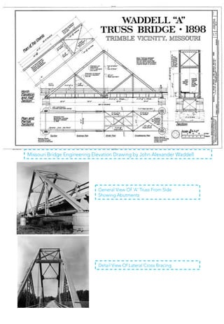
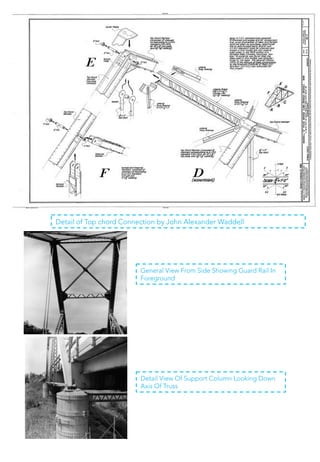
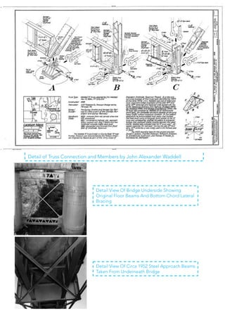
PRECEDENT STUDY: WADDELL “A” TRUSS BRIDGE, PARKVILLE, MISSOURI.
2. CONTENT
1. Introduction
1.1 General purpose of study
1.2 Report preview
1.3 Restriction
1.4 Working schedule
2. Methodology
2.1 Precedent study
2.2 Making of fettuccine truss
bridge
2.3 Structural analysis
3. Precedent Studies
4. Equipment & Material
Study
4.1 Adhesive types
4.2 Material strength study
4.2.1 Fettuccine types
and strength
test
4.2.2 Gluing method
4.2.3 Orientation
5. Model Making
5.1 Method of construction
5.2 Joint
6. Design Process
6.1 1st Bridge
6.2 2nd Bridge
6.3 3rd Bridge
6.4 Final Bridge
7. Testing
7.1 Material and protocol test
7.2 Final model test
7.2.1 Observation
7.2.2 Efficiency
8. Design Modification
8.1 Failure reasoning
8.2 Solution
8.3 Result
9. Conclusion
10. References
11. Appendix
11.1 Detail of Missouri Bridge
11.2 Truss analysis exercise
3. 1. INTRODUCTION
1.1 GENERAL PURPOSE OF STUDY
This project purposely aims to develop the understanding of tension and compressive
strength of construction materials and thus be able to evaluate, explore and improve
attributes of construction materials. Besides, this study also purpose to develop
understanding of force distribution in a truss by exploring and apply understanding of
load distribution in a truss. In this project, the ability of designing a truss bridge with high
level of aesthetic value but minimal construction material is to be learnt. Moreover,
through the process of designing fettuccine truss bridge, exploration will be taken on
different arrangement of members in a truss structure thus able to evaluate and identify
tension and compression members in a truss structure.
1.2 REPORT PREVIEW
In a group of 6, a precedent study of a truss bridge are required to carry out. Next, a
fettuccine truss bridge of 600mm clear span and with maximum of 150g based on the
gathered info from the precedent study. In this report, the precedent study, Waddell “A”
truss bridge located in Parkville, Missouri is studied and analysis on strength of the
material used load transfer system and truss system of this precedent study is stated in
this report. Before building the fettuccine bridge, a method of researching the strength
of the material in different brands and experiment on creating joints is taken. Besides, a
set of testing result of our truss bridge model is carried out and the designated bridge is
showed. Calculation regarding the given questions in exercise 1 is also included in the
last few page.
4. 1.3 RESTRICTION
Fettuccine is the only material that can be used to build the model bridge and we are
required to construct it with 600mm clear span and maximum weight of 150g.
1.4 WORKING SCHEDULE
Date
Tasks
2 April 2014
Buy material and prepare equipment
3 April 2014
Fettuccine strength test
8 April 2014
Case study and fettuccine strength test
9 April 2014
Construct 1st bridge
13 April 2014
Testing 1st bridge
16 April 2014
Construct 2nd bridge
17 April 2014
Testing 2nd bridge
20 April 2014
Construct 3rd bridge
21 April 2014
Testing 3rd bridge
24 April 2014
Construct final bridge
25 April 2014
Final bridge testing
Table 1.4.1: Working schedule
5. 2. METHODOLOGY
2.1 PRECEDENT STUDY
To study on the precedent study, Waddell “A” truss bridge, research is taken from the
source of internet and books. Looking at the detail of the precedent study, a real truss
bridge connections, arrangement of members and orientation of each member is to be
studied and put into the truss model structure design. Thus, the truss model’s structure
will be depended on the information obtained from the precedent studies.
2.2 MAKING OF FETTUCCINE TRUSS BRIDGE
PHASE 1: MATERIAL STRENGTH TESTING
Main material of doing the model bridge is fettuccine and the secondary, adhesive to
stick the fettuccine together as a whole structure. It is important to test different brands
of fettuccine to see their strength of taking load before skipping to the next
phase ,model making. Data showing the fettuccine strength results in different
circumstances is recorded in the subtopic of material under the topic, Analysis.
PHASE 2: CHOOSING ADHESIVE
Adhesive that is used to bond the fettuccine together might affect the strength of whole
structure .There are various choices of glue with different characteristics that could have
change the physical strength of fettuccine. As so it is crucial to choose the right
adhesive.
6. PHASE 3: MODEL MAKING
Based on the obtained information, we tried to apply some improvement on the truss
bridge model. To build a perfect model, it is first to produce an Autocad drawing of the
design model to be printed out into 1:1 scale and build it based on the cad drawing.
Jointing of the model bridge will be further discussed under the topic of truss analysis.
PHASE 4: MODEL TESTING
Finished model is tested by applying load with string attached to the middle of the
intermediate member of the model with the restriction of 60 cm clear span. Model are
tested and improved into the final designated model.
2.3 STRUCTURAL ANALYSIS
Structure model Is analyze to show the understanding of the truss and its load transfer
system. Failure models are analyzed to discover the problem and the analysis is the
reference to the next model bridge. In structural analysis, calculation and load transfer
diagrams are show.
7. 3. PRECEDENT STUDY
2.1 PRECEDENT STUDY
To study on the precedent study, Waddell “A” truss bridge, research is taken from the
source of internet and books. Looking at the detail of the precedent study, a real truss
bridge connections, arrangement of members and orientation of each member is to be
studied and put into the truss model structure design. Thus, the truss model’s structure
will be depended on the information obtained from the precedent studies.
Missouri Bridge
Waddell A Truss
History Background
Built 1898 for the Quincy, Omaha and Kansas City Railway. Abandoned in 1939, but
converted into a highway bridge on MO 4 in 1953. Dismantled in 1980 to make room for
Smithville Reservoir, but relocated to English Landing Park in Parkville in 1987.
Through truss bridge originally spanning Linn Branch Creek in Clinton County near
Trimble, but relocated to English Landing Park in Parkville spanning Rush Creek open to
pedestrians only.
8. Bottom Chord
Cross Brace
Diagonal
Hip Vertical
Top Brace
End Post
Middle Chord
Design Strategies
The waddell‘A’truss bridge is identified by the Historic American Engineering Record.
Designed and patented by the famous American Engineer John Alexander Low Waddell,
the ‘A’truss is a significant type of late 19th century, short-span railroad bridge that used
pin-connections to join its major structural members. Because of its great height the
‘A’truss of this type of Bridge are great rigidity in all directions, ease and cheapness of
erection and economy of metal when it is compared with structures of other types having
equal strength and rigidity.
Compression
Tension
Force Distribution
Truss Connection
Diagram 4.2.7: Identification of members in Waddell “A” truss bridge.
9. View From through Bridge
Southwestern Portal
Bridge Dateplate
Overview Looking North
Comparison between Previous and Present site
Built 1898 for the Quincy, Omaha and Kansas City Railway. Abandoned in 1939, but
converted into a highway bridge on MO 4 in 1953. Dismantled in 1980 to make room for
Smithville Reservoir, but relocated to English Landing Park in Parkville in 1987.
Present Site Parkville 1987 - present
Barrel Shot With Dateplate In
Right Foreground
Steel Approach Beams View
From Underneath Bridge
Approach View
Previous Site Kansas 1898 - 1939
10. Missouri Bridge Engineering Elevation Drawing by John Alexander Waddell
General View Of 'A' Truss From Side
Showing Abutments
Detail View Of Lateral Cross Bracing
11. Detail of Top chord Connection by John Alexander Waddell
General View From Side Showing Guard Rail In
Foreground
Detail View Of Support Column Looking Down
Axis Of Truss
12. Detail of Truss Connection and Members by John Alexander Waddell
Detail View Of Bridge Underside Showing
Original Floor Beams And Bottom Chord Lateral
Bracing
Detail View Of Circa 1952 Steel Approach Beams
Taken From Underneath Bridge
13. 4. EQUIPMENT AND MATERIAL STUDY
4.1 ADHESIVE TYPES
Three different glue kinds are tested to get the best result on connection.
3 second ok glue
- Highest effieciency.
- Fastest solidify time
between connection
- Easy to use
- Clean joint
Epoxy glue
- High effieciency.
- Rigid joint
Uhu glue
- Easy to use
Hot glue
- Easy to use.
- Expand and bending
might occurs
- Cracked joint after store
for a few days.
- Long solidify time
- Messy
- Messy if not control
well
- Joints slightly flexible
when dry
- Longer solidify time
than 3 seconds glue
- Longer solidify time.
- Easily create bulky finishing
- Weight increase significantly
- Joints flexible when dry
Table 4.1.1: Comparison of advantages and disadvantages of different types adhesives
14. Type
of
Glue
Glue
applied
(on
fe0uccine)
Clear
Span
(mm)
Length
(mm)
Layer
of
S;cks
No.
of
50$
coins
No.
of
20$
coins
Weight
Sustained
(g)
UHU Whole 20 24 2 16 38 364.70
3
Sec
Glue
Whole 20 24 2 16 24 285.12
From the table above, Uhu glue is obviously better than 3 seconds glue even
though Uhu needs more time to solidify the connection. This is because Uhu does
not solidify the connection thoroughly and causes to preserve the elasticity of the
fettuccine thus can sustained more stress form the load.
Type
of
Glue
Glue
applied
(Point)
Clear
Span
(mm)
Length
(mm)
Layer
of
S;cks
No.
of
50$
coins
No.
of
20$
coins
Weight
Sustained
(g)
UHU Whole 20 24 2 16 38 112.79
3
Sec
Glue
Whole 20 24 2 16 24 285.12
The results of the second test seems totally different from the first test, which on
the first test: Uhu is better than 3 second glue , whereas on the second test where
the fettuccines are to let dry for more than one day: 3 seconds glue has the better
quality. Besides, in terms of workmanships, 3 second glue leave no tracks which
made it the best choice among all the glue types.
Table 4.1.2: strength of fettuccine after applied with UHU and 3 seconds glue and tested within a day.
Table 4.1.3: The second test on glued fettuccine let to dry for more than one day.
In addition, we discovered that the stick that using Uhu glue to connect are
separated when second test is carrying out. This proves that Uhu glue does not
bond the fettuccine well as it separate into two after it was left dry for two days.
15. Days
to left
dry
Type
of
Glue
Glue
applied
(Point)
Clear
Span
(mm)
Length
(mm)
Layer
of
S;cks
Weight
Sustained
(g)
1 3
Sec
Glue
Whole 20 24 2 285.12
3 3
Sec
Glue
Whole 20 24 2 101.37
The table shows that the strength of fettuccine falls sharply after three days left to
dry. This is because the 3 second glue make the fettuccine oxidized and brittle. As
a conclusion, the truss bridge has to be done freshly one day or two before the
model test as to prevent the oxidization happened on the bridge.
Table 4.1.3: Third test shows comparison of the fettuccine’s strength after let dry
for different amount of days.
16. 4.2 MATERIAL STRENGTH STUDY
4.2.1 FETTUCCINE TYPES AND STRENGTH TEST
Several tests on material strength is carried out to identify which brands or which
type of material does the best to be the members of the bridge.
Since fettuccine is the only material that can be used to construct the bridge, its
attribute is required to be studied and tested before making the model. The way of
putting or joining fettuccine could affect the whole structure bridge.
To build a strong bridge, it is crucial to know which fettuccine’s brand can be used
and has the strongest strength to withstand load. Below are three different brands
of fettuccine and each brand is tested with load hanging on one stick of fettuccine.
Image
Name
Weight
sustained
Shape/ Section
of fettuccine
Barilla
187g
San Remo
156g
Kimball
112g
From the diagram above, it is obviously stated that the strongest fettuccine is
Barilla, followed by San Remo and Kimball. Barilla brand’s fettuccine has the utmost
strength mostly because of the expanded shape of the fettuccine. Yet, the unique
shape of the fettuccine has bring the disadvantage on making bond with another
fettuccine and its strength may fall when stack with two or more straps.
Table 4.2.1: Fettuccine types with description.
17. The capacity of the bonding is too small which may cause the the fettuccine to fall apart
when light force is applied.
Barilla fettuccine (2 stacks)
Light
Force
The fettuccine is flatter thus the capacity of the bonding is big enough which make the
fettuccine hard to break apart when light force is applied.
As a conclusion, we eliminates Barilla as the bridge material and choose San Remo
because of its higher physical strength and bigger capacity to stack on to create stronger
bond. In addition, the flatter shape of San Remo fettuccine will easy our work on building
the truss bridge.
San Remo fettuccine (2 stacks)
Light
Force
Diagram 4.2.4: Result of two layer San Remo fettuccine after light force is applied.
Diagram 4.2.3: Result of two layer Barilla fettuccine after light force is applied.
18. 4.2.2 GLUING METHOD
Several gluing method are tested to determine which method does the best by not
destruct or affect the strength of fettuccine.
3
Sec
Glue
2
Points 20 24 2 16 10 149.28
3
Points 20 24 2 16 18 250.90
Whole 20 24 2 16 24 285.12
Diagram 4.2.5: 3 seconds glue is applied at the end point of a fettuccine stick.
Diagram 4.2.6: 3 seconds glue is applied at the end point and the middle point of
a fettuccine stick.
Diagram 4.2.7: 3 seconds glue is applied wholly on a fettuccine stick.
Table 4.2.2: 3 different gluing method to show comparison.
Table above shows that the gluing method of 3 seconds glue apply wholly on
fettuccine works the best, followed by 3 interval points and then 2 interval points. In
addition, 2 points and 3 points method which does not glue the whole fettuccine
had left some unglue space to be flexible. In this case after the glued fettuccine is
let to dried for one day, observation shows expanding and bending occurs.
19. Type
of
Glue Layer
of
S;cks
Glue
Applied Weight
Sustained
(Horizontal)
(g)
Weight
Sustained
(Ver;cal)
(g)
3
Sec
Glue 2 Whole 285.12 355.45
3 Whole 395.13 450.28
4 Whole 453.72 533.34
5 Whole 589.33 522.56
4.2.3 ORIENTATION
Testing on the orientation of fettuccine (horizontally or vertically) helps to
determine which placing position would have more strength to be put into our
model design.
Horizontal orientation Vertical orientation
Diagram 4.2.8: Horizontal and vertical orientation of fettuccine.
Table 4.2.3: Comparison of horizontal and vertical orientation with the increasing
amount of layer.
Outcome of the test shows when fettuccine members are to stack to 4 layers, it is
best to use vertical orientation, whereas horizontal orientation is suitable for 5
layers of fettuccine.
20. 5. MODEL MAKING
5.1 METHOD OF CONSTRUCTION
1)
Cut 3 pieces of 24cm
length fettuccine to form
the base.
2)
Use a 5cm piece to glue the main base together.
Place a 15cm piece in the middle and connect
the triangle with two other 40cm pieces.
Put straight
trusses after
every 9cm
interval on
t h e m a i n
base.
3)
21. 4)
Then, connect pieces from the middle towards each vertical truss,
5)
Thicken the truss
afterwards. The
bottom base with 5
pieces, upper two
parts with 4 pieces
and the trusses by
2. Replicate another
one after finishing.
6)
Start
connec;ng
the
two
parts
at
the
bo0om
end.
22. 7)
The leftmost picture shows how it looks like after joining them. The middle piece is
reinforced as it will be the piece holding the weight.
The top parts are joined with two singular fettuccine pieces.
8)
The completed final
model.
9)
23. 5.2 JOINT
Step
1:
Randomly
choose
two
Fe0uccine
Step
2:
Glue
them
together
Step
3:
Repeat
the
procedure
Final
Product
OVERLAID
JOINT
BRIDLE
JOINT
Step
1:
Label
the
area
that
need
to
be
cut
Step
2:
Glue
them
together
24. Step
3:
Measure
and
label
the
cut
area
Step
4:
S;ck
them
together
to
fill
the
gap
Step
5:
Cover
it
by
a
new
Fe0uccine
Step
6:
Repeat
the
procedure
Final
Product
Overlaid joint is used in the first
bridge design. We are then
discovered that bridle joint is
better as it makes the surface
clear and having more aesthetic
value. Yet, bridle joint required
careful trimming and the
trimming need to be planned
cautiously too.
25. 6. DESIGN PROCESS
6.1 1st BRIDGE
First bridge referring the design from precedent study — Waddell 'A' Truss Bridge. From the
observation of Waddell “A” truss bridge, The truss members are a few as its span length is
shorter and the material using metal which meant to be stronger. In this project, fettuccine, the
only material is quite weak to be a construction material. As so, more truss members and bracing
are added into the bridge as supports.
Design 2
Design 2
BOTTOM
LAYER
TOP
VIEW
SIDES
LAYER
CROSS
SECTION
740
50
300
Diagram 6.1.1: Tension and compression member (1st bridge)
Length : 74cm
Max Height : 30cm
Max Width : 5cm
Mass : 182 g
Max Load : 5KG
Efficiency : 137.36
26. 6.2 2nd BRIDGE
The second bridge also
resemble the design from
precedent study —Waddell
'A' Truss Bridge, relying
support from the triangle
shape beam. As the load is
meant to hang at the
bottom, there are 5 hanging
members on each side
connected to the beam to
support the whole the
structure. The hanging
members are designed in
tension to favour the
characteristic of fettucine.
Besides that, the bottom layer on each side connected with 20 fettucine with lenght of 7cm.
There are 4 members on each side connected to the point that load applied to strenghthen
the whole structure. The arrangement of bracing members and number of layers of fettucine
are tested from this design.
Length : 72cm
Max Height : 30cm
Max Width : 7cm
Mass : 170 g
Max Load : 5KG
Efficiency : 147.06
Model testing
of 2nd bridge
2nd bridge fall
at max load of
5kg.
27. BOTTOM
LAYER
TOP
VIEW
SIDES
LAYER
CROSS
SECTION
Diagram 6.2.1: Tension and compression member (2nd bridge)
300
28. 6.3 3rd BRIDGE
After considering the failure
of previous designs, we
intended to reduce some
braces in the structure, the
horizontal members was
removed to reduce the
weight of the structure and
it didn’t really support the
whole structure as well.
Besides that, we also adding
two more hanging members
on each side of the structure
that connected to the
triangle beam to strengthen
the bridge. Gathering
information from precedent
study and some other
existing bridge, we reduce
the height of the bridge
from 380mm to 330mm to
increase the overall stability
of the structure, . At the
thesss
same time, it also reduce the weight of the structure which in turn contributing to higher
efficiency.
Length : 74cm
Max Height : 20cm
Max Width : 7cm
Mass : 169 g
Max Load : 8KG
Efficiency : 378.7
MODEL
TESTING
OF
3RD
BRIDGE
29. 3RD
BRIDGE
FAILURE
The
whole
structure
remain
the
same
accept
the
horizontal
interconnec;ng
member
at
the
center
break
when
the
load
is
8kg.
3RD
BRIDGE
FAILURE
740
70
BOTTOM
LAYER
TOP
VIEW
SIDES
LAYER
200
CROSS
SECTION
Diagram 6.3.1: Tension and compression member (3rd bridge)
30. Final Bridge Design
Length
: 72cm
Height
: 15cm
Width
: 7cm
Mass
: 0.142kg
After considering the failure of
previous designs, the horizontal
interconnecting member at the
center have been strengthened
by 7 layered of fettuccine.
The picture above shows
the 4th design which is
the final bridge. The
bridge height changed
from 20cm to 15cm to
reduce the overall
weight and thus increase
6.3 FINAL BRIDGE
in efficiency. Moreover, by understanding that fettuccini has a weak compression
strength, the bottom horizontal member which intersects the center were added more
layer of fettuccini to strengthen the bridge structure. The previous bridge were weight
169gram which already overweight. Therefore we also reduce the layers of the vertical
members, from each 5 layers to ratio of 4:3:2:1 which the 4 is the nearest to the center
load and 1 is at the end. Furthermore, every surface at joints were worn flat to maximize
area of bonding. Lastly, the layers between layers of fettuccini were properly glued to
increase the tightness and make it more durable.
31. TOP VIEW (FINAL DESIGN)
BOTTOM LAYER
SIDES LAYER
720
150
70
5 LAYERED
3 LAYERED
4 LAYERED
2 LAYERED
1 LAYERED
CROSS SECTION
TENSION
COMPRESSION
LOAD
Model testing Final model falls
Diagram 6.4.1: Tension and compression member (3rd bridge)
32. 7. TESTING
7.1 MATERIAL AND PROTOCOL TEST
Material and protocol design model are tested using the equipment that we had in our
dedicated working area. The equipment included a pail, “S” hook, 50 cents, 20 cents,
two tables, water, 6 liters bottle, measuring ruler and a long plastic bag.
Load for fettuccine strength test are using 50 cents and 20 cents coins which per 50 cents
weighted 9g and per 20 cents weighted 6g. The reason is we have enough coin supply
and it is easy for us to clean the place once the load is fallen.
Diagram 7.1.1: Equipment
First, different layers of
fettuccine which are to
test are labeled for
ease of recording.
33. Second, fettuccine is placed in
between of two tables with a
clear span of 20cm and two
full water bottles are served as
weight placed at the end of
the table holding and stable
the fettuccine.
Third, an ‘S’ hook with the pail
carried is hanged on the
middle part of fettuccine and
is ready to carry coin. Coin is
putting in one by one slowly
until the fettuccine breaks.
Once the fettuccine finally
break, collected coins are
recounted to assure the
amount and to be recorded.
34. In protocol test, we demand a more accurate result, so we use water as load instead of
coins. As under normal condition and specific gravity of water, 1 litre is equal to 1 kg. The
method of weighing is almost the same as the different is only replacing the pail into
bigger one and the coin into water.
First thing to do before
testing is to weight the
bridge.
Water is then poured into
the pail. Weight of the
pail is added into the
record along with the
water weight.
Failure: the bridge is not
fully tested for not
knowing the breaking
point. This is because the
pail is too small that even
when the water is full, the
bridge is still not break.
Solution: the small pail is
replaced by a bigger pail.
35. 7.2 FINAL MODEL TEST
Final model is tested in a classroom on 25th April 2014.
During the model testing, the horizontal interconnecting member in the center was
placed with a ‘S’ hook and empty bag was hung into it. Then we slowly put the loads
starting with 2kg into the bag with interval of 10 seconds time until it reached 6kg. At this
point, we changed the 2kg load to 1kg load until the bridge reached its breaking point
at 8kg.
7.2.1 OBSERVATION:
Weight: 142g
Maximum Load: 8kg
Efficiency, E= (Maximum Load)
Weight of Bridge
= 64
0.142
= 450.7
When more load is added into the bag, the bridge becomes heavier and we
observe that there is a slight bending to the right together with a crack sound but
later when we add another load to it at the point of 7kgs, we were surprised that it
bend back to original position. The bridge collapse when it reached its maximum
point at 8kg.
7.2.2 EFFICIENCY:
Diagram 7.2.1: Final model test
2
36. 8. DESIGN MODIFICATION
8.1 FAILURE REASONING
Reason 01: Uneven sizes of the two main triangular truss
Throughout the process of analyzing the failure of the trus
s bridge, we found out that the two triangular trusses we
made were not even, one is slightly higher and another is
lower making them unbalance when combined together.
The fettuccini bridge were tilt a little to a side and when
the load added to it, causes uneven distribution of force
acting on the bridge. By failing to have even distribution
force acting on all members, the part that is slightly lower
to ground will withstand more force and will break
eventually.
Reason 02: Lesser fettuccini layers used in the slanted part.
The breaking failure of the fettuccini bridge include the
lesser fettuccini layers in the slanted part to support the
bridge. Because of the intention to minimize the load of
the bridge, we have minus out the layers used in the
slanted part from 4 layers to 3 layers making it less
durable. The more fettuccini layers stick together as a
member of truss bridge, the stronger the bridge but it will
also cause a heavier mass.
Reason 03: No support from the sides of the bridge at the edge of table
At the two sides of the bridge, there were no truss
members to support the lower part of the bridge to make
it still. There might be chances that it slide and cause the
structure to tilt off because of compression force. When
the exertion forces were added, the members will start to
bend. By adding extra members to strengthen the sides,
the force will be distributed more and thus increase the
overall efficiency of bridge.
37. Solution 01: Adding supporting members at both ends of the truss bridge
By adding two diagonal bracing at the both sides of the bridge and triangular structure at
the bottom of the bridge, the bridge will be strengthen and make it more balance to
withstand more loads. Adding extra members is a good way to distribute the compression
force.
But because of adding the extra members, the bridge will be overweight. Therefore we
analyzed that the bridge only have weakness in supporting compression force therefore,
horizontal members of the structure which support the tension force can be reduced in terms
of layers of fettuccini to reduce weight.
Solution 02: Always check that the truss members in the lower part are all flat and lies
in a straight line
We have to carefully calculate correctly making sure that the trusses bridge were even and
the two triangular truss were symmetrical. This will make the bridge more stable and able to
withstand more external forces. The highlighted part in the figure above should lies in a
straight line so that the force will distribute evenly and deflection will not occur in one even
part.
8.2 SOLUTION
Diagram 8.2.1: Final bridge with supporting members added
Diagram 7.2.2: Final bridge with flat straight base
38. 8.3 RESULT
After analyzing the solutions, we
modified our bridge again and tested
once again by applying the solutions.
As expected, it was a success design as
it able to withstand a load of 12kg,
resulting efficiency as below:
Weight of bridge: 138gram
Load withstand: 12kg
Efficiency= (12)
0.138kg
=1043.48
2