SlideShare a Scribd company logo
ELECTRICAL & ELECTRONICS ENGINEERING
(2307101)
UNIT I: Single Phase Electrical Systems
1.
a. Resistor: A resistor is a passive two-terminal component that opposes the flow
of electric current. It is commonly used to control the amount of current or
voltage in a circuit.
b. Capacitor: A capacitor consists of two conductive plates separated by an
insulating material. It stores electrical energy in an electric field and is often
used to smooth out voltage fluctuations or store charge.
c. Inductor: An inductor is a coil of wire that stores energy in a magnetic field
when current flows through it. It resists changes in current and is used in
applications like filtering and energy storage.
d. Diode: A diode is a semiconductor device that allows current to flow in one
direction only. It is commonly used for rectification (converting AC to DC),
voltage regulation, and signal demodulation.
e. Transistor: A transistor is a semiconductor device that can amplify or switch
electronic signals and electrical power. It is a fundamental building block in
modern electronics.
f. Voltage Source: A voltage source provides a specific voltage level across its
terminals, either as a constant value (DC) or as an alternating value (AC).
g. Current Source: A current source provides a specific current level through its
terminals. It can also be either constant (DC) or alternating (AC).
h. Battery: A battery is a device that stores chemical energy and converts it into
electrical energy. It's commonly used as a portable DC voltage source.
i. Ground: In electronics, ground serves as a reference point for voltage
measurements. It is often represented by a ground symbol and is used as a
common point of reference in circuits.
j. Switch: Aswitch is a device that can open or close an electrical circuit, allowing
or interrupting the flow of current. It's used to control the state of a circuit.
k. Fuse: A fuse is a safety device that protects a circuit from excessive current by
breaking the circuit when the current exceeds a certain threshold. It helps
prevent damage to components and possible fires.
l. Circuit Breaker: Similar to a fuse, a circuit breaker is a safety device that
automatically interrupts the circuit when there's an overload or short circuit.
Unlike a fuse, it can be reset after tripping.
m. Amplifier: An amplifier is a device that increases the amplitude of an electrical
signal, making it larger. It's crucial in signal processing, audio systems, and
communication devices.
n. Transformer: A transformer is a device that transfers electrical energy between
two or more circuits through electromagnetic induction. It's used to step up or
step down AC voltages.
o. Relay: A relay is an electrically operated switch that is controlled by a smaller
electrical signal. It's often used to control larger currents or voltages with a
smaller control signal.
2.
▪ Direct Current (DC):
• Direct Current, often abbreviated as DC, is an electric current that flows in a
single direction.
• In a DC circuit, the voltage remains constant over time, and the flow of
electric charge is unidirectional.
• Batteries and most electronic devices, like cell phones and laptops, operate on
DC power.
▪ Alternating Current (AC):
• Alternating Current, abbreviated as AC, is an electric current that changes
direction periodically.
• The voltage and current in an AC circuit oscillate in a sinusoidal waveform.
AC is the type of electricity that is delivered to homes and businesses through
power lines.
• It's used for its ability to be easily transformed into different voltage levels,
making long-distance power transmission more efficient.
Some key differences between AC and DC:
1. Direction of Current:
o DC: The electric current flows in a constant direction.
o AC: The electric current changes direction periodically, typically in a
sinusoidal waveform.
2. Voltage Polarity:
o DC: The voltage remains constant in terms of polarity.
o AC: The voltage changes polarity periodically as the current
direction changes.
3. Energy Transfer:
o DC: Transfers energy steadily and uniformly.
o AC: Transfers energy in cycles, alternating between positive and
negative values.
4. Power Transmission:
o DC: Not as efficient for long-distance transmission due to energy
losses over distance.
o AC: More efficient for long-distance transmission due to the ability
to change voltage levels using transformers.
5. Applications:
o DC: Often used in electronic devices and batteries.
o AC: Used for power distribution, lighting, motors, and most
household appliances.
6. Generation:
o DC: Can be generated using batteries, solar cells, and rectifiers.
o AC: Generated by alternators and generators.
7. Conversion:
o DC: Can be converted into AC using inverters.
o AC: Can be converted into DC using rectifiers.
3.
A.
• A series AC circuit is a circuit configuration where components like resistors,
inductors, and capacitors are connected one after the other along a single path
through which alternating current (AC) flows.
• This type of circuit is characterized by the fact that the same current flows
through all components in the circuit.
➢ Key Characteristics:
▪ Current: In a series circuit, the current (I) remains constant throughout the
circuit. Since there is only one path for the current to flow, it must be the same
for all components.
▪ Voltage: The total voltage (V_total) across the series circuit is the sum of the
individual voltage drops across each component. This is in accordance with
Kirchhoff's voltage law (KVL).
▪ Impedance: In an AC circuit, each component (resistor, inductor, capacitor)
has an impedance (Z) that includes both magnitude and phase. The total
impedance of the series circuit (Z_total) is the algebraic sum of the individual
impedances.
▪ Phasor Diagrams: Phasor diagrams are used to represent the relationships
between current and voltage in components like inductors and capacitors.
These diagrams help visualize phase differences.
▪ Resonance: Series AC circuits can exhibit resonance when the inductive
reactance (XL) equals the capacitive reactance (XC). At this point, the
impedance becomes purely resistive, and the circuit is resonant.
B.
Parallel AC circuits are a type of electrical circuit configuration in which multiple
components or branches are connected in parallel across the same voltage source.
In a parallel AC circuit, each component or branch has the same voltage across its
terminals, but the current flowing through each branch can vary independently.
4.
Ohm's Law is a fundamental principle in electricity and electronics that describes the
relationship between voltage, current, and resistance in an electric circuit.
5.
Impedance in AC circuits is an extension of resistance in DC circuits. It is a complex
quantity that incorporates both the resistance and reactance (which accounts for
phase shifts due to inductive and capacitive elements) of a component in an
alternating current (AC) circuit. Impedance is denoted by the symbol Z and is
measured in ohms (Ω).
6.
A. KIRCHOFFS CURRENT LAW
KCL is named after Gustav Kirchhoff, a German physicist who formulated these
laws in the mid-19th century.
KCL states:
"The algebraic sum of currents entering a junction (or node) in an electrical circuit
is equal to the algebraic sum of currents leaving the junction."
In simpler terms, KCL means that the total current flowing into a junction or node
in an electrical circuit must equal the total current flowing out of that junction or
node. This law is based on the principle of conservation of electric charge, which
states that electric charge is neither created nor destroyed within a closed system; it
can only flow from one point to another.
Mathematically, KCL can be expressed as follows:
ΣI _in = ΣI _out
Where:
- ΣI _in represents the algebraic sum of currents entering the node.
- ΣI _out represents the algebraic sum of currents leaving the node.
Fig 1: Node with four Conductors
NUMERICALS ON KCL
**Example 1:** Simple Series Circuit
1. Consider a simple series circuit with three resistors connected in series to a 12-volt
voltage source. The resistors have values of 4 ohms, 6 ohms, and 8 ohms. We want to
find the current through each resistor using KCL.
1. First, apply KCL at the single node in the circuit, which is where all the currents meet (the point
where the resistors are connected in series).
**ΣI_in = ΣI_out**
Since this is a series circuit, the current is the same through all resistors.
Let's call this common current "I."
2. Using Ohm's law (V = IR), calculate the current "I" for each resistor:
For the 4-ohm resistor:
I = V / R = 12 V / 4 ohms = 3 A
For the 6-ohm resistor:
I = V / R = 12 V / 6 ohms = 2 A
For the 8-ohm resistor:
I = V / R = 12 V / 8 ohms = 1.5 A
So, in this circuit, the current through the 4-ohm resistor is 3 A, the current through the 6-ohm
resistor is 2 A, and the current through the 8-ohm resistor is 1.5 A.
**Example 2:** Parallel Circuit
Now, let's consider a parallel circuit with three resistors connected in parallel to a 24-volt
voltage source. The resistors have values of 2 ohms, 4 ohms, and 6 ohms. We want to find the
total current supplied by the voltage source and the current through each resistor using KCL.
1. Apply KCL at the junction point (node) where all the currents meet:
**ΣI_in = ΣI_out**
In a parallel circuit, the total current supplied by the voltage source is equal to the sum of the
currents through each branch.
Let's call the total current "I_total."
2. Using Ohm's law (V = IR), calculate the current for each resistor:
For the 2-ohm resistor:
I_2ohm = V / R = 24 V / 2 ohms = 12 A
For the 4-ohm resistor:
I_4ohm = V / R = 24 V / 4 ohms = 6 A
For the 6-ohm resistor:
I_6ohm = V / R = 24 V / 6 ohms = 4 A
3. Calculate the total current:
I_total = I_2ohm + I_4ohm + I_6ohm
I_total = 12 A + 6 A + 4 A = 22 A
So, in this parallel circuit, the total current supplied by the voltage source is 22 A, the current
through the 2-ohm resistor is 12 A, the current through the 4-ohm resistor is 6 A, and the current
through the 6-ohm resistor is 4 A.
B. KIRCHOFFS VOLTAGE LAW
KVL deals with the conservation of energy in electrical circuits and is essential for
analysing circuit behaviour.
KVL states:
"The sum of voltage rises around any loop equals the sum of voltage drops"
OR
“The algebraic sum of all voltages around any loop equals zero”
Mathematically, KVL can be expressed as follows:
ΣV_drop = ΣV_source
Where:
- ΣV_drop represents the algebraic sum of voltage drops (changes in electric
potential) encountered as you travel around a closed loop in the circuit.
- ΣV_source represents the algebraic sum of electromotive forces (emf) or voltage
sources encountered as you travel around the same closed loop.
Fig 2: Closed Circuit
According to KVL, the voltage equation can be written as,
-Vs +V1 +V2 = 0
Vs = V1 + V2
∑ Vrises = ∑ Vfall
**Example 1:** Simple Series Circuit with Two Resistors
Consider a simple series circuit consisting of a 9-volt battery and two resistors
connected in series. The resistors have values of 3 ohms and 6 ohms. We want
to find the voltage drop across each resistor and the total voltage supplied by
the battery using KVL.
1. Apply KVL to the closed loop formed by the battery and the two resistors.
We'll assume that the current flows in a clockwise direction in the loop.
**ΣV_drop = ΣV_source**
In this case, there is only one voltage source, which is the 9-volt battery, and two
voltage drops across the resistors.
Let's denote the voltage drop across the 3-ohm resistor as V_3ohm and the voltage
drop across the 6-ohm resistor as V_6ohm.
KVL equation:
V_source - V_3ohm - V_6ohm = 0
2. Determine the voltage drop across each resistor using Ohm's law (V = IR):
For the 3-ohm resistor:
V_3ohm = I * R = I * 3 ohms
For the 6-ohm resistor:
V_6ohm = I * R = I * 6 ohms
3. Now, express the voltage drops in terms of current "I":
V_3ohm = 3I (since R = 3 ohms)
V_6ohm = 6I (since R = 6 ohms)
4. Substitute these expressions into the KVL equation:
9V - 3I - 6I = 0
5. Simplify the equation:
9V - 9I = 0
6. Now, solve for the current "I":
9I = 9V
I = 9V / 9
I = 1 A
7. With the current "I" known, you can calculate the voltage drops across each
resistor:
V_3ohm = 3I = 3 * 1 A = 3 V
V_6ohm = 6I = 6 * 1 A = 6 V
So, in this series circuit:
- The current flowing through the circuit is 1 ampere (1 A).
- The voltage drop across the 3-ohm resistor is 3 volts.
- The voltage drop across the 6-ohm resistor is 6 volts.
- The total voltage supplied by the 9-volt battery is distributed across the resistors,
with 3 volts dropped across the 3-ohm resistor and 6 volts dropped across the 6-
ohm resistor, consistent with KVL.
**Example 2:** Simple Series Circuit with Three Resistors
7. Series RLC Circuit: Analysis and Example Problems
Consider the circuit consisting of R, L and C connected in series across a supply
voltage of V (RMS) volts. The resulting current I (RMS) is flowing in the circuit.
Since the R, L and C are connected in series, thus current is same through all the
three elements. For the convenience of the analysis, the current can be taken as
reference phasor. Therefore,
Voltage across R, VR=IR
Voltage across L,VL=IXL
Voltage across C,VC=IXc
Where,
• XL = jωL = Inductive Reactance,
• Xc = 1/jωC = Capacitive reactance.
• VR is in phase with I.
• VL is leading the current I by 90°.
• VC is lagging the I by 90°
The total voltage is the phasor sum of VR, VL and VC, i.e.,
V=VR+VL+VC
Three cases of series RLC circuit
Case 1 – When XL > XC, in this case the circuit is said to be inductive causing
current to lag the applied emf.
The phase angle between current (I) and emf (V) is positive, indicates that current
lags behind the voltage.
Case 2 – When XC > XL, in this case the circuit is said to be capacitive, causing
current to lead the applied emf.
The phase angle between current (I) and emf (V) is negative, indicates that current
leads the voltage.
Case 3 – When XC = XL, thus, the phase angle φ is zero, so the circuit acts as a
purely resistive circuit and has unity power factor.
Numerical :
A 240 V, 50 Hz AC supply is applied a coil of 0.08 H inductance and 4 Ω resistance
connected in series with a capacitor of 8 μF. Calculate the following −
• Impedance,
• Circuit current,
• Phase angle between voltage and current,
• Power factor,
• Power consumed,
• Q-factor of the circuit at resonant frequency.
Solution:
Here consider value of C = 8x10⁻⁶
• Impedance of the circuit
• Circuit current
• Phase angle between voltage and current
The negative sing of phase angle shows that current is leading the voltage.
• Power Factor
• Power consumed
• Q-factor of circuit at series resonance
Power Factor Basics
The term "leading" or "lagging" is used to describe the relationship between the
current and voltage waveforms in an AC circuit, which, in turn, determines the
power factor.
1. Leading Power Factor:
- Definition: A leading power factor occurs when the current waveform leads the
voltage waveform in phase. In other words, the current reaches its peak ahead of
the voltage.
- Cause:Leading power factors are typically associated with capacitive loads, such
as capacitors. In a capacitive circuit, the current leads the voltage due to the energy
storage and discharge characteristics of the capacitor.
- Effect on Power Factor:A leading power factor is considered to be positive, and
it improves the overall power factor of the system.
2. Lagging Power Factor:
- Definition: A lagging power factor occurs when the current waveform lags
behind the voltage waveform in phase. In this case, the voltage reaches its peak
ahead of the current.
- Cause: Lagging power factors are associated with inductive loads, such as
motors and transformers. In an inductive circuit, the current lags behind the voltage
due to the time required to establish the magnetic field.
- Effect on Power Factor: A lagging power factor is considered to be negative. It
tends to reduce the overall power factor of the system.
3. Unity Power Factor:
- Definition:Unity power factor occurs when the current and voltage waveforms
are perfectly in phase, i.e., they peak and trough at the same time.
- Cause: Unity power factor is typically associated with purely resistive loads. In
these cases, the current and voltage are in phase because there are no reactive
components (inductance or capacitance) in the circuit.
- Effect on Power Factor: Unity power factor is considered ideal, as it indicates
that all the power is being used effectively.
Power factor is a crucial parameter in AC circuits, especially in industrial settings,
as it affects the efficiency of the electrical system and can result in higher energy
costs. It's important to design and operate systems to maintain a power factor as
close to unity as possible to maximize efficiency.
PURE R, PURE L and PURE C AC Circuits:
7.2 Parallel RLC Circuits
A Parallel RLC circuit is a type of electrical circuit that contains resistors (R),
inductors (L), and capacitors (C) connected in parallel across a voltage source. This
configuration allows for the combination of the individual impedance characteristics
of these components.
1.Resistor (R):
• Offers resistance to the flow of current.
• The impedance of a resistor is purely real and is given by ZR=R.
• In a parallel RLC circuit, the resistor remains constant across all
frequencies.
2. Inductor (L):
• Induces a voltage proportional to the rate of change of current flowing
through it (Faraday's law of electromagnetic induction).
• The impedance of an inductor is given by ZL where j is the imaginary unit,
ω is the angular frequency (2πf), and L is the inductance in Henries.
• At low frequencies, inductors offer high impedance, and at high frequencies,
they offer low impedance.
3. Capacitor (C):
• Stores and releases electrical energy in response to changes in voltage.
• The impedance of a capacitor is given by where j is the imaginary
unit, ω is the angular frequency, and C is the capacitance in farads.
• At low frequencies, capacitors offer low impedance, and at high frequencies,
they offer high impedance.
In a parallel RLC circuit, the total impedance Z total is the reciprocal of the
sum of the reciprocals of individual component impedances:
The resonant frequency fres of the circuit is the frequency at which the
inductive and capacitive reactance’s cancel each other out, resulting in a
purely resistive impedance. It is given by:
Where:
- fres is the resonant frequency in hertz (Hz).
- L is the inductance in henries (H).
- C is the capacitance in farads (F).
At resonance, the total impedance is equal to the resistance (Ztotal=R)
Pl Note: Some more numericals on RLC will be included in final copy.
▪
Here are some typical power ratings for common home appliances:
1. Fan:
- Ceiling Fan: 60-75 watts
- Table Fan: 40-60 watts
- Exhaust Fan: 20-40 watts
2. Tube Light (Fluorescent):
40 watts (for a standard 4-foot tube light)
3. Incandescent Bulb:
40-100 watts (depending on the brightness)
4. LED Bulb:
4-15 watts (depending on brightness and type)
5. Refrigerator:
100-800 watts (varies by size, age, and efficiency)
6. Air Conditioner (Window Unit):
1000-2500 watts (depends on capacity)
7. Air Conditioner (Split Unit):
900-3500 watts (depends on capacity)
8. Washing Machine:
300-500 watts (varies by type and capacity)
9. Microwave Oven:
600-1500 watts (depends on power level and type)
10. Mixer/Grinder:
300-1000 watts (depends on motor power)
11. Iron:
1000-1800 watts
12. Vacuum Cleaner:
500-1500 watts
13. Laptop/Computer:
20-300 watts (depends on model and usage)
14. Television:
- LED/LCD TVs: 30-400 watts (depends on size and type)
- Plasma TVs: 100-500 watts
15. Hair Dryer:
800-1800 watts
16. Water Heater (Electric):
1500-4500 watts (depends on capacity)
17. Induction Cooktop:
1000-2000 watts
18. Toaster:
800-1800 watts
19. Electric Kettle:
1000-1500 watts
20. Dishwasher:
1200-1500 watts
It's important to note that these are approximate power ratings and can vary
based on the specific make, model, and brand of the appliance. Additionally,
some appliances may have multiple power settings or modes, which can
affect their energy consumption.
Understanding the power ratings of these appliances is crucial for designing
electrical systems in homes, calculating energy consumption, and making
informed decisions about energy efficiency. This knowledge is particularly
relevant for electrical engineering students as it forms the basis for more
advanced studies in power systems and energy management.
Numerical on calculating power ratings of home appliances.
1. Example 1: Ceiling Fan
A ceiling fan operates at a voltage of 220 volts (V) and draws a current of
0.5 amperes (A).
Using the formula P = V X I, the power rating of the ceiling fan is:
P = 220 V X 0.5 A = 110 W
Therefore, the power rating of the ceiling fan is 110 watts.
2. Example 2: Refrigerator
Suppose a refrigerator operates at a voltage of 120 volts (V) and draws a
current of 5 amperes (A).
Using the same formula, the power rating of the refrigerator is:
P = 120 V X 5 A = 600 W
So, the power rating of the refrigerator is 600 watts.
3. Example 3: Microwave Oven
Consider a microwave oven that operates at a voltage of 230 volts (V) and
draws a current of 10 amperes (A).
Using the formula, the power rating of the microwave oven is:
P = 230 V X10 A = 2300 W
The power rating of the microwave oven is 2300 watts.
4. Example 4: Desktop Computers
Let's consider a desktop computer:
- Voltage (V): 120 volts
- Current (I): 3 amperes
Using the formula P = V X I, we can find the power consumption:
P = 120 V X 3 A = 360 W
So, the power rating of this hypothetical desktop computer is 360 watts.
5. Example 5: AC Motor
To calculate power ratings for an AC motor.
Let's assume we have an AC motor with the following specifications:
- Voltage (V) = 230 volts
- Current (I) = 5 amperes
- Power Factor (PF) = 0.85 (Typical value for many AC motors)
Using the formula for power in an AC circuit:
P = V X I X PF
P = 230 V X 5 A X 0.85 = 977.5 W
So, the power rating of this AC motor is approximately 977.5 watts or
0.9775 kilowatts (kW).
Note: Keep in mind that the power factor (PF) is a dimensionless
number between 0 and 1 that represents the efficiency with which the
motor converts electrical power into mechanical power. In practice,
power factor values are typically between 0.8 and 0.9 for many AC
motors.
.
▪
1. Single-Phase and Three-Phase Supply:
- Understanding the difference between single-phase and three-phase
electrical supply.
- Recognizing where each type of supply is typically used (e.g., single-
phase for residential buildings, three-phase for industrial applications).
2. Service Connection:
- Learning about the service entrance, which is the point where electrical
power is supplied to the house from the utility company.
- Understanding the components of a service connection, such as the
service drop, meter, and main disconnect.
3. Distribution Board (DB) / Consumer Unit:
- Studying the distribution board or consumer unit, which is a panel that
distributes electrical power to various circuits within the house.
- Learning about the main switch, circuit breakers, and residual current
devices (RCDs) for safety.
4. Circuit Wiring:
- Understanding how circuits are wired in a residential building, including
lighting circuits and power circuits.
- Differentiating between radial and ring circuits.
5. Wire Sizing and Types:
- Learning how to select the appropriate wire size based on the load and
length of the circuit.
- Familiarizing with different types of wires (e.g., copper, aluminium) and
their applications.
6. Switches and Outlets:
- Understanding the different types of switches (e.g., single-pole, double-
pole, three-way) and outlets (e.g., single, double, socket outlets).
- Learning about the wiring configurations for switches and outlets.
7. Grounding and Earthing:
- Studying the importance of grounding and earthing for electrical safety.
- Understanding how grounding rods and conductors are installed.
8. Safety Considerations:
- Emphasizing safety practices when working with electricity, including
using personal protective equipment (PPE) and following proper procedures.
9. Regulations and Codes:
- Familiarizing with local electrical codes and regulations that govern
residential electrical installations.
10. Load Calculation:
- Learning how to calculate the total load of a house to ensure that the
electrical system can handle the connected appliances and devices.
11. Troubleshooting and Maintenance:
- Developing skills in identifying and resolving common electrical issues
in a residential setting.
- Understanding the importance of regular maintenance and inspections.
A simple circuit diagram for the electrical connection of a house:
The diagram typically includes the main components like the service
entrance, distribution board, and various loads. Here's a basic illustration:
__________________________
| Service |
| Entrance |
| (Meter) |
|__________________________|
| |
| |
| |
| |
____ | |____
| |
| |
____ ____
| DB | | DB |
|____| |____|
| | | |
____| |____ ____| |____
| | | | | |
| | | | | |
| | | | | |
| | | | | |
|________| |__________________| |__|
Load 1 Load 2 Load 3 Load 4
(e.g., Light) (e.g., Fan) (e.g., Socket) (e.g., Heater)
In this diagram:
1. Service Entrance (Meter): This is where the electrical power from the
utility company enters the house. It includes a meter to measure the amount
of electricity consumed.
2. Distribution Board (DB) / Consumer Unit: This is a panel that distributes
electrical power to various circuits within the house. It contains circuit
breakers or fuses to protect the circuits from overloading.
3. Loads: These are the devices or appliances connected to the electrical
system. Loads can include lights, fans, sockets, heaters, and other appliances.
4. Wiring: The wiring connects the loads to the distribution board and ensures
the flow of electricity.
Keep in mind that this is a simplified representation. In a real house, there
would be multiple circuits serving different areas and types of loads.
Additionally, safety features like grounding, earthing, and protective devices
would be incorporated.
1.Switch operated Tube light
2.Switch operated fan and regulator
3.Switch operated lightning systems in functions.
▪ Fuse, MCBs and Grounding for safety at home:
Fuse, Miniature Circuit Breakers (MCBs), and grounding are crucial safety
components in any electrical system, including homes. They play key roles
in preventing electrical hazards and protecting both people and property.
Here's an overview of each:
1. Fuse:
- Function: A fuse is a safety device that protects an electrical circuit by
interrupting the flow of current when it exceeds a specified amperage. It does
this by melting a wire element inside the fuse when excessive current flows
through it.
- Operation: When the current exceeds the rated value, the wire inside the
fuse melts, breaking the circuit and preventing further damage or a potential
fire.
- Advantages:
- Inexpensive and easy to replace.
- Provides effective protection against short circuits and overloads.
- Considerations:
- Fuses need to be replaced after they have blown.
- The correct type and rating of fuse must be used for each circuit.
2. Miniature Circuit Breakers (MCBs):
- Function: MCBs perform a similar function to fuses, but they are reusable.
The automatically breaks the circuit when an overload or short circuit occurs.
- Operation: When an abnormal current flows through the circuit, the MCB
trips (opens the circuit) to protect against overheating or fire. It can be reset
once the fault is corrected.
- Advantages:
- More convenient as they can be easily reset after a trip.
- Provide a higher degree of precision in terms of tripping thresholds.
- Considerations:
- MCBs need to be properly sized for the circuit they protect.
- They should be of the correct type (e.g., B-type for general circuits, C-
type for motor loads).
3. Grounding:
- Function: Grounding provides a safe path for excess electrical current to
dissipate into the earth. It helps prevent electric shock, fire, and equipment
damage.
- Operation: In a grounded system, electrical equipment is connected to a
grounding electrode (usually a metal rod driven into the earth). This allows
any excess current to safely dissipate.
- Advantages:
- Enhances safety by minimizing the risk of electric shock.
- Helps protect against lightning strikes and static discharge.
- Considerations:
- Proper installation and maintenance of grounding systems are crucial for
their effectiveness.
- Grounding should meet local electrical codes and standards.
NUMERICALS ON FUSE
Example 1: Fuse Rating Calculation:
Suppose you have a circuit with the following specifications: Maximum
allowable current (I_max) = 15 Amperes (A), Voltage (V) = 230 Volts (V).
Select an appropriate fuse for this circuit.
Solution:
To find the appropriate fuse rating, we use the formula:
P = V X I_max
where P is the power in watts (W), V is the voltage in volts (V), and I is the
current in amperes (A).
Given the voltage and maximum allowable current, we can calculate the
maximum power:
P= V X I_max = 230V X15A = 3450 W
So, you would select a fuse with a rating slightly higher than 3450 Watts,
which might be a standard value like 3500 Watts.
Example 2: Fuse Replacement
Suppose you have a 10Afuse in a circuit, and it has blown due to an overload.
You replace it with a 15A fuse because you don't have a 10A fuse on hand.
Solution:
This is not a recommended practice. The 10A fuse was installed for a reason
- it was chosen to protect the circuit from currents exceeding 10A. By
replacing it with a 15A fuse, you're allowing a higher current to flow through
the circuit, which could lead to overheating and potential hazards.
Always use the correct rated fuse for a circuit. If you don't have the right
replacement fuse, it's better to wait until you can get the correct one rather
than using a higher-rated fuse.
ELECTRICAL & ELECTRONICS ENGINEERING
(2307101)
UNIT II: Three Phase Electrical Systems
1.
A three-phase system is a method of generating, transmitting, and distributing electrical
power. It's a type of polyphase system, meaning it uses multiple alternating currents
(AC) that are out of phase with each other. Three-phase systems are widely used in
various applications due to their efficiency, especially in industrial and commercial
settings.
Here are the key components and concepts of a three-phase system:
1. Phases:
- A three-phase system consists of three separate AC voltages or currents that are 120
degrees out of phase with each other. These are typically labelled as Phase A, Phase B,
and Phase C.
- Each phase has its own sine wave, and together they form a balanced system.
2. Phase Sequence:
- The order in which the phases cycle is known as the phase sequence. It can be either
clockwise (positive sequence), counter-clockwise (negative sequence), or a
combination of both (zero sequence).
3. Phase Angle:
- The angular displacement between phases is 120 degrees in a balanced three-phase
system. This creates a smooth and continuous flow of power.
4. Generation:
- In power generation, three-phase systems are commonly used to produce electricity.
Most power plants generate three-phase AC, and this form is preferred for its efficiency
and ability to handle heavy loads.
5. Advantages:
- Efficiency: Three-phase systems are more efficient for transmitting and distributing
power over long distances compared to single-phase systems.
- Balanced Loads: They allow for balanced loads across the phases, reducing the need
for larger, costly equipment.
- Motor Performance: Three-phase motors are widely used in industrial applications
due to their high efficiency and smooth operation.
6. Applications:
- Industrial Machinery: Three-phase power is used to operate heavy machinery,
pumps, compressors, and other industrial equipment.
- Commercial Buildings: Many commercial buildings receive three-phase power for
elevators, air conditioning, and other large systems.
- Power Distribution: It's used extensively in power distribution networks to
efficiently deliver electricity to homes and businesses.
7. Delta and Wye (Star) Connections:
- These are two common configurations for connecting three-phase systems.
- Delta Connection: In this setup, the windings of the generator or transformer are
connected in the shape of a delta (Δ).
- Wye (Star) Connection: Here, the windings are connected in a Y shape.
8. Colour Codes:
- Different regions have specific colour codes for identifying the different phases. For
instance, in the US, Phase A is often black, Phase B is red, and Phase C is blue.
9. Transformers:
- Transformers are used to step up or step down the voltage in a three-phase system
for transmission or distribution.
10. Unbalanced Systems:
- In practical situations, the loads on the three phases may not be exactly equal,
resulting in an unbalanced system. This can lead to issues like voltage drop and motor
overheating.
▪
2.
Delta and Star connections are two common configurations used in three-phase
electrical systems to connect loads, generators, and transformers. They determine how
the three phases are connected together. Let's explore each connection:
Delta Connection (Δ):
- In a delta configuration, the windings of the generator or transformer are connected
in the shape of a triangle or delta symbol (Δ).
- Each end of the winding is connected to one of the phases, and the three-phase outputs
are taken from the three remaining connections.
- In a delta system, the line voltage is equal to the phase voltage. However, the line
current is √3 times the phase current.
- This connection is commonly used in industrial settings and for power transmission.
- Delta connections are preferred in situations where the load is mostly balanced.
- The delta configuration is known for its robustness and ability to handle unbalanced
loads.
- Delta-connected systems do not have a neutral wire.
Star Connection (Y or Wye):
- In a star configuration, the windings of the generator or transformer are connected in
the shape of a star or letter "Y".
- One end of each winding is connected together at a central point, called the neutral.
The three-phase outputs are then taken from the other ends of the windings.
- In a star system, the line current is equal to the phase current, but the line voltage is
√3 times the phase voltage.
- Star connections are commonly used in residential and commercial buildings.
- The star configuration provides a neutral wire, which is important for distributing
single-phase power to devices.
- It is suitable for situations where the loads are likely to be unbalanced.
- Star-connected systems are generally more flexible for handling single-phase loads.
Comparison:
- Delta systems are more robust and better for handling unbalanced loads, making them
suitable for industrial applications.
- Star systems are more common in residential and commercial settings due to their
ability to provide a neutral wire and handle single-phase loads.
- Delta systems have higher line currents, which can lead to higher losses in the
distribution system.
- Star systems are more flexible for distributing single-phase power and are often used
in situations where loads may vary.
- In practice, the choice between delta and star connections depends on factors like the
type of load, the level of balancing, and the specific requirements of the application.
Both delta and star connections have their own advantages and are used in different
contexts based on the specific needs of the electrical system. Understanding these
configurations is crucial for designing and operating efficient three-phase systems.
Star (Y) Connection Delta (Δ) Connection
In STAR connection, the starting or finishing
ends (Similar ends) of three coils are
connected together to form the neutral point.
A common wire is taken out from the neutral
point which is called Neutral.
In DELTA connection, the opposite ends of
three coils are connected together. In other
words, the end of each coil is connected with
the start of another coil, and three wires are
taken out from the coil joints
There is a Neutral or Star Point No Neutral Point in Delta Connection
Three phase four wire system is derived from
Star Connections (3-Phase, 4 Wires System)
We may Also derived 3 Phase 3 Wire System
from Star Connection
Three phase three wire system is derived from
Delta Connections (3-Phase, 3 Wires
System)
Line Voltage is √3 times of Phase Voltage. i.e.
VL = √3 VPH
Line Voltage is Equal to Phase Voltage. i.e.
VL = VPH
Line Current is Equal to Phase Current. IL =
IPH
Line Current is √3 times of Phase Current. i.e.
IL = √3 IPH
The Total Power of three phases could be
found by
W = √3 x VL x IL x CosФ OR
W = 3 x VPH x IPH x CosФ
The Total Power of three phases could be
found by
W = √3 x VL x IL x CosФ OR
W = 3 x VPH x IPH x CosФ
The speeds of Star connected motors are slow
as they receive 1/√3 voltage.
The speeds of Delta connected motors are
high because each phase gets the total of line
voltage
In Star Connection, the phase voltage is low as
1/√3 of the line voltage, so, it needs low
number of turns, hence, saving in copper.
In Delta connection, The phase voltage is
equal to the line voltage, hence, it needs more
number of turns.
Low insulation required as phase voltage is
low
Heavy insulation required as Phase voltage =
Line Voltage.
In Power Distribution and industries, Star
Connection system is general to be used.
In Power Transmission, Delta Connection is
general to be used.
▪
▪
SINGLE PHASE TRANSFORMERS
Transformer Basics:
One of the main reasons that we use alternating AC voltages and currents in our
homes and workplace’s is that AC supplies can be easily generated at a
convenient voltage, transformed (hence the name transformer) into much
higher voltages and then distributed around the country using a national grid of
pylons and cables over very long distances.
The reason for transforming the voltage to a much higher level is that higher
distribution voltages implies lower currents for the same power and therefore
lower I2
*R losses along the networked grid of cables. These higher AC
transmission voltages and currents can then be reduced to a much lower, safer
and usable voltage level where it can be used to supply electrical equipment in
our homes and workplaces, and all this is possible thanks to the transformer
basics of the Voltage Transformer.
The Voltage Transformer can be thought of as an electrical component rather
than an electronic component. A transformer basically is very simple static (or
stationary) electro-magnetic passive electrical device that works on the principle
of Faraday’s law of induction by converting electrical energy from one value to
another.
The transformer does this by linking together two or more electrical circuits
using a common oscillating magnetic circuit which is produced by the
transformer itself. A transformer basics operate on the principals of
“electromagnetic induction”, in the form of Mutual Induction.
Mutual induction is the process by which a coil of wire magnetically induces a
voltage into another coil located in close proximity to it. Then we can say that
transformers work in the “magnetic domain”, and transformers get their name
from the fact that they “transform” one voltage or current level into another.
Transformers are capable of either increasing or decreasing the voltage and
current levels of their supply, without modifying its frequency, or the amount of
electrical power being transferred from one winding to another via the magnetic
circuit.
A single phase voltage transformer basically consists of two electrical coils of
wire, one called the “Primary Winding” and another called the “Secondary
Winding”. For this tutorial we will define the “primary” side of the transformer
as the side that usually takes power, and the “secondary” as the side that usually
delivers power. In a single-phase voltage transformer the primary is usually the
side with the higher voltage.
These two coils are not in electrical contact with each other but are instead
wrapped together around a common closed magnetic iron circuit called the
“core”. This soft iron core is not solid but made up of individual laminations
connected together to help reduce the core’s magnetic losses.
The primary and secondary windings are electrically isolated from each other
but are magnetically linked through the common core allowing electrical power
to be transferred from one coil to the other. When an electric current passed
through the primary winding, a magnetic field is developed which induces a
voltage into the secondary winding and this transformer basics operating
principle shown below.
Transformer Construction (single-phase)
• Where:
• VP – is the Primary Voltage
• VS – is the Secondary Voltage
• NP – is the Number of Primary Windings
• NS – is the Number of Secondary Windings
• Φ (phi) – is the Flux Linkage
Notice that the two coil windings are not electrically connected but are only
linked magnetically. A single-phase transformer can operate to either increase
or decrease the voltage applied to the primary winding. When a transformer is
used to “increase” the voltage on its secondary winding with respect to the
primary, it is called a Step-up transformer. When it is used to “decrease” the
voltage on the secondary winding with respect to the primary it is called a Step-
down transformer.
However, a third condition exists in which a transformer produces the same
voltage on its secondary as is applied to its primary winding. In other words, its
output is identical with respect to voltage, current and power transferred. This
type of transformer is called an “Impedance Transformer” and is mainly used for
impedance matching or the isolation of adjoining electrical circuits.
The difference in voltage between the primary and the secondary windings is
achieved by changing the number of coil turns in the primary winding ( NP )
compared to the number of coil turns on the secondary winding ( NS ).
As the transformer is basically a linear device, a ratio now exists between the
number of turns of the primary coil divided by the number of turns of the
secondary coil. This ratio, called the ratio of transformation, more commonly
known as a transformers “turns ratio”, ( TR ). This turns ratio value dictates the
operation of the transformer and the corresponding voltage available on the
secondary winding.
It is necessary to know the ratio of the number of turns of wire on the primary
winding compared to the secondary winding. The turns ratio, which has no units,
compares the two windings in order and is written with a colon, such as 3:1 (3-
to-1).
This means in this example, that if there are 3 volts on the primary winding there
will be 1 volt on the secondary winding, 3 volts-to-1 volt. Then we can see that
if the ratio between the number of turns changes the resulting voltages must
also change by the same ratio, and this is true.
Transformers are all about “ratios”. The ratio of the primary to the secondary,
the ratio of the input to the output, and the turns ratio of any given transformer
will be the same as its voltage ratio. In other words for a transformer: “turns
ratio = voltage ratio”. The actual number of turns of wire on any winding is
generally not important, just the turns ratio and this relationship is given as:
A Transformers Turns Ratio
Assuming an ideal transformer and the phase angles: ΦP ≡ ΦS
Note that the order of the numbers when expressing a transformers turns
ratio value is very important as the turns ratio 3:1 expresses a very different
transformer relationship and output voltage than one in which the turns ratio is
given as: 1:3.
Types Of Transformers
Transformers can be classified on different basis, like types of construction, types
of cooling etc.
(A) On the basis of construction, transformers can be classified into two types
as; (i) Core type transformer and (ii) Shell type transformer, which are described
below.
(I) Core Type Transformer
In core type transformer, windings are cylindrical former wound, mounted
on the core limbs as shown in the figure above. The cylindrical coils have
different layers and each layer is insulated from each other. Materials like paper,
cloth or mica can be used for insulation. Low voltage windings are placed nearer
to the core, as they are easier to insulate.
(Ii) Shell Type Transformer
The coils are former wound and mounted in layers stacked with insulation
between them. A shell type transformer may have simple rectangular form (as
shown in above fig), or it may have a distributed form.
(B) On the basis of their purpose
1. Step up transformer: Voltage increases (with subsequent decrease in
current) at secondary.
2. Step down transformer: Voltage decreases (with subsequent increase
in current) at secondary.
(C) On the basis of type of supply
1. Single phase transformer
2. Three phase transformer
(D) On the basis of their use
1. Power transformer: Used in transmission network, high rating
2. Distribution transformer: Used in distribution network,
comparatively lower rating than that of power transformers.
3. Instrument transformer: Used in relay and protection purpose in
different instruments in industries
▪ Current transformer (CT)
▪ Potential transformer (PT)
(E) On the basis of cooling employed
1. Oil-filled self-cooled type
2. Oil-filled water cooled type
3. Air blast type (air cooled)
Transformer Construction
A simple two-winding transformer construction consists of each winding being
wound on a separate soft iron limb or core which provides the necessary
magnetic circuit
A transformer construction provides a magnetic circuit, known more commonly
as the “transformer core”, which is designed to provide a path for the magnetic
field to flow around. This magnetic path is necessary for the induction of voltage
between the two input and output windings.
However, this type of transformer construction where the two windings are
wound on separate limbs is not very efficient since the primary and secondary
windings are well separated from each other. This results in a low magnetic
coupling between the two windings as well as large amounts of magnetic flux
leakage from the transformer itself. But as well as this “O” shapes construction,
there are different types of “transformer construction” and designs available
which are used to overcome these inefficiencies producing a smaller more
compact transformer.
The efficiency of a simple transformer construction can be improved by bringing
the two windings within close contact with each other thereby improving the
magnetic coupling. Increasing and concentrating the magnetic circuit around the
coils may improve the magnetic coupling between the two windings, but it also
has the effect of increasing the magnetic losses of the transformer core.
As well as providing a low reluctance path for the magnetic field, the core is
designed to prevent circulating electric currents within the iron core itself.
Circulating currents, called “eddy currents”, cause heating and energy losses
within the core decreasing the transformer’s efficiency.
These losses are due mainly to voltages induced in the iron circuit, which is
constantly being subjected to the alternating magnetic fields setup by the
external sinusoidal supply voltage. One way to reduce these unwanted power
losses is to construct the transformer core from thin steel laminations.
In most types of transformer construction, the central iron core is constructed
from of a highly permeable material commonly made from thin silicon steel
laminations. These thin laminations are assembled together to provide the
required magnetic path with the minimum of magnetic losses. The resistivity of
the steel sheet itself is high, thus reducing any eddy current loss by making the
laminations very thin.
These steel transformer laminations vary in thickness’s from between 0.25mm
to 0.5mm and as steel is a conductor, the laminations and any fixing studs, rivets
or bolts are electrically insulated from each other by a very thin coating of
insulating varnish or by the use of an oxide layer on the surface.
Transformer Construction of the Core
Generally, the name associated with the construction of a transformer is
dependent upon how the primary and secondary windings are wound around
the central laminated steel core. The two most common and basic designs of
transformer construction are the Closed-core Transformer and the Shell-core
Transformer.
In the “closed-core” type (core form) transformer, the primary and secondary
windings are wound outside and surround the core ring. In the “shell type” (shell
form) transformer, the primary and secondary windings pass inside the steel
magnetic circuit (core) which forms a shell around the windings as shown below.
Transformer Core Construction
In both types of transformer core design, the magnetic flux linking the primary
and secondary windings travels entirely within the core with no loss of magnetic
flux through air. In the core type transformer construction, one half of the
winding is wrapped around each leg (or limb) of the transformer’s magnetic
circuit as shown above.
The coils are not arranged with the primary winding on one leg and the
secondary on the other but instead half of the primary winding and half of the
secondary winding are placed one over the other concentrically on each leg in
order to increase magnetic coupling allowing practically all of the magnetic lines
of force go through both the primary and secondary windings at the same time.
However, with this type of transformer construction, a small percentage of the
magnetic lines of force flow outside of the core, and this is called “leakage flux”.
Shell type transformer core’s overcome this leakage flux as both the primary and
secondary windings are wound on the same centre leg or limb which has twice
the cross-sectional area of the two outer limbs. The advantage here is that the
magnetic flux has two closed magnetic paths to flow around external to the coils
on both left and right hand sides before returning back to the central coils.
This means that the magnetic flux circulating around the outer limbs of this type
of transformer construction is equal to Φ/2. As the magnetic flux has a closed
path around the coils, this has the advantage of decreasing core losses and
increasing overall efficiency.
Transformer Laminations
But you may be wondering as to how the primary and secondary windings are
wound around these laminated iron or steel cores for this types of transformer
constructions. The coils are firstly wound on a former which has a cylindrical,
rectangular or oval type cross section to suit the construction of the laminated
core. In both the shell and core type transformer constructions, in order to
mount the coil windings, the individual laminations are stamped or punched out
from larger steel sheets and formed into strips of thin steel resembling the
letters “E”s, “L”s, “U”s and “I”s as shown below.
Transformer Core Types
These lamination stampings when connected together form the required core
shape. For example, two “E” stampings plus two end closing “I” stampings to
give an E-I core forming one element of a standard shell-type transformer core.
These individual laminations are tightly butted together during it’s construction
to reduce the reluctance of the air gap at the joints producing a highly saturated
magnetic flux density.
Transformer core laminations are usually stacked alternately to each other to
produce an overlapping joint with more lamination pairs being added to make
up the correct core thickness. This alternate stacking of the laminations also
gives the transformer the advantage of reduced flux leakage and iron losses. E-
I core laminated transformer construction is mostly used in isolation
transformer’s, step-up and step-down transformer’s as well as the auto
transformer.
Transformer Winding Arrangements
Transformer windings form another important part of a transformer
construction, because they are the main current-carrying conductors wound
around the laminated sections of the core. In a single-phase two winding
transformer, two windings would be present as shown. The one which is
connected to the voltage source and creates the magnetic flux called the
primary winding, and the second winding called the secondary in which a
voltage is induced as a result of mutual induction.
If the secondary output voltage is less than that of the primary input voltage the
transformer is known as a “Step-down Transformer”. If the secondary output
voltage is greater than the primary input voltage it is called a “Step-up
Transformer”.
Core-type Construction
The type of wire used as the main current carrying conductor in a transformer
winding is either copper or aluminium. While aluminium wire is lighter and
generally less expensive than copper wire, a larger cross sectional area of
conductor must be used to carry the same amount of current as with copper so
it is used mainly in larger power transformer applications.
Small kVA power and voltage transformers used in low voltage electrical and
electronic circuits tend to use copper conductors as these have a higher
mechanical strength and smaller conductor size than equivalent aluminium
types. The downside is that when complete with their core, these transformers
can be much heavier.
Transformer windings and coils can be broadly classified in to concentric coils
and sandwiched coils. In core-type transformer construction, the windings are
usually arranged concentrically around the core limb as shown above with the
higher voltage primary winding being wound over the lower voltage secondary
winding.
Sandwiched or “pancake” coils consist of flat conductors wound in a spiral form
and are so named due to the arrangement of conductors into discs. Alternate
discs are made to spiral from outside towards the centre in an interleaved
arrangement with individual coils being stacked together and separated by
insulating materials such as paper of plastic sheet. Sandwich coils and windings
are more common with shell type core construction.
Transformer Core
The insulation used to prevent the conductors shorting together in a
transformer is usually a thin layer of varnish or enamel in an air cooled
transformer. This thin varnish or enamel paint is painted onto the wire before it
is wound around the core.
In larger power and distribution type transformer’s, the conductors are
insulated from each other using oil impregnated paper or cloth. The whole core
and windings is immersed and sealed in a protective tank containing
transformer oil. The transformer oil acts as an insulator and also as a coolant.
Transformer Construction – Core Losses
The ability of iron or steel to carry magnetic flux is much greater than it is in air,
and this ability to allow magnetic flux to flow is called permeability. Most
transformer cores are constructed from low carbon steels which can have a
permeability in the order of 1500 compared with just 1.0 for air.
This means that a steel laminated core can carry a magnetic flux 1500 times
better than that of air. However, when a magnetic flux flows in the steel core of
a transformer, two types of losses occur within the steel. One termed “eddy
current losses” and the other one termed “hysteresis losses”.
Hysteresis Losses
Transformer Hysteresis Losses are caused because of the friction of the
molecules against the flow of the magnetic lines of force required to magnetise
the core, which are constantly changing in value and direction first in one
direction and then the other due to the influence of the sinusoidal supply
voltage.
This molecular friction causes heat to be developed which represents an energy
loss to the transformer. Excessive heat loss can overtime shorten the life of the
insulating materials used in the manufacture of the windings and structures.
Therefore, cooling of a transformer is important.
Also, transformers are designed to operate at a particular supply frequency.
Lowering the frequency of the supply will result in increased hysteresis and
higher temperature in the iron core. So reducing the supply frequency from 60
Hertz to 50 Hertz will raise the amount of hysteresis present, decreased the VA
capacity of the transformer.
Eddy Current Losses
Transformer Eddy Current Losses on the other hand are caused by the flow of
circulating currents induced into the steel caused by the flow of the magnetic
flux around the core. These circulating currents are generated because to the
magnetic flux the core is acting like a single loop of wire. Since the iron core is a
good conductor, the eddy currents induced by a solid iron core will be large.
Eddy currents do not contribute anything towards the usefulness of the
transformer but instead they oppose the flow of the induced current by acting
like a negative force generating resistive heating and power loss within the core.
Laminating the Iron Core
Eddy current losses within a transformer core cannot be eliminated completely,
but they can be greatly reduced and controlled by reducing the thickness of the
steel core. Instead of having one big solid iron core as the magnetic core material
of the transformer or coil, the magnetic path is split up into many thin pressed
steel shapes called “laminations”.
The laminations used in a transformer construction are very thin strips of
insulated metal joined together to produce a solid but laminated core as we saw
above. These laminations are insulated from each other by a coat of varnish or
paper to increase the effective resistivity of the core thereby increasing the
overall resistance to limit the flow of the eddy currents.
The result of all this insulation is that the unwanted induced eddy current
power-loss in the core is greatly reduced, and it is for this reason why the
magnetic iron circuit of every transformer and other electro-magnetic machines
are all laminated. Using laminations in a transformer construction reduces eddy
current losses.
Transformer Construction – Copper Losses
The losses of energy, which appears as heat due both to hysteresis and to eddy
currents in the magnetic path, is known commonly as “transformer core losses”.
Since these losses occur in all magnetic materials as a result of alternating
magnetic fields. Transformer core losses will always be present in a transformer
whenever the primary winding is energized, even if there is no load connected
to the secondary winding. Also, the combination of hysteresis and eddy current
losses are commonly referred to as “transformer iron losses”, as the magnetic
flux causing these losses is constant at all loads.
Copper Losses
But there is also another type of energy loss associated with the transformer
called “copper losses”. Transformer Copper Losses are mainly due to the
electrical resistance of the primary and secondary windings. Most transformer
coils are wound using copper wire which has a resistive value in Ohms ( Ω ), and
as we know from Ohms Law, the copper wire’s resistance will oppose any
magnetising currents flowing through it.
When an electrical load is connected to the secondary winding of a transformer,
large electrical currents start to flow in both the primary and the secondary
windings, electrical energy and power ( the I2
R ) losses occur as heat. Generally
copper losses vary with the load current, being almost zero at no-load, and at a
maximum at full-load when current flow is at maximum.
A volt-amperes (VA) rating of a transformer can be increased by better design
and construction in order to reduce these core and copper losses. A transformer
with high voltage and current ratings require conductors of large cross-section
to help minimise their copper losses. Increasing the rate of heat dissipation
(better cooling) by forced air or oil, or by improving it’s insulation so that it can
withstand higher temperatures, thereby increasing the VA rating of the
transformer.
Then we can define an ideal transformer as having:
• No Hysteresis loops or Hysteresis losses → 0
• Infinite Resistivity of core material giving zero Eddy current
losses → 0
• Zero winding resistance giving zero I2
*R copper losses → 0
In the next tutorial about Transformer’s we will look at Transformer Loading of
the secondary winding with respect to an electrical load and see the effect a
“NO-load” and a “ON-load” connected transformer has on the primary winding
current.
Transformer Action
EMF Equation:
Working Principle of a Transformer
A transformer is made from a core that has common input and output sides.
Two inductive windings are embedded in this core which is electrically
insulated from each other. The input coil in which electrical voltage is fed is
known as Primary Winding. The output coil from which the electrical voltage is
drawn is called the Secondary Winding.
You can check the detailed explanation video of how a transformer works.
Transformer Construction and Winding
When an input alternating voltage V1 is applied across the primary coil of the
transformer, it generates an alternating current I1. An alternating
electromotive force emf e1 is produced in the core.
According to Faraday’s law of electromagnetic induction,
An electromotive force emf e1 runs through the primary coil.
Where,
• EMF is a first-order time derivative of Electromagnetic Flux.
• e1= Electromotive Force
• N1= Number of Turns in a primary coil
The electromagnetic flux emf e1 is indirectly equal and opposite to the input
alternating voltage V1.
If we assume that the leakage flux is negligible and there are no losses in the
transformer.
Due to Faraday’s law of electromagnetic induction, an Electromotive Force
emf e2 is produced in the secondary coil.
An electromotive force emf e2 runs through the secondary coil.
Where,
• EMF is a first-order time derivative of Electromagnetic Flux.
• e2= Electromotive Force
• N2= Number of Turns in a secondary coil
As per Faraday’s laws, the emf e1 is a self-induced electromotive force, and
emf e2 is a mutually-induced electromotive force.
The energy transfer takes place through primary to secondary winding with
mutual induction. The secondary coil is closed through a load as the current I2.
flows through the circuit.
Based on the number of turns in the primary and secondary windings, we can
design a step-up or step-down transformer.
Step-up and Step-Down Transformers
Step-up Transformer
If
N1 < N2
e1 < e2
A Step-up Transformer is defined as a device that receives an electrical
alternating voltage and converts it into a higher voltage. It is the transformer
that has more turns in the secondary winding compared to the primary coil.
Used in the input terminal of the transmission line.
Step-down Transformer
If
N1 > N2
e1 > e2
A Step-down Transformer is defined as a device that receives an electrical
alternating voltage and converts it into a lower voltage. It is the transformer
that has more turns in the primary winding compared to the secondary coil.
Used in the output terminal of the transmission line.
Isolation Transformer
N1 = N2
This is known as the Isolation Transformer in which the number of turns is
equal in the primary and secondary windings. This means that the induced
voltages and current values for primary and secondary coils are equal. This
kind of transformer is used to provide Galvanic isolation, reduce noise, and
offer protection against electric shocks between conductors and the ground.
Designing a Transformer
EMF Equation of a Transformer
The EMF equation of the Transformer is important to design a step-up or step-
down configuration.
An alternating voltage that is sinusoidal in nature is applied as an input across
the primary winding. According to the operation of the transformer, the
alternating voltage produces a flux in the iron core. This alternating flux varies
sinusoidally across the transformer.
The equation of alternating flux in the iron core of the transformer
According to Faraday’s laws of electromagnetic induction, the EMF e1 is self-
induced and EMF e2is mutually-induced.
The self-induced EMF e1 of the primary winding is given by
By putting the values of equation 1 in equation 2
Differentiating with respect to t,
By comparing equations i and iii, we can conclude the self-induced EMF e1 lags
behind the electric flux by 900.
The standard equation becomes-
The root mean square RMS value of EMF in Primary Winding is given by-
By equation iv,
The self-induced EMF e1 in Primary Winding is given by:
Similarly, the mutually-induced EMF e2 in Secondary Winding is given by:
Where, f is the supply frequency, and m is the maximum flux.
These equations (Equations vi and vii) are known as EMF equations of the
Transformer.
Flux Density (BM)
The Maximum Flux Density BM in the magnetic core is expressed in Tesla with
the inverse relationship to the area of cross-section (A).
Transformer Basics Example
A single phase transformer has 480 turns on the primary winding and 90 turns
on the secondary winding. The maximum value of the magnetic flux density is
1.1T when 2200 volts, 50Hz is applied to the transformer primary winding.
Calculate:
a). The maximum flux in the core.
b). The cross-sectional area of the core.
c). The secondary induced emf.
Since the secondary voltage rating is equal to the secondary induced emf,
another easier way to calculate the secondary voltage from the turns ratio is
given as:
Electrical Power in a Transformer
Another one of the transformer basics parameters is its power rating. The power
rating of a transformer is obtained by simply multiplying the current by the
voltage to obtain a rating in Volt-amperes, ( VA ). Small single phase
transformers may be rated in volt-amperes only, but much larger power
transformers are rated in units of Kilo volt-amperes, ( kVA ) where 1 kilo volt-
ampere is equal to 1,000 volt-amperes, and units of Mega volt-amperes, ( MVA )
where 1 mega volt-ampere is equal to 1 million volt-amperes.
In an ideal transformer (ignoring any losses), the power available in the
secondary winding will be the same as the power in the primary winding, they
are constant wattage devices and do not change the power only the voltage to
current ratio. Thus, in an ideal transformer the Power Ratio is equal to one
(unity) as the voltage, V multiplied by the current, I will remain constant.
That is the electric power at one voltage/current level on the primary is
“transformed” into electric power, at the same frequency, to the same
voltage/current level on the secondary side. Although the transformer can step-
up (or step-down) voltage, it cannot step-up power. Thus, when a transformer
steps-up a voltage, it steps-down the current and vice-versa, so that the output
power is always at the same value as the input power. Then we can say that
primary power equals secondary power, ( PP = PS ).
Power in a Transformer
Where: ΦP is the primary phase angle and ΦS is the secondary phase angle.
Note that since power loss is proportional to the square of the current being
transmitted, that is: I2
R, increasing the voltage, let’s say doubling ( ×2 ) the
voltage would decrease the current by the same amount, ( ÷2 ) while delivering
the same amount of power to the load and therefore reducing losses by factor
of 4. If the voltage was increased by a factor of 10, the current would decrease
by the same factor reducing overall losses by factor of 100.
Transformer Basics – Efficiency
A transformer does not require any moving parts to transfer energy. This means
that there are no friction or windage losses associated with other electrical
machines. However, transformers do suffer from other types of losses called
“copper losses” and “iron losses” but generally these are quite small.
Copper losses, also known as I2
R loss is the electrical power which is lost in heat
as a result of circulating the currents around the transformers copper windings,
hence the name. Copper losses represents the greatest loss in the operation of
a transformer. The actual watts of power lost can be determined (in each
winding) by squaring the amperes and multiplying by the resistance in ohms of
the winding (I2
R).
Iron losses, also known as hysteresis is the lagging of the magnetic molecules
within the core, in response to the alternating magnetic flux. This lagging (or
out-of-phase) condition is due to the fact that it requires power to reverse
magnetic molecules; they do not reverse until the flux has attained sufficient
force to reverse them.
Their reversal results in friction, and friction produces heat in the core which is
a form of power loss. Hysteresis within the transformer can be reduced by
making the core from special steel alloys.
The intensity of power loss in a transformer determines its efficiency. The
efficiency of a transformer is reflected in power (wattage) loss between the
primary (input) and secondary (output) windings. Then the resulting efficiency
of a transformer is equal to the ratio of the power output of the secondary
winding, PS to the power input of the primary winding, PP and is therefore high.
An ideal transformer would be 100% efficient, passing all the electrical energy it
receives on its primary side to its secondary side. But real transformers on the
other hand are not 100% efficient. When operating at full load capacity their
maximum efficiency is nearer 94% to 96%, which is still quite good for an
electrical device. For a transformer operating at a constant AC voltage and
frequency its efficiency can be as high as 98%. The efficiency, η of a transformer
is given as:
Efficiency of Transformer:
The efficiency of transformer is defined as the ratio of output power to input
power. It is denoted by ἠ.
As the output power is always less than the input power due to losses in the
transformer, practically the transformer efficiency is always between 0 and 1 i.e.
0% and 100% but it can never be 1 or 100%.
The efficiency of an ideal transformer is equal to 1 or 100% ince the losses in the
ideal transformer are zero.
The graph of output power versus efficiency of transformer is shown in the
figure. The figure shows that the efficiency increases with the increase in
the output power up to a certain value and after a particular value of output
power, the transformer efficiency decreases.
The value of transformer efficiency will be maximum when the copper
losses will be equal to iron losses in the transformer. The value of
maximum efficiency can be found by taking total losses equal to 2Pi. It
also depends on load power factor and has the maximum value at a power
factor of unity.
The transformer on which load is variable (like distribution transformer) is
designed to give maximum efficiency at about 75% of full load.
And if it is continuously operated near the full load (like power
transformers), then it is designed to give maximum efficiency at or near
the full load.
Efficiency of Transformer | Formula
Pa
DC Motor
▪ DC motor or Direct Current Motor is a device that converts the direct current energy into
mechanical energy. The energy generated through the current is used to drive the motor.
▪ The DC motor is considered the simplest motor with continuous angular rotation, which has
various applications ranging from households to industries. Examples include an electric window
in cars, machine tools, printers, electric vehicles, elevators, etc. Here, we will discuss
the working of DC motor, categories, and types of DC Motor.
▪ The rotation of DC Motor can be controlled, which makes it ideal for Motor use in different
categories. The operation of most of the DC motors depends on the magnetic field forces.
Working of a DC Motor
The working of DC Motor depends on the received electric current. It will continuously rotate as
long as electric current flows through its circuitry.
Principle
▪ Whenever a conductor (allowing the flow of current) is placed in a magnetic field (that
signifies the magnetic effect on current), it experiences a torque that causes the motor to
rotate.
▪ The direction of rotation of the DC Motor was given by an English Electrical Engineer
named John Ambrose Fleming. The rule is called Fleming's left-hand rule. According
to Fleming's rule, we can easily find a parameter (force) if the directions of the other two
parameters (Current and magnetic field) are known.
Components
▪ The major components of a DC Motor are Armature, Stator, Brushes, and Commutator.
Stator
▪ The stator is the stationary or fixed part of a DC Motor. It provides a magnetic field to the
Armature, which is concentrated on the core. The stator of a Motor can either be an
electromagnet (created from the core with insulated wire windings) or a permanent magnet.
▪ The core of an electromagnet consists of the wrapped windings of copper wire. The
magnetic field is generated when current passes through the windings of the core. The
magnetic energy flows to the Armature that creates motion.
▪ The coil of a DC Motor is generally a metal core, which is either aluminum or iron. The
metal as a core increases the magnetic flux density. The insulated wire windings material
is generally copper wire. Today, we can also use a magnet wire, a copper wire but with a
thin coating. We generally prefer copper wire as the winding material because it reduces
loading losses.
Armature
▪ The Armature is a rotary part of a DC Motor. The magnetic field produced by the stator
helps the Armature to rotate. The Armature of a DC motor interacts with the magnetic field
produced by the stationary magnets in the air-gap. The Armature is oriented to the force,
torque, field, and direction of motion. The Armature carries current; hence it is always a
conductor that permits the current flow.
▪ We can either use a metal loop as an armature or any other conductor with wire windings.
For example, a metal core with the windings of insulating wires.
Commutator
▪ It is defined as a power switch in the DC Motor that applies an electric current to the
windings on the Armature. A commutator is a ring with gaps on the opposite sides, as
shown below:
▪ It reveres the direction of current flowing between the Armature and external circuitry. It
is in the form of metal segments, which are in contact with the Armature. A DC motor with
a single armature loop has two commutator segments attached with the two ends of the
armature coil.
▪ The commutator picks up the current from the Armature and reverses the direction of the
current after every half turn. It produces the torque. DC Motors also comes with brushes
that are attached to the commutator. Let's understand the brushes.
Brushes
▪ Brushes are attached at the side of the commutator. There are two brushes at both sides of
a DC Motor that will slide along with the commutator rotation.
▪ The Brushes are made of precious metal, such as graphite, to improve its conductivity. The
brushes are spring-loaded at the end to maintain the pressure that helps it to always
maintain contact with the commutator.
Working
The role of the magnets is to produce the magnetic field, which flows to the Armature. The
electromagnet (Armature) works like a magnet flap. The commutator is attached to the Armature,
which is a ring with gaps on the opposite sides. The brushes are connected to the battery with the
wire that completes the circuit, as shown below:
▪ The current is generated from the battery, flows from the wire to the brush. The
brushes pass the current to the commutator ring and further to the Armature. The same
happens through the other side. Now, the electromagnets rotate as the armature spins.
Armature receives energy from the stator and spins. It will continue to spin until
opposite poles are lined up. The commutator will rotate along with the Armature. The
two brushes attached at the side of the commutator will also spin. It is shown below:
▪ After it completes half rotation, the brushes will shift to the other side of the commutator
ring. Due to the presence of two brushes, it will happen on both sides. The current reverses
the direction after the brushes switch the side. It will cause the electromagnet to switch the
polarity, which causes the Armature to continue spinning.
▪ The commutator, this time, will continue to spin on its own. It will continue to rotate as
long as the connection is complete and connected to the battery. The spinning stops when
we disconnect a battery.
▪ A single electromagnet may cause irregular speed. We can also add another conductor loop
or coil in the Armature. It will result in the addition of two more commutator segments. It
means for two loops; there will be four commutator segments. Some DC Motors come with
many conducting loops in the Armature. It ensures continuous spinning motion in the
motor.
DC Motor Categories
There are four categories of DC Motor, which are listed below:
o Permanent Magnet Type DC Motor
o Brushed DC Motor
o Brushless DC Motor
o Uncommutated DC Motor
Permanent Magnet Type DC Motor
▪ A permanent magnet type DC Motor works the same as other types of DC Motor. It uses a
permanent magnet as a stator instead of an electromagnet. It means the structure of such a
type of motor comprises a stator (permanent magnets), Armature, brushes, and
commutator.
▪ The permanent magnets are responsible for providing a magnetic field against which
Armature interacts to produce torque. The permanent Magnet type DC Motors cannot be
used for speed control due to its fixed magnetic field. It is generally used to eliminate the
use of power consumption required by the field winding. High energy magnets are
preferred to reduce the weight and size of the motor.
Brushed Motor
▪ The structure of the Brushed Motor is similar to the brushless motor except for the addition
of brushes. The Brushed DC Motor has a low initial cost and easy motor control speed.
Let's discuss the working of the brushed motor in detail.
▪ It comprises of stator, Armature, brushes, and commutator. The stator is the fixed part of a
motor, while Armature is the rotary part.
▪ The Armature is generally a rotating electromagnet. Brushes are attached at the side of the
commutator. There are two brushes on both sides of a DC Brushed Motor.
Brushless Motor
▪ Brushless Motor is the same as the brushed motor but without any brushes. It also
comprises three essential parts called stator, Armature, and commutator. The design of
a brushless Motor is simple as compared to a brushed motor.
Working
▪ The stator is the fixed part of a Motor that can either be an electromagnet or permanent
magnet. An electromagnet is composed of the metal core with the windings of the
copper wire. It generates a magnetic field when an electric current passes through the
coil. The electromagnet's magnetic property can be controlled by adjusting the current
or switching the circuit ON/OFF.
▪ The role of these two magnets is to produce the magnetic field, which flows to the
Armature. The Armature can be a conducting loop or a coil with windings of wire
wrapped around it. The commutator is attached with the Armature. The armature ends
are connected to the wire that completes the circuitry. As soon as the current passes
through the Motor, Armature starts rotating. The commutator also rotates along with
the armature rotation. Without a commutator, it becomes difficult to manually rotate
the Armature.
Category Brushed Motor Brushless Motor
Design Complex Simple
Use of Brushes Yes No
Maintenance Yes Very less or No
Initial cost Low High
Motor speed control Simple Complex
Life Span Short Long
Un-commutated DC Motor
▪ Un-commutated type of DC Motors does not require any computation. It is further
categorized into homopolar and ball bearing motors.
▪ Homopolar terms signify the constant polarity and works without the use of a commutator.
It means that the coil rotates only with a single turn. Hence, such type of motors is not in
any practical use.
▪ The ball bearings motor consists of two ball bearings with inner and outer races, which are
mounted to the conducting shaft and power supply. The power supply has a high current
and low voltage. Such motors' inner and outer races can also be mounted to a non-
conducting shaft and inner metal tube. The tube working as a flywheel is a major advantage
of the ball bearing motors.
Types of DC Motor
There are three types of DC Motor, which are listed below:
o Series DC Motor
o Shunt DC Motor
o Compound DC Motor
The types of motor determine the connection of the stator with the Armature or rotor.
Series DC Motor
▪ In Series DC Motor, the connection of field winding and rotor are in series.
▪ The number of turns of copper wire (insulated wire) is less, which can easily carry full load
current to the DC Motor. Thus, the windings of the series motor have low resistance.
▪ Due to low resistance, the current at the starting produces high torque. Hence, DC series
Motors are often recommended for their high starting torque capability. For example,
cranes are used to pick heavy materials.
▪ The diagram of the series DC Motor is shown below:
Shunt DC Motor
▪ In Shunt DC Motor, the connection of field winding and rotor are in parallel, as
shown below:
▪ Many turns of copper wire (insulated wire) are mounted, which provides a constant
current to the motor. The starting of shunt DC Motor is less as compared to series DC
Motor. Hence, it is preferred for constant speed operations.
Compound DC Motor
▪ In Compound DC Motor, the motor's field winding is connected in parallel but with
few turns of copper wire mounted on it.
▪ The characteristic of Compound DC Motor is obtained by combining the characteristics
of both series and shunt DC Motor. The sires and shunt field winding of the compound
DC Motor are connected in series and parallel with the Armature, as shown in the below
diagram:
Advantages of DC motors
The advantages of DC motors are listed below:
o Good speed control
We can control the speed of a DC motor by varying the:
o Voltage
o Current of the field winding
o Armature resistance
o Minimal Maintenance
The brushes are the materials prone to wear and tear, which can be easily replaced. Hence,
DC Motors require minimal maintenance.
o High starting torque
DC Motors are often used to drive heavy loads due to the high starting torque. But, it lasts
only for a short duration. It is because the high torque for a long duration can damage the
coil. Whenever we increase the voltage of a DC Motor, it increases the field and armature
current, which causes the motor to produce high torque at the starting.
o Quick starting, high reliability, and free from harmonics
Harmonics in devices can result in power quality issues. DC Motors are generally free from
such harmonics. It also has high reliability. The high starting torque provides quick
acceleration to DC Motors.
DC Motors vs. AC Motors
Category DC Motor AC Motor
Driving Current Direct current is the driving current
for DC Motors.
Alternating Current is the driving
current for DC Motors.
Phase Configuration DC Motors are available in a
single-phase configuration.
AC Motors are available in both single-
phase and three-phase configurations.
Structure The DC motor structure uses a commutator
and brushes, which requires maintenance and
reduces its life span.
The structure of the AC motor does not
comprise of brushes, which increases its
life span.
Speed
Control
Variation of the current and voltage of the
armature winding.
Varying the frequency.
Types The common types of DC Motor are Brushed
DC Motor and Brushless DC Motor.
The common types of AC Motors are
Synchronous and Asynchronous
Motors.
Applications Elevators, vacuums, machinery, etc. Hydraulic pumps, Air conditioners,
computers, etc.
IMPORTANT RELATIONS:
𝐸𝑏 =
∅ 𝑃 𝑁
60
×
𝑍
𝐴
volts and 𝐸𝑏 = 𝑉 − 𝐼𝑎𝑅𝑎
𝑃 =
2𝜋𝑁𝑇
60
Watt , where N is speed in rpm and 𝑃 = 2𝜋𝑁𝑇 Watt , where N is speed in rps
𝑇𝑎 =
1
2𝜋
∅𝑃𝐼𝑎 ×
𝑍
𝐴
= 0.159 ∅𝑃𝐼𝑎 ×
𝑍
𝐴
if speed 𝑁 is in rps
𝑇𝑎 =
60
2𝜋
∅𝑃𝐼𝑎 ×
𝑍
𝐴
= 9.55 ∅𝑃𝐼𝑎 ×
𝑍
𝐴
if speed 𝑁 is in rpm ∴ 𝑇𝑎 ∝ ∅ 𝐼𝑎
𝑇𝑠ℎ =
𝑂𝑢𝑡𝑝𝑢𝑡 𝑖𝑛 𝑊𝑎𝑡𝑡𝑠
2𝜋𝑁
= 0.159
𝑂𝑢𝑡𝑝𝑢𝑡 𝑖𝑛 𝑊𝑎𝑡𝑡𝑠
𝑁
if speed 𝑁 is in rps
𝑇𝑠ℎ =
𝑂𝑢𝑡𝑝𝑢𝑡 𝑖𝑛 𝑊𝑎𝑡𝑡𝑠
Τ
2𝜋𝑁
60
= 9.55
𝑂𝑢𝑡𝑝𝑢𝑡 𝑖𝑛 𝑊𝑎𝑡𝑡𝑠
𝑁
if speed 𝑁 is in rpm
𝑁 =
𝐸𝑏
∅
×
60𝐴
𝑍𝑃
rpm  𝑁 ∝
𝐸𝑏
∅
𝑁2
𝑁1
=
𝐸𝑏2
𝐸𝑏1
×
∅1
∅2
2
EXAMPLE 1:
The armature of a 4 pole, 220 V, lap wound dc shunt motor has 540 conductors. It takes a current of 32 A from
the supply mains and develops output power of 5.595 kW. The field winding takes 1 A. The armature resistance
is 0.09  and the flux per pole is 30 mWb. Calculate (i) the speed and (ii) shaft torque.
Solution:
Given data – P = 4, V = 220 V, A = 4, Z = 540, IL = 32 A, Power = 5.595 kW = 5595 W, If = 1 A, Ra = 0.09 ,
 = 30x10-3 Wb
𝐼𝑎 = 𝐼𝐿 − 𝐼𝑓 = 32 − 1 = 31 𝐴
𝐸𝑏 = 𝑉 − 𝐼𝑎𝑅𝑎 = 220 − 31 × 0.09 = 217.21 𝑉
𝐸𝑏 = ∅𝑃𝑁 ×
𝑍
𝐴
∴ 217.21 = 30 × 10−3 × 4 × 𝑁 ×
540
4
∴ 𝑁 = 13.4 rps
Shaft power 𝑃 = 2𝜋𝑁𝑇𝑠ℎ
∴ 𝑇𝑠ℎ =
𝑃
2𝜋𝑁
=
5595
2𝜋×13.4
= 66.45 N-m
3
F1
F2
IL
Ia
A1
A2
If
V
+
_
Eb Ra
EXAMPLE 2:
Determine developed torque and shaft torque of 220 V, 4-pole, wave wound dc series motor with 800 armature
conductors supplying a load of 8.2 kW by taking 45 A from the supply. The flux per pole of 25 mWb and its
resistance of armature circuit including series field resistance is 0.6 .
Solution:
Given data – V = 220 V, P = 4, A = 2, Z = 800, P = 8200 W, Ia = 45 A,  = 25x10-3 Wb,
Ra + Rse = 0.6 
𝑇𝑎 = 0.159 ∅𝑃𝐼𝑎 ×
𝑍
𝐴
if speed 𝑁 is in rps
∴ 𝑇𝑎 = 0.159 × 25 × 10−3
× 4 × 45 ×
800
2
= 286.2 𝑁 − 𝑚
𝐸𝑏 = 𝑉 − 𝐼𝑎𝑅𝑎 = 220 − 45 × 0.6 = 193 𝑉
𝐸𝑏 = ∅𝑃𝑁 ×
𝑍
𝐴
∴ 193 = 25 × 10−3
× 4 × 𝑁 ×
800
2
∴ 𝑁 = 4.825 rps
Shaft power 𝑃 = 2𝜋𝑁𝑇𝑠ℎ = 8200
∴ 𝑇𝑠ℎ =
8200
2𝜋 × 4.825
= 270.48 𝑁 − 𝑚 4
S1 S2
IL
Ia
A1
A2
V
Eb Ra
Rse
EXAMPLE 3:
A dc shunt motor supplied from a 400 V supply takes an armature current of 25 A and runs at 900 rpm. Calculate
the speed at which it will run if supplied from a 230 V supply taking armature current of 15 A. The resistance of
armature is 0.8 . Assume that the flux per pole at 230 V is reduced to 75% of its value at 400 V.
Solution:
Given data – Case 1: V1 = 400 V, Ia1 = 25 A, flux per pole = 1, N1 = 900 rpm
Case 2: V2 = 230 V, Ia2 = 15 A, flux per pole = 0.751, N2 = ?
𝑁2
𝑁1
=
𝐸𝑏2
𝐸𝑏1
×
∅1
∅2
𝐸𝑏1 = 𝑉1 − 𝐼𝑎1𝑅𝑎 = 400 − 25 × 0.8 = 380 𝑉
𝐸𝑏2 = 𝑉2 − 𝐼𝑎2𝑅𝑎 = 230 − 15 × 0.8 = 218 𝑉
𝑁2
𝑁1
=
𝐸𝑏2
𝐸𝑏1
×
∅1
∅2
=
218
380
×
∅1
0.75∅1
 N2 = 688.4 rpm
5
EXAMPLE 4:
The armature current of a series motor is 60 A when on full load. If the load is adjusted such that the armature
current decreases to 40 A. Find the new torque expressed as a percentage of the full load torque. The flux for a
current of 40 A is 70% of that when current is 60 A.
Solution:
Given data – Case 1 (Full load) : Ia1 = 60 A, flux per pole = 1, T1 = TFL
Case 2: Ia2 = 40 A, flux per pole = 0.701
𝑇𝑎 ∝ ∅ 𝐼𝑎
𝑇𝐹𝐿 ∝ ∅1 𝐼𝑎1 and 𝑇2 ∝ ∅2 𝐼𝑎2 = 0.70∅1 𝐼𝑎2
∴
𝑇2
𝑇𝐹𝐿
=
0.70∅1 𝐼𝑎2
∅1 𝐼𝑎1
=
0.70 × 40
60
= 0.466
T2 = 0.466 TFL
New torque is 46.6% of full load torque
6
EXAMPLE 5:
A 220 V dc series motor is running at a speed of 1000 rpm and draws 100 A. Calculate at what speed the motor
will run when developing half the torque. Total resistance of armature and field is 0.1 . Assume that the
magnetic field is unsaturated..
Solution:
Given data – V = 220 V, N1 = 1000 rpm, Ia1 = 100 A, T2 = ½ T1, Ra = 0.1 , 1  Ia1 and 2  Ia2 as the field is
unsaturated
𝑇𝑎 ∝ ∅ 𝐼𝑎
𝑇1 ∝ ∅1 𝐼𝑎1 ∝ 𝐼𝑎1 × 𝐼𝑎1 = 𝐼𝑎1
2
and 𝑇2 ∝ ∅2 𝐼𝑎2 ∝ 𝐼𝑎2 × 𝐼𝑎2 = 𝐼𝑎2
2
∴
𝑇2
𝑇1
=
𝐼𝑎2
2
𝐼𝑎1
2 =
1
2
, ∴ 𝐼𝑎2
2
=
10000
2
= 5000 and Ia2 = 70.71 A
𝐸𝑏1 = 𝑉1 − 𝐼𝑎1𝑅𝑎 = 220 − 100 × 0.1 = 210 𝑉, 𝐸𝑏2 = 𝑉2 − 𝐼𝑎2𝑅𝑎 = 220 − 70.71 × 0.1 = 212.929 𝑉
𝑁2
𝑁1
=
𝐸𝑏2
𝐸𝑏1
×
∅1
∅2
=
212.929
210
×
100
70.71
 N2 = 1433.95 rpm 7
UNIT IV: Analog Electronics and Power Supply Design
A. Diodes:
A diode is an electronic device that conducts current in only one direction under specific
voltage. It is a two-terminal device, which depicts the positive and negative terminal.
An ideal diode has zero resistance in a particular direction. We can also say that it has high
resistance in the other direction. Here, infinite resistance means zero current flow through the
circuit. Hence, we can say that an ideal diode conducts current in one only direction due to
infinite resistance or zero current in other direction. In the case of real diodes, infinite resistance
does not exist. We can say it as high resistance.
• Effect of Bias on the Diode
The bias signifies the forward and reverse bias in the diode. Let's discuss this in detail.
a. Forward bias:
The forward bias means the voltage that easily allows the current to flow across diode
terminals. The depletion region in the case of forward bias is narrow. It easily allows
the flow of electrons from p-side to n-side.
The polarity of a diode is shown below:
The above image clearly shows the polarity of a diode when it is forward biased. It means that the
voltage source's positive terminal is connected to the anode, and the negative terminal is connected
to the cathode.
The current increases with the increase of voltage when the diode operates in forward bias. The
current flow depends on the majority carriers.
b. Reverse bias:
The reverse means the voltage that allows the current to flow in the reverse direction.
The depletion region in the case of reverse bias is wider.
The polarity of a diode is shown below:
The above image clearly shows the polarity of a diode when it is reverse biased. It means that the
voltage source's positive terminal is connected to the cathode, and the negative terminal is
connected to the anode. The current flow depends on the minority carriers.
The diode in the case of reverse bias generally behaves like an open switch.
B. Clipper Circuits:
o Advantages of Clippers:
• It is used to clip the required part of the input waveform.
• It removes the noise from the amplitude of the signal waveform.
• It is used as a protection device from the high voltage spikes.
• It clips the part of an input waveform without disturbing the rest part of the waveform.
o Disadvantages of clippers:
o The diode in both the series and parallel clippers work well in ON and OFF state.
But in high frequency applications, the diode capacitance adversely impacts the
working of the clippers.
o A potential drop across the diode can distort the signal.
• Types of clippers
The types of clippers are classified based on the connection and orientation of the diode with the
input voltage and the load. There are three types of clippers, series clippers, parallel
clippers, and double clippers. The series and parallel clippers are further classified as positive
clippers and negative clippers.
A. Positive series clippers:
The positive series clippers are used to clip-off the positive part of the input waveform.
The positive series clipper circuit is shown below:
For the positive half cycle of the input sinusoidal waveform, the diode becomes reverse biased. It
is because the positive input comes in contact with the negative terminal of the diode. Thus, there
is no output for the positive half and it gets clipped-off. Similarly, for the negative half cycle of
the input sinusoidal waveform, the diode becomes forward biased and conducts at the voltage
proportional to the input voltage.
For the ideal diode, the equation becomes:
Vo = 0, Vin > 0
Vo = Vin, Vin < = 0
The waveforms are shown below:
Note: The region where diode is ON is known as transmitting region and when it is OFF
is known as limiting region.
But, if the diode is not an ideal diode, the equation becomes:
Vo = 0, Vin > = -0.7V
Vo = Vin + 0.7, Vin < = - 0.7V
Where,
0.7 is the default cut-in voltage for silicon diodes. Here, it is negative because the diode is placed
in the opposite orientation.
Both the positive and negative series clippers works on the same concept except the direction of
the diode.
• POWER SUPPLY DESIGN- 12V DC
NUMERICAL:
Design a positive 12V DC regulated power supply. Find the secondary voltage, rectified
voltage at input of regulator for AC supply of 230V, 50Hz. Describe with circuit
diagram and waveforms at appropriate test points.
SOLUTION:
For a 12V DC regulated power supply from a 230V AC, 50Hz source, we'll need to
step down the voltage, rectify it, and regulate it to provide a stable 12V output.
1. Step-Down Transformer: To reduce the voltage from 230V AC to a suitable level.
For a 12V output, you'd typically use a transformer with a turns ratio of around 19:1.
This will step down the voltage to 12V RMS.
2. Rectification: After the transformer, you'll use a full-wave bridge rectifier to convert
the AC to pulsating DC. The rectifier circuit can convert the 12V RMS to a rectified
voltage of about 16.97V (12V RMS * √2 - 1.4V for the diode drops in a full-wave
bridge rectifier).
3. Filtering: Add a capacitor filter after the rectifier to smooth out the pulsating DC
and reduce the ripple. The capacitor value will depend on the desired ripple voltage.
4. Voltage Regulator: Finally, use a voltage regulator like a 7812 IC to regulate the
voltage to a stable 12V output. The regulator will ensure a steady 12V DC output
regardless of fluctuations in the input voltage or load variations.
WAVEFORMS:
• BJT (BIPOLAR JUNCTION TRANSISTOR)
Advantages of BJT
The advantages of Bipolar Junction Transistors are as follows:
o It can operate in both the low and high power applications and can perform well at high
frequencies.
o Large gain bandwidth
It has large gain bandwidth due to the current density and high voltage gain.
o High current density
It means that the amount of current per unit time flows through a per unit cross-sectional
area.
o High voltage gain
It means more current output for the desired input. The voltage gain is the ratio of the
output to input. So, if the output is high, the voltage gain of the BJT will also be high.
Disadvantages of BJT
The disadvantages of Bipolar Junction Transistors are as follows:
o Low forward voltage
The forward voltage depends on the doping concentration of the transistor, and the three
junctions of BJT have different doping concentrations. Thus, the uniform forward voltage
is low as compared to other transistors.
o Greater noise
The generation of current in BJT is due to both the electrons and holes, which creates
noise. But, the noise is less as compared to the MOS transistors, whose generation of
electric current is only due to the majority charge carriers.
o Low thermal stability
The leakage current in BJT is sensitive to temperature, which decreases its thermal
stability.
o Low switching frequency
The majority carriers as well as minority carriers are responsible for the current
generation is BJT, while MOSFET current depends on only majority carriers. Hence,
switching speed of BJT is less as compared to MOSFET.
Applications of BJT
There are various applications of BJT. Let's discuss some of the most common applications of
the Bipolar Junction Transistors.
o Clipping circuits
The signal can be clipped off when it passes through the different regions (cut-off,
saturation, and active) through the transistor.
o Logic circuits
BJT in logic gates are used as the fast switches.
o Oscillator
The transistor is used as the common emitter, where the emitter works as the common
terminal with the base and the collector. The combination of one or more transistors,
inductors, and the capacitor is also used to produce oscillations in the circuit.
o Amplifiers
BJJT can also work as an amplifier. A small change in the input causes a large change in
output voltage due to the high doping concentration of the emitter junction. It raises the
strength of the signal and works as an amplifier.
o Other applications of Bipolar Junction Transistors include multivibrators,
Modulator and demodulators.
• PARAMETERS OF BJT FOR NUMERICAL SOLVING
1. β (Beta): As mentioned earlier, β represents the current gain of the transistor. It's the ratio of
collector current (Ic) to base current (Ib).
2. VBE (Base-Emitter Voltage): The voltage drop between the base and emitter of the transistor
when it's forward-biased. For silicon transistors, it's approximately 0.6V to 0.7V.
3. VCE (Collector-Emitter Voltage): The voltage drop between the collector and emitter of the
transistor in a common collector or common emitter configuration.
4. VCE(SAT) (Collector-Emitter Saturation Voltage): The minimum voltage drop between the
collector and emitter when the transistor is fully on (saturated). It's typically around 0.2V for a
saturated BJT.
5. IC (Collector Current): The current flowing through the collector terminal of the transistor.
6. IB (Base Current): The current flowing through the base terminal of the transistor.
These parameters are used in various equations and analyses involving transistor circuits, such as
biasing calculations, amplifier design, and determining operating points in different configurations
(common emitter, common base, etc.).
EEE ALL 5 UNITS COMBINED NOTES_compressed.pdf

More Related Content

Similar to EEE ALL 5 UNITS COMBINED NOTES_compressed.pdf

BHUVI REPORT WORK DETAIL
BHUVI REPORT WORK DETAILBHUVI REPORT WORK DETAIL
BHUVI REPORT WORK DETAIL
BHUWNESH GUPTA
 
Ekeeda backlinks
Ekeeda backlinksEkeeda backlinks
Ekeeda backlinks
Ekeeda
 
Ekeeda - First Year Enginering - Basic Electrical Engineering
Ekeeda - First Year Enginering - Basic Electrical EngineeringEkeeda - First Year Enginering - Basic Electrical Engineering
Ekeeda - First Year Enginering - Basic Electrical Engineering
EkeedaPvtLtd
 
Current
CurrentCurrent
Basic Elec 1.pptx
Basic Elec 1.pptxBasic Elec 1.pptx
Basic Elec 1.pptx
AlexcelCorporal
 
EMAG FINALS HW.
EMAG FINALS HW.EMAG FINALS HW.
EMAG FINALS HW.
Fatima Bianca Gueco
 
COMPLETE FINAL EMAG PPT.
COMPLETE FINAL EMAG PPT.COMPLETE FINAL EMAG PPT.
COMPLETE FINAL EMAG PPT.
Fatima Bianca Gueco
 
Fundamental electronic.pptx
Fundamental electronic.pptxFundamental electronic.pptx
Fundamental electronic.pptx
HCCTAndTechnologycom
 
ppt on Introduction to basic electrical concept by harshid panchal
ppt on Introduction to basic electrical concept by harshid panchalppt on Introduction to basic electrical concept by harshid panchal
ppt on Introduction to basic electrical concept by harshid panchal
harshid panchal
 
IGCSE-CL10-CH 18-ELEC QTTIES.pptx
IGCSE-CL10-CH 18-ELEC QTTIES.pptxIGCSE-CL10-CH 18-ELEC QTTIES.pptx
IGCSE-CL10-CH 18-ELEC QTTIES.pptx
RachnaRishi2
 
Unit 1.doc
Unit 1.docUnit 1.doc
Unit 1.doc
T Srihari
 
Electricity(physics)
Electricity(physics)Electricity(physics)
Electricity(physics)
virajreddy
 
Circuit Theory- (Electronics)
Circuit Theory- (Electronics)Circuit Theory- (Electronics)
Circuit Theory- (Electronics)
AkankshaChaudhary30
 
Electricity by VonnySidharta
Electricity by VonnySidhartaElectricity by VonnySidharta
Electricity by VonnySidharta
VonnySidharta
 
Physics CECurrent Eletricity - Copy.pptx
Physics CECurrent Eletricity - Copy.pptxPhysics CECurrent Eletricity - Copy.pptx
Physics CECurrent Eletricity - Copy.pptx
jimmyhoward7884
 
Brief information of Electricity and wiring
Brief information of Electricity and wiring Brief information of Electricity and wiring
Brief information of Electricity and wiring
Mani Das
 
Lesson2
Lesson2Lesson2
Lesson2
Kavin Paul
 
Electricity One Shot.pdf
Electricity One Shot.pdfElectricity One Shot.pdf
Electricity One Shot.pdf
SABAKHAN478855
 
Definition of electronics
Definition of electronicsDefinition of electronics
Definition of electronics
Muhammadalizardari
 
Basic electrical circuit theory
Basic electrical circuit theoryBasic electrical circuit theory
Basic electrical circuit theory
govind giri
 

Similar to EEE ALL 5 UNITS COMBINED NOTES_compressed.pdf (20)

BHUVI REPORT WORK DETAIL
BHUVI REPORT WORK DETAILBHUVI REPORT WORK DETAIL
BHUVI REPORT WORK DETAIL
 
Ekeeda backlinks
Ekeeda backlinksEkeeda backlinks
Ekeeda backlinks
 
Ekeeda - First Year Enginering - Basic Electrical Engineering
Ekeeda - First Year Enginering - Basic Electrical EngineeringEkeeda - First Year Enginering - Basic Electrical Engineering
Ekeeda - First Year Enginering - Basic Electrical Engineering
 
Current
CurrentCurrent
Current
 
Basic Elec 1.pptx
Basic Elec 1.pptxBasic Elec 1.pptx
Basic Elec 1.pptx
 
EMAG FINALS HW.
EMAG FINALS HW.EMAG FINALS HW.
EMAG FINALS HW.
 
COMPLETE FINAL EMAG PPT.
COMPLETE FINAL EMAG PPT.COMPLETE FINAL EMAG PPT.
COMPLETE FINAL EMAG PPT.
 
Fundamental electronic.pptx
Fundamental electronic.pptxFundamental electronic.pptx
Fundamental electronic.pptx
 
ppt on Introduction to basic electrical concept by harshid panchal
ppt on Introduction to basic electrical concept by harshid panchalppt on Introduction to basic electrical concept by harshid panchal
ppt on Introduction to basic electrical concept by harshid panchal
 
IGCSE-CL10-CH 18-ELEC QTTIES.pptx
IGCSE-CL10-CH 18-ELEC QTTIES.pptxIGCSE-CL10-CH 18-ELEC QTTIES.pptx
IGCSE-CL10-CH 18-ELEC QTTIES.pptx
 
Unit 1.doc
Unit 1.docUnit 1.doc
Unit 1.doc
 
Electricity(physics)
Electricity(physics)Electricity(physics)
Electricity(physics)
 
Circuit Theory- (Electronics)
Circuit Theory- (Electronics)Circuit Theory- (Electronics)
Circuit Theory- (Electronics)
 
Electricity by VonnySidharta
Electricity by VonnySidhartaElectricity by VonnySidharta
Electricity by VonnySidharta
 
Physics CECurrent Eletricity - Copy.pptx
Physics CECurrent Eletricity - Copy.pptxPhysics CECurrent Eletricity - Copy.pptx
Physics CECurrent Eletricity - Copy.pptx
 
Brief information of Electricity and wiring
Brief information of Electricity and wiring Brief information of Electricity and wiring
Brief information of Electricity and wiring
 
Lesson2
Lesson2Lesson2
Lesson2
 
Electricity One Shot.pdf
Electricity One Shot.pdfElectricity One Shot.pdf
Electricity One Shot.pdf
 
Definition of electronics
Definition of electronicsDefinition of electronics
Definition of electronics
 
Basic electrical circuit theory
Basic electrical circuit theoryBasic electrical circuit theory
Basic electrical circuit theory
 

Recently uploaded

Engine Lubrication performance System.pdf
Engine Lubrication performance System.pdfEngine Lubrication performance System.pdf
Engine Lubrication performance System.pdf
mamamaam477
 
Advanced control scheme of doubly fed induction generator for wind turbine us...
Advanced control scheme of doubly fed induction generator for wind turbine us...Advanced control scheme of doubly fed induction generator for wind turbine us...
Advanced control scheme of doubly fed induction generator for wind turbine us...
IJECEIAES
 
132/33KV substation case study Presentation
132/33KV substation case study Presentation132/33KV substation case study Presentation
132/33KV substation case study Presentation
kandramariana6
 
BPV-GUI-01-Guide-for-ASME-Review-Teams-(General)-10-10-2023.pdf
BPV-GUI-01-Guide-for-ASME-Review-Teams-(General)-10-10-2023.pdfBPV-GUI-01-Guide-for-ASME-Review-Teams-(General)-10-10-2023.pdf
BPV-GUI-01-Guide-for-ASME-Review-Teams-(General)-10-10-2023.pdf
MIGUELANGEL966976
 
TIME DIVISION MULTIPLEXING TECHNIQUE FOR COMMUNICATION SYSTEM
TIME DIVISION MULTIPLEXING TECHNIQUE FOR COMMUNICATION SYSTEMTIME DIVISION MULTIPLEXING TECHNIQUE FOR COMMUNICATION SYSTEM
TIME DIVISION MULTIPLEXING TECHNIQUE FOR COMMUNICATION SYSTEM
HODECEDSIET
 
哪里办理(csu毕业证书)查尔斯特大学毕业证硕士学历原版一模一样
哪里办理(csu毕业证书)查尔斯特大学毕业证硕士学历原版一模一样哪里办理(csu毕业证书)查尔斯特大学毕业证硕士学历原版一模一样
哪里办理(csu毕业证书)查尔斯特大学毕业证硕士学历原版一模一样
insn4465
 
A review on techniques and modelling methodologies used for checking electrom...
A review on techniques and modelling methodologies used for checking electrom...A review on techniques and modelling methodologies used for checking electrom...
A review on techniques and modelling methodologies used for checking electrom...
nooriasukmaningtyas
 
Modelagem de um CSTR com reação endotermica.pdf
Modelagem de um CSTR com reação endotermica.pdfModelagem de um CSTR com reação endotermica.pdf
Modelagem de um CSTR com reação endotermica.pdf
camseq
 
Recycled Concrete Aggregate in Construction Part III
Recycled Concrete Aggregate in Construction Part IIIRecycled Concrete Aggregate in Construction Part III
Recycled Concrete Aggregate in Construction Part III
Aditya Rajan Patra
 
KuberTENes Birthday Bash Guadalajara - K8sGPT first impressions
KuberTENes Birthday Bash Guadalajara - K8sGPT first impressionsKuberTENes Birthday Bash Guadalajara - K8sGPT first impressions
KuberTENes Birthday Bash Guadalajara - K8sGPT first impressions
Victor Morales
 
Iron and Steel Technology Roadmap - Towards more sustainable steelmaking.pdf
Iron and Steel Technology Roadmap - Towards more sustainable steelmaking.pdfIron and Steel Technology Roadmap - Towards more sustainable steelmaking.pdf
Iron and Steel Technology Roadmap - Towards more sustainable steelmaking.pdf
RadiNasr
 
DEEP LEARNING FOR SMART GRID INTRUSION DETECTION: A HYBRID CNN-LSTM-BASED MODEL
DEEP LEARNING FOR SMART GRID INTRUSION DETECTION: A HYBRID CNN-LSTM-BASED MODELDEEP LEARNING FOR SMART GRID INTRUSION DETECTION: A HYBRID CNN-LSTM-BASED MODEL
DEEP LEARNING FOR SMART GRID INTRUSION DETECTION: A HYBRID CNN-LSTM-BASED MODEL
gerogepatton
 
Computational Engineering IITH Presentation
Computational Engineering IITH PresentationComputational Engineering IITH Presentation
Computational Engineering IITH Presentation
co23btech11018
 
CSM Cloud Service Management Presentarion
CSM Cloud Service Management PresentarionCSM Cloud Service Management Presentarion
CSM Cloud Service Management Presentarion
rpskprasana
 
22CYT12-Unit-V-E Waste and its Management.ppt
22CYT12-Unit-V-E Waste and its Management.ppt22CYT12-Unit-V-E Waste and its Management.ppt
22CYT12-Unit-V-E Waste and its Management.ppt
KrishnaveniKrishnara1
 
IEEE Aerospace and Electronic Systems Society as a Graduate Student Member
IEEE Aerospace and Electronic Systems Society as a Graduate Student MemberIEEE Aerospace and Electronic Systems Society as a Graduate Student Member
IEEE Aerospace and Electronic Systems Society as a Graduate Student Member
VICTOR MAESTRE RAMIREZ
 
ISPM 15 Heat Treated Wood Stamps and why your shipping must have one
ISPM 15 Heat Treated Wood Stamps and why your shipping must have oneISPM 15 Heat Treated Wood Stamps and why your shipping must have one
ISPM 15 Heat Treated Wood Stamps and why your shipping must have one
Las Vegas Warehouse
 
5214-1693458878915-Unit 6 2023 to 2024 academic year assignment (AutoRecovere...
5214-1693458878915-Unit 6 2023 to 2024 academic year assignment (AutoRecovere...5214-1693458878915-Unit 6 2023 to 2024 academic year assignment (AutoRecovere...
5214-1693458878915-Unit 6 2023 to 2024 academic year assignment (AutoRecovere...
ihlasbinance2003
 
New techniques for characterising damage in rock slopes.pdf
New techniques for characterising damage in rock slopes.pdfNew techniques for characterising damage in rock slopes.pdf
New techniques for characterising damage in rock slopes.pdf
wisnuprabawa3
 
2008 BUILDING CONSTRUCTION Illustrated - Ching Chapter 02 The Building.pdf
2008 BUILDING CONSTRUCTION Illustrated - Ching Chapter 02 The Building.pdf2008 BUILDING CONSTRUCTION Illustrated - Ching Chapter 02 The Building.pdf
2008 BUILDING CONSTRUCTION Illustrated - Ching Chapter 02 The Building.pdf
Yasser Mahgoub
 

Recently uploaded (20)

Engine Lubrication performance System.pdf
Engine Lubrication performance System.pdfEngine Lubrication performance System.pdf
Engine Lubrication performance System.pdf
 
Advanced control scheme of doubly fed induction generator for wind turbine us...
Advanced control scheme of doubly fed induction generator for wind turbine us...Advanced control scheme of doubly fed induction generator for wind turbine us...
Advanced control scheme of doubly fed induction generator for wind turbine us...
 
132/33KV substation case study Presentation
132/33KV substation case study Presentation132/33KV substation case study Presentation
132/33KV substation case study Presentation
 
BPV-GUI-01-Guide-for-ASME-Review-Teams-(General)-10-10-2023.pdf
BPV-GUI-01-Guide-for-ASME-Review-Teams-(General)-10-10-2023.pdfBPV-GUI-01-Guide-for-ASME-Review-Teams-(General)-10-10-2023.pdf
BPV-GUI-01-Guide-for-ASME-Review-Teams-(General)-10-10-2023.pdf
 
TIME DIVISION MULTIPLEXING TECHNIQUE FOR COMMUNICATION SYSTEM
TIME DIVISION MULTIPLEXING TECHNIQUE FOR COMMUNICATION SYSTEMTIME DIVISION MULTIPLEXING TECHNIQUE FOR COMMUNICATION SYSTEM
TIME DIVISION MULTIPLEXING TECHNIQUE FOR COMMUNICATION SYSTEM
 
哪里办理(csu毕业证书)查尔斯特大学毕业证硕士学历原版一模一样
哪里办理(csu毕业证书)查尔斯特大学毕业证硕士学历原版一模一样哪里办理(csu毕业证书)查尔斯特大学毕业证硕士学历原版一模一样
哪里办理(csu毕业证书)查尔斯特大学毕业证硕士学历原版一模一样
 
A review on techniques and modelling methodologies used for checking electrom...
A review on techniques and modelling methodologies used for checking electrom...A review on techniques and modelling methodologies used for checking electrom...
A review on techniques and modelling methodologies used for checking electrom...
 
Modelagem de um CSTR com reação endotermica.pdf
Modelagem de um CSTR com reação endotermica.pdfModelagem de um CSTR com reação endotermica.pdf
Modelagem de um CSTR com reação endotermica.pdf
 
Recycled Concrete Aggregate in Construction Part III
Recycled Concrete Aggregate in Construction Part IIIRecycled Concrete Aggregate in Construction Part III
Recycled Concrete Aggregate in Construction Part III
 
KuberTENes Birthday Bash Guadalajara - K8sGPT first impressions
KuberTENes Birthday Bash Guadalajara - K8sGPT first impressionsKuberTENes Birthday Bash Guadalajara - K8sGPT first impressions
KuberTENes Birthday Bash Guadalajara - K8sGPT first impressions
 
Iron and Steel Technology Roadmap - Towards more sustainable steelmaking.pdf
Iron and Steel Technology Roadmap - Towards more sustainable steelmaking.pdfIron and Steel Technology Roadmap - Towards more sustainable steelmaking.pdf
Iron and Steel Technology Roadmap - Towards more sustainable steelmaking.pdf
 
DEEP LEARNING FOR SMART GRID INTRUSION DETECTION: A HYBRID CNN-LSTM-BASED MODEL
DEEP LEARNING FOR SMART GRID INTRUSION DETECTION: A HYBRID CNN-LSTM-BASED MODELDEEP LEARNING FOR SMART GRID INTRUSION DETECTION: A HYBRID CNN-LSTM-BASED MODEL
DEEP LEARNING FOR SMART GRID INTRUSION DETECTION: A HYBRID CNN-LSTM-BASED MODEL
 
Computational Engineering IITH Presentation
Computational Engineering IITH PresentationComputational Engineering IITH Presentation
Computational Engineering IITH Presentation
 
CSM Cloud Service Management Presentarion
CSM Cloud Service Management PresentarionCSM Cloud Service Management Presentarion
CSM Cloud Service Management Presentarion
 
22CYT12-Unit-V-E Waste and its Management.ppt
22CYT12-Unit-V-E Waste and its Management.ppt22CYT12-Unit-V-E Waste and its Management.ppt
22CYT12-Unit-V-E Waste and its Management.ppt
 
IEEE Aerospace and Electronic Systems Society as a Graduate Student Member
IEEE Aerospace and Electronic Systems Society as a Graduate Student MemberIEEE Aerospace and Electronic Systems Society as a Graduate Student Member
IEEE Aerospace and Electronic Systems Society as a Graduate Student Member
 
ISPM 15 Heat Treated Wood Stamps and why your shipping must have one
ISPM 15 Heat Treated Wood Stamps and why your shipping must have oneISPM 15 Heat Treated Wood Stamps and why your shipping must have one
ISPM 15 Heat Treated Wood Stamps and why your shipping must have one
 
5214-1693458878915-Unit 6 2023 to 2024 academic year assignment (AutoRecovere...
5214-1693458878915-Unit 6 2023 to 2024 academic year assignment (AutoRecovere...5214-1693458878915-Unit 6 2023 to 2024 academic year assignment (AutoRecovere...
5214-1693458878915-Unit 6 2023 to 2024 academic year assignment (AutoRecovere...
 
New techniques for characterising damage in rock slopes.pdf
New techniques for characterising damage in rock slopes.pdfNew techniques for characterising damage in rock slopes.pdf
New techniques for characterising damage in rock slopes.pdf
 
2008 BUILDING CONSTRUCTION Illustrated - Ching Chapter 02 The Building.pdf
2008 BUILDING CONSTRUCTION Illustrated - Ching Chapter 02 The Building.pdf2008 BUILDING CONSTRUCTION Illustrated - Ching Chapter 02 The Building.pdf
2008 BUILDING CONSTRUCTION Illustrated - Ching Chapter 02 The Building.pdf
 

EEE ALL 5 UNITS COMBINED NOTES_compressed.pdf

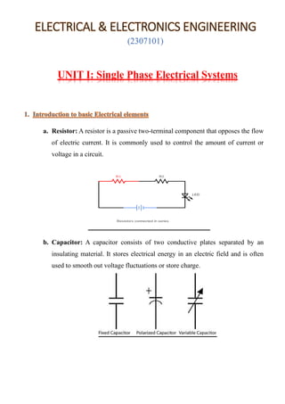
  • 1. ELECTRICAL & ELECTRONICS ENGINEERING (2307101) UNIT I: Single Phase Electrical Systems 1. a. Resistor: A resistor is a passive two-terminal component that opposes the flow of electric current. It is commonly used to control the amount of current or voltage in a circuit. b. Capacitor: A capacitor consists of two conductive plates separated by an insulating material. It stores electrical energy in an electric field and is often used to smooth out voltage fluctuations or store charge.
  • 2. c. Inductor: An inductor is a coil of wire that stores energy in a magnetic field when current flows through it. It resists changes in current and is used in applications like filtering and energy storage. d. Diode: A diode is a semiconductor device that allows current to flow in one direction only. It is commonly used for rectification (converting AC to DC), voltage regulation, and signal demodulation. e. Transistor: A transistor is a semiconductor device that can amplify or switch electronic signals and electrical power. It is a fundamental building block in modern electronics.
  • 3. f. Voltage Source: A voltage source provides a specific voltage level across its terminals, either as a constant value (DC) or as an alternating value (AC). g. Current Source: A current source provides a specific current level through its terminals. It can also be either constant (DC) or alternating (AC). h. Battery: A battery is a device that stores chemical energy and converts it into electrical energy. It's commonly used as a portable DC voltage source. i. Ground: In electronics, ground serves as a reference point for voltage measurements. It is often represented by a ground symbol and is used as a common point of reference in circuits. j. Switch: Aswitch is a device that can open or close an electrical circuit, allowing or interrupting the flow of current. It's used to control the state of a circuit.
  • 4. k. Fuse: A fuse is a safety device that protects a circuit from excessive current by breaking the circuit when the current exceeds a certain threshold. It helps prevent damage to components and possible fires. l. Circuit Breaker: Similar to a fuse, a circuit breaker is a safety device that automatically interrupts the circuit when there's an overload or short circuit. Unlike a fuse, it can be reset after tripping. m. Amplifier: An amplifier is a device that increases the amplitude of an electrical signal, making it larger. It's crucial in signal processing, audio systems, and communication devices.
  • 5. n. Transformer: A transformer is a device that transfers electrical energy between two or more circuits through electromagnetic induction. It's used to step up or step down AC voltages. o. Relay: A relay is an electrically operated switch that is controlled by a smaller electrical signal. It's often used to control larger currents or voltages with a smaller control signal. 2. ▪ Direct Current (DC): • Direct Current, often abbreviated as DC, is an electric current that flows in a single direction. • In a DC circuit, the voltage remains constant over time, and the flow of electric charge is unidirectional. • Batteries and most electronic devices, like cell phones and laptops, operate on DC power.
  • 6. ▪ Alternating Current (AC): • Alternating Current, abbreviated as AC, is an electric current that changes direction periodically. • The voltage and current in an AC circuit oscillate in a sinusoidal waveform. AC is the type of electricity that is delivered to homes and businesses through power lines. • It's used for its ability to be easily transformed into different voltage levels, making long-distance power transmission more efficient. Some key differences between AC and DC: 1. Direction of Current: o DC: The electric current flows in a constant direction. o AC: The electric current changes direction periodically, typically in a sinusoidal waveform. 2. Voltage Polarity: o DC: The voltage remains constant in terms of polarity. o AC: The voltage changes polarity periodically as the current direction changes. 3. Energy Transfer: o DC: Transfers energy steadily and uniformly. o AC: Transfers energy in cycles, alternating between positive and negative values. 4. Power Transmission: o DC: Not as efficient for long-distance transmission due to energy losses over distance. o AC: More efficient for long-distance transmission due to the ability to change voltage levels using transformers. 5. Applications: o DC: Often used in electronic devices and batteries.
  • 7. o AC: Used for power distribution, lighting, motors, and most household appliances. 6. Generation: o DC: Can be generated using batteries, solar cells, and rectifiers. o AC: Generated by alternators and generators. 7. Conversion: o DC: Can be converted into AC using inverters. o AC: Can be converted into DC using rectifiers. 3. A. • A series AC circuit is a circuit configuration where components like resistors, inductors, and capacitors are connected one after the other along a single path through which alternating current (AC) flows. • This type of circuit is characterized by the fact that the same current flows through all components in the circuit. ➢ Key Characteristics: ▪ Current: In a series circuit, the current (I) remains constant throughout the circuit. Since there is only one path for the current to flow, it must be the same for all components.
  • 8. ▪ Voltage: The total voltage (V_total) across the series circuit is the sum of the individual voltage drops across each component. This is in accordance with Kirchhoff's voltage law (KVL). ▪ Impedance: In an AC circuit, each component (resistor, inductor, capacitor) has an impedance (Z) that includes both magnitude and phase. The total impedance of the series circuit (Z_total) is the algebraic sum of the individual impedances. ▪ Phasor Diagrams: Phasor diagrams are used to represent the relationships between current and voltage in components like inductors and capacitors. These diagrams help visualize phase differences. ▪ Resonance: Series AC circuits can exhibit resonance when the inductive reactance (XL) equals the capacitive reactance (XC). At this point, the impedance becomes purely resistive, and the circuit is resonant.
  • 9. B. Parallel AC circuits are a type of electrical circuit configuration in which multiple components or branches are connected in parallel across the same voltage source. In a parallel AC circuit, each component or branch has the same voltage across its terminals, but the current flowing through each branch can vary independently. 4. Ohm's Law is a fundamental principle in electricity and electronics that describes the relationship between voltage, current, and resistance in an electric circuit.
  • 10. 5. Impedance in AC circuits is an extension of resistance in DC circuits. It is a complex quantity that incorporates both the resistance and reactance (which accounts for phase shifts due to inductive and capacitive elements) of a component in an alternating current (AC) circuit. Impedance is denoted by the symbol Z and is measured in ohms (Ω).
  • 11.
  • 12. 6. A. KIRCHOFFS CURRENT LAW KCL is named after Gustav Kirchhoff, a German physicist who formulated these laws in the mid-19th century. KCL states: "The algebraic sum of currents entering a junction (or node) in an electrical circuit is equal to the algebraic sum of currents leaving the junction." In simpler terms, KCL means that the total current flowing into a junction or node in an electrical circuit must equal the total current flowing out of that junction or node. This law is based on the principle of conservation of electric charge, which states that electric charge is neither created nor destroyed within a closed system; it can only flow from one point to another. Mathematically, KCL can be expressed as follows: ΣI _in = ΣI _out Where: - ΣI _in represents the algebraic sum of currents entering the node. - ΣI _out represents the algebraic sum of currents leaving the node. Fig 1: Node with four Conductors
  • 13. NUMERICALS ON KCL **Example 1:** Simple Series Circuit 1. Consider a simple series circuit with three resistors connected in series to a 12-volt voltage source. The resistors have values of 4 ohms, 6 ohms, and 8 ohms. We want to find the current through each resistor using KCL. 1. First, apply KCL at the single node in the circuit, which is where all the currents meet (the point where the resistors are connected in series). **ΣI_in = ΣI_out** Since this is a series circuit, the current is the same through all resistors. Let's call this common current "I." 2. Using Ohm's law (V = IR), calculate the current "I" for each resistor: For the 4-ohm resistor: I = V / R = 12 V / 4 ohms = 3 A For the 6-ohm resistor: I = V / R = 12 V / 6 ohms = 2 A For the 8-ohm resistor: I = V / R = 12 V / 8 ohms = 1.5 A So, in this circuit, the current through the 4-ohm resistor is 3 A, the current through the 6-ohm resistor is 2 A, and the current through the 8-ohm resistor is 1.5 A.
  • 14. **Example 2:** Parallel Circuit Now, let's consider a parallel circuit with three resistors connected in parallel to a 24-volt voltage source. The resistors have values of 2 ohms, 4 ohms, and 6 ohms. We want to find the total current supplied by the voltage source and the current through each resistor using KCL. 1. Apply KCL at the junction point (node) where all the currents meet: **ΣI_in = ΣI_out** In a parallel circuit, the total current supplied by the voltage source is equal to the sum of the currents through each branch. Let's call the total current "I_total." 2. Using Ohm's law (V = IR), calculate the current for each resistor: For the 2-ohm resistor: I_2ohm = V / R = 24 V / 2 ohms = 12 A For the 4-ohm resistor: I_4ohm = V / R = 24 V / 4 ohms = 6 A For the 6-ohm resistor: I_6ohm = V / R = 24 V / 6 ohms = 4 A 3. Calculate the total current: I_total = I_2ohm + I_4ohm + I_6ohm I_total = 12 A + 6 A + 4 A = 22 A So, in this parallel circuit, the total current supplied by the voltage source is 22 A, the current through the 2-ohm resistor is 12 A, the current through the 4-ohm resistor is 6 A, and the current through the 6-ohm resistor is 4 A. B. KIRCHOFFS VOLTAGE LAW KVL deals with the conservation of energy in electrical circuits and is essential for analysing circuit behaviour. KVL states: "The sum of voltage rises around any loop equals the sum of voltage drops" OR “The algebraic sum of all voltages around any loop equals zero”
  • 15. Mathematically, KVL can be expressed as follows: ΣV_drop = ΣV_source Where: - ΣV_drop represents the algebraic sum of voltage drops (changes in electric potential) encountered as you travel around a closed loop in the circuit. - ΣV_source represents the algebraic sum of electromotive forces (emf) or voltage sources encountered as you travel around the same closed loop. Fig 2: Closed Circuit According to KVL, the voltage equation can be written as, -Vs +V1 +V2 = 0 Vs = V1 + V2 ∑ Vrises = ∑ Vfall
  • 16. **Example 1:** Simple Series Circuit with Two Resistors Consider a simple series circuit consisting of a 9-volt battery and two resistors connected in series. The resistors have values of 3 ohms and 6 ohms. We want to find the voltage drop across each resistor and the total voltage supplied by the battery using KVL. 1. Apply KVL to the closed loop formed by the battery and the two resistors. We'll assume that the current flows in a clockwise direction in the loop. **ΣV_drop = ΣV_source** In this case, there is only one voltage source, which is the 9-volt battery, and two voltage drops across the resistors. Let's denote the voltage drop across the 3-ohm resistor as V_3ohm and the voltage drop across the 6-ohm resistor as V_6ohm. KVL equation: V_source - V_3ohm - V_6ohm = 0 2. Determine the voltage drop across each resistor using Ohm's law (V = IR): For the 3-ohm resistor: V_3ohm = I * R = I * 3 ohms For the 6-ohm resistor: V_6ohm = I * R = I * 6 ohms
  • 17. 3. Now, express the voltage drops in terms of current "I": V_3ohm = 3I (since R = 3 ohms) V_6ohm = 6I (since R = 6 ohms) 4. Substitute these expressions into the KVL equation: 9V - 3I - 6I = 0 5. Simplify the equation: 9V - 9I = 0 6. Now, solve for the current "I": 9I = 9V I = 9V / 9 I = 1 A 7. With the current "I" known, you can calculate the voltage drops across each resistor: V_3ohm = 3I = 3 * 1 A = 3 V V_6ohm = 6I = 6 * 1 A = 6 V So, in this series circuit: - The current flowing through the circuit is 1 ampere (1 A). - The voltage drop across the 3-ohm resistor is 3 volts. - The voltage drop across the 6-ohm resistor is 6 volts.
  • 18. - The total voltage supplied by the 9-volt battery is distributed across the resistors, with 3 volts dropped across the 3-ohm resistor and 6 volts dropped across the 6- ohm resistor, consistent with KVL. **Example 2:** Simple Series Circuit with Three Resistors 7. Series RLC Circuit: Analysis and Example Problems Consider the circuit consisting of R, L and C connected in series across a supply voltage of V (RMS) volts. The resulting current I (RMS) is flowing in the circuit. Since the R, L and C are connected in series, thus current is same through all the three elements. For the convenience of the analysis, the current can be taken as reference phasor. Therefore,
  • 19. Voltage across R, VR=IR Voltage across L,VL=IXL Voltage across C,VC=IXc Where, • XL = jωL = Inductive Reactance, • Xc = 1/jωC = Capacitive reactance. • VR is in phase with I. • VL is leading the current I by 90°. • VC is lagging the I by 90° The total voltage is the phasor sum of VR, VL and VC, i.e., V=VR+VL+VC Three cases of series RLC circuit Case 1 – When XL > XC, in this case the circuit is said to be inductive causing current to lag the applied emf. The phase angle between current (I) and emf (V) is positive, indicates that current lags behind the voltage.
  • 20. Case 2 – When XC > XL, in this case the circuit is said to be capacitive, causing current to lead the applied emf. The phase angle between current (I) and emf (V) is negative, indicates that current leads the voltage. Case 3 – When XC = XL, thus, the phase angle φ is zero, so the circuit acts as a purely resistive circuit and has unity power factor.
  • 21. Numerical : A 240 V, 50 Hz AC supply is applied a coil of 0.08 H inductance and 4 Ω resistance connected in series with a capacitor of 8 μF. Calculate the following − • Impedance, • Circuit current, • Phase angle between voltage and current, • Power factor, • Power consumed, • Q-factor of the circuit at resonant frequency. Solution: Here consider value of C = 8x10⁻⁶ • Impedance of the circuit
  • 22. • Circuit current • Phase angle between voltage and current The negative sing of phase angle shows that current is leading the voltage. • Power Factor • Power consumed • Q-factor of circuit at series resonance Power Factor Basics The term "leading" or "lagging" is used to describe the relationship between the current and voltage waveforms in an AC circuit, which, in turn, determines the power factor. 1. Leading Power Factor: - Definition: A leading power factor occurs when the current waveform leads the voltage waveform in phase. In other words, the current reaches its peak ahead of the voltage.
  • 23. - Cause:Leading power factors are typically associated with capacitive loads, such as capacitors. In a capacitive circuit, the current leads the voltage due to the energy storage and discharge characteristics of the capacitor. - Effect on Power Factor:A leading power factor is considered to be positive, and it improves the overall power factor of the system. 2. Lagging Power Factor: - Definition: A lagging power factor occurs when the current waveform lags behind the voltage waveform in phase. In this case, the voltage reaches its peak ahead of the current. - Cause: Lagging power factors are associated with inductive loads, such as motors and transformers. In an inductive circuit, the current lags behind the voltage due to the time required to establish the magnetic field. - Effect on Power Factor: A lagging power factor is considered to be negative. It tends to reduce the overall power factor of the system. 3. Unity Power Factor: - Definition:Unity power factor occurs when the current and voltage waveforms are perfectly in phase, i.e., they peak and trough at the same time. - Cause: Unity power factor is typically associated with purely resistive loads. In these cases, the current and voltage are in phase because there are no reactive components (inductance or capacitance) in the circuit. - Effect on Power Factor: Unity power factor is considered ideal, as it indicates that all the power is being used effectively. Power factor is a crucial parameter in AC circuits, especially in industrial settings, as it affects the efficiency of the electrical system and can result in higher energy costs. It's important to design and operate systems to maintain a power factor as close to unity as possible to maximize efficiency. PURE R, PURE L and PURE C AC Circuits:
  • 24.
  • 25.
  • 26. 7.2 Parallel RLC Circuits
  • 27. A Parallel RLC circuit is a type of electrical circuit that contains resistors (R), inductors (L), and capacitors (C) connected in parallel across a voltage source. This configuration allows for the combination of the individual impedance characteristics of these components. 1.Resistor (R): • Offers resistance to the flow of current. • The impedance of a resistor is purely real and is given by ZR=R. • In a parallel RLC circuit, the resistor remains constant across all frequencies. 2. Inductor (L): • Induces a voltage proportional to the rate of change of current flowing through it (Faraday's law of electromagnetic induction). • The impedance of an inductor is given by ZL where j is the imaginary unit, ω is the angular frequency (2πf), and L is the inductance in Henries. • At low frequencies, inductors offer high impedance, and at high frequencies, they offer low impedance. 3. Capacitor (C): • Stores and releases electrical energy in response to changes in voltage. • The impedance of a capacitor is given by where j is the imaginary unit, ω is the angular frequency, and C is the capacitance in farads. • At low frequencies, capacitors offer low impedance, and at high frequencies, they offer high impedance.
  • 28. In a parallel RLC circuit, the total impedance Z total is the reciprocal of the sum of the reciprocals of individual component impedances: The resonant frequency fres of the circuit is the frequency at which the inductive and capacitive reactance’s cancel each other out, resulting in a purely resistive impedance. It is given by: Where: - fres is the resonant frequency in hertz (Hz). - L is the inductance in henries (H). - C is the capacitance in farads (F). At resonance, the total impedance is equal to the resistance (Ztotal=R) Pl Note: Some more numericals on RLC will be included in final copy.
  • 29.
  • 30.
  • 31. ▪ Here are some typical power ratings for common home appliances: 1. Fan: - Ceiling Fan: 60-75 watts - Table Fan: 40-60 watts - Exhaust Fan: 20-40 watts 2. Tube Light (Fluorescent): 40 watts (for a standard 4-foot tube light) 3. Incandescent Bulb: 40-100 watts (depending on the brightness) 4. LED Bulb: 4-15 watts (depending on brightness and type) 5. Refrigerator: 100-800 watts (varies by size, age, and efficiency) 6. Air Conditioner (Window Unit): 1000-2500 watts (depends on capacity) 7. Air Conditioner (Split Unit): 900-3500 watts (depends on capacity) 8. Washing Machine: 300-500 watts (varies by type and capacity) 9. Microwave Oven: 600-1500 watts (depends on power level and type) 10. Mixer/Grinder: 300-1000 watts (depends on motor power) 11. Iron: 1000-1800 watts 12. Vacuum Cleaner: 500-1500 watts
  • 32. 13. Laptop/Computer: 20-300 watts (depends on model and usage) 14. Television: - LED/LCD TVs: 30-400 watts (depends on size and type) - Plasma TVs: 100-500 watts 15. Hair Dryer: 800-1800 watts 16. Water Heater (Electric): 1500-4500 watts (depends on capacity) 17. Induction Cooktop: 1000-2000 watts 18. Toaster: 800-1800 watts 19. Electric Kettle: 1000-1500 watts 20. Dishwasher: 1200-1500 watts It's important to note that these are approximate power ratings and can vary based on the specific make, model, and brand of the appliance. Additionally, some appliances may have multiple power settings or modes, which can affect their energy consumption. Understanding the power ratings of these appliances is crucial for designing electrical systems in homes, calculating energy consumption, and making informed decisions about energy efficiency. This knowledge is particularly relevant for electrical engineering students as it forms the basis for more advanced studies in power systems and energy management.
  • 33. Numerical on calculating power ratings of home appliances. 1. Example 1: Ceiling Fan A ceiling fan operates at a voltage of 220 volts (V) and draws a current of 0.5 amperes (A). Using the formula P = V X I, the power rating of the ceiling fan is: P = 220 V X 0.5 A = 110 W Therefore, the power rating of the ceiling fan is 110 watts. 2. Example 2: Refrigerator Suppose a refrigerator operates at a voltage of 120 volts (V) and draws a current of 5 amperes (A). Using the same formula, the power rating of the refrigerator is: P = 120 V X 5 A = 600 W So, the power rating of the refrigerator is 600 watts. 3. Example 3: Microwave Oven Consider a microwave oven that operates at a voltage of 230 volts (V) and draws a current of 10 amperes (A). Using the formula, the power rating of the microwave oven is: P = 230 V X10 A = 2300 W The power rating of the microwave oven is 2300 watts. 4. Example 4: Desktop Computers
  • 34. Let's consider a desktop computer: - Voltage (V): 120 volts - Current (I): 3 amperes Using the formula P = V X I, we can find the power consumption: P = 120 V X 3 A = 360 W So, the power rating of this hypothetical desktop computer is 360 watts. 5. Example 5: AC Motor To calculate power ratings for an AC motor. Let's assume we have an AC motor with the following specifications: - Voltage (V) = 230 volts - Current (I) = 5 amperes - Power Factor (PF) = 0.85 (Typical value for many AC motors) Using the formula for power in an AC circuit: P = V X I X PF P = 230 V X 5 A X 0.85 = 977.5 W So, the power rating of this AC motor is approximately 977.5 watts or 0.9775 kilowatts (kW). Note: Keep in mind that the power factor (PF) is a dimensionless number between 0 and 1 that represents the efficiency with which the motor converts electrical power into mechanical power. In practice, power factor values are typically between 0.8 and 0.9 for many AC motors. . ▪
  • 35. 1. Single-Phase and Three-Phase Supply: - Understanding the difference between single-phase and three-phase electrical supply. - Recognizing where each type of supply is typically used (e.g., single- phase for residential buildings, three-phase for industrial applications). 2. Service Connection: - Learning about the service entrance, which is the point where electrical power is supplied to the house from the utility company. - Understanding the components of a service connection, such as the service drop, meter, and main disconnect. 3. Distribution Board (DB) / Consumer Unit: - Studying the distribution board or consumer unit, which is a panel that distributes electrical power to various circuits within the house. - Learning about the main switch, circuit breakers, and residual current devices (RCDs) for safety. 4. Circuit Wiring: - Understanding how circuits are wired in a residential building, including lighting circuits and power circuits. - Differentiating between radial and ring circuits. 5. Wire Sizing and Types: - Learning how to select the appropriate wire size based on the load and length of the circuit. - Familiarizing with different types of wires (e.g., copper, aluminium) and their applications. 6. Switches and Outlets: - Understanding the different types of switches (e.g., single-pole, double- pole, three-way) and outlets (e.g., single, double, socket outlets). - Learning about the wiring configurations for switches and outlets.
  • 36. 7. Grounding and Earthing: - Studying the importance of grounding and earthing for electrical safety. - Understanding how grounding rods and conductors are installed. 8. Safety Considerations: - Emphasizing safety practices when working with electricity, including using personal protective equipment (PPE) and following proper procedures. 9. Regulations and Codes: - Familiarizing with local electrical codes and regulations that govern residential electrical installations. 10. Load Calculation: - Learning how to calculate the total load of a house to ensure that the electrical system can handle the connected appliances and devices. 11. Troubleshooting and Maintenance: - Developing skills in identifying and resolving common electrical issues in a residential setting. - Understanding the importance of regular maintenance and inspections. A simple circuit diagram for the electrical connection of a house: The diagram typically includes the main components like the service entrance, distribution board, and various loads. Here's a basic illustration:
  • 37. __________________________ | Service | | Entrance | | (Meter) | |__________________________| | | | | | | | | ____ | |____ | | | | ____ ____ | DB | | DB | |____| |____| | | | | ____| |____ ____| |____ | | | | | | | | | | | | | | | | | | | | | | | | |________| |__________________| |__| Load 1 Load 2 Load 3 Load 4 (e.g., Light) (e.g., Fan) (e.g., Socket) (e.g., Heater) In this diagram: 1. Service Entrance (Meter): This is where the electrical power from the utility company enters the house. It includes a meter to measure the amount of electricity consumed. 2. Distribution Board (DB) / Consumer Unit: This is a panel that distributes electrical power to various circuits within the house. It contains circuit breakers or fuses to protect the circuits from overloading.
  • 38. 3. Loads: These are the devices or appliances connected to the electrical system. Loads can include lights, fans, sockets, heaters, and other appliances. 4. Wiring: The wiring connects the loads to the distribution board and ensures the flow of electricity. Keep in mind that this is a simplified representation. In a real house, there would be multiple circuits serving different areas and types of loads. Additionally, safety features like grounding, earthing, and protective devices would be incorporated. 1.Switch operated Tube light 2.Switch operated fan and regulator 3.Switch operated lightning systems in functions. ▪ Fuse, MCBs and Grounding for safety at home: Fuse, Miniature Circuit Breakers (MCBs), and grounding are crucial safety components in any electrical system, including homes. They play key roles in preventing electrical hazards and protecting both people and property. Here's an overview of each: 1. Fuse: - Function: A fuse is a safety device that protects an electrical circuit by interrupting the flow of current when it exceeds a specified amperage. It does this by melting a wire element inside the fuse when excessive current flows through it. - Operation: When the current exceeds the rated value, the wire inside the fuse melts, breaking the circuit and preventing further damage or a potential fire. - Advantages: - Inexpensive and easy to replace. - Provides effective protection against short circuits and overloads.
  • 39. - Considerations: - Fuses need to be replaced after they have blown. - The correct type and rating of fuse must be used for each circuit. 2. Miniature Circuit Breakers (MCBs): - Function: MCBs perform a similar function to fuses, but they are reusable. The automatically breaks the circuit when an overload or short circuit occurs. - Operation: When an abnormal current flows through the circuit, the MCB trips (opens the circuit) to protect against overheating or fire. It can be reset once the fault is corrected. - Advantages: - More convenient as they can be easily reset after a trip. - Provide a higher degree of precision in terms of tripping thresholds. - Considerations: - MCBs need to be properly sized for the circuit they protect. - They should be of the correct type (e.g., B-type for general circuits, C- type for motor loads).
  • 40. 3. Grounding: - Function: Grounding provides a safe path for excess electrical current to dissipate into the earth. It helps prevent electric shock, fire, and equipment damage. - Operation: In a grounded system, electrical equipment is connected to a grounding electrode (usually a metal rod driven into the earth). This allows any excess current to safely dissipate. - Advantages: - Enhances safety by minimizing the risk of electric shock. - Helps protect against lightning strikes and static discharge. - Considerations: - Proper installation and maintenance of grounding systems are crucial for their effectiveness. - Grounding should meet local electrical codes and standards.
  • 41. NUMERICALS ON FUSE Example 1: Fuse Rating Calculation: Suppose you have a circuit with the following specifications: Maximum allowable current (I_max) = 15 Amperes (A), Voltage (V) = 230 Volts (V). Select an appropriate fuse for this circuit. Solution: To find the appropriate fuse rating, we use the formula: P = V X I_max where P is the power in watts (W), V is the voltage in volts (V), and I is the current in amperes (A). Given the voltage and maximum allowable current, we can calculate the maximum power: P= V X I_max = 230V X15A = 3450 W So, you would select a fuse with a rating slightly higher than 3450 Watts, which might be a standard value like 3500 Watts. Example 2: Fuse Replacement Suppose you have a 10Afuse in a circuit, and it has blown due to an overload. You replace it with a 15A fuse because you don't have a 10A fuse on hand. Solution: This is not a recommended practice. The 10A fuse was installed for a reason - it was chosen to protect the circuit from currents exceeding 10A. By replacing it with a 15A fuse, you're allowing a higher current to flow through the circuit, which could lead to overheating and potential hazards.
  • 42. Always use the correct rated fuse for a circuit. If you don't have the right replacement fuse, it's better to wait until you can get the correct one rather than using a higher-rated fuse.
  • 43. ELECTRICAL & ELECTRONICS ENGINEERING (2307101) UNIT II: Three Phase Electrical Systems 1. A three-phase system is a method of generating, transmitting, and distributing electrical power. It's a type of polyphase system, meaning it uses multiple alternating currents (AC) that are out of phase with each other. Three-phase systems are widely used in various applications due to their efficiency, especially in industrial and commercial settings. Here are the key components and concepts of a three-phase system: 1. Phases: - A three-phase system consists of three separate AC voltages or currents that are 120 degrees out of phase with each other. These are typically labelled as Phase A, Phase B, and Phase C. - Each phase has its own sine wave, and together they form a balanced system. 2. Phase Sequence: - The order in which the phases cycle is known as the phase sequence. It can be either clockwise (positive sequence), counter-clockwise (negative sequence), or a combination of both (zero sequence). 3. Phase Angle: - The angular displacement between phases is 120 degrees in a balanced three-phase system. This creates a smooth and continuous flow of power.
  • 44. 4. Generation: - In power generation, three-phase systems are commonly used to produce electricity. Most power plants generate three-phase AC, and this form is preferred for its efficiency and ability to handle heavy loads. 5. Advantages: - Efficiency: Three-phase systems are more efficient for transmitting and distributing power over long distances compared to single-phase systems. - Balanced Loads: They allow for balanced loads across the phases, reducing the need for larger, costly equipment. - Motor Performance: Three-phase motors are widely used in industrial applications due to their high efficiency and smooth operation. 6. Applications: - Industrial Machinery: Three-phase power is used to operate heavy machinery, pumps, compressors, and other industrial equipment. - Commercial Buildings: Many commercial buildings receive three-phase power for elevators, air conditioning, and other large systems. - Power Distribution: It's used extensively in power distribution networks to efficiently deliver electricity to homes and businesses. 7. Delta and Wye (Star) Connections: - These are two common configurations for connecting three-phase systems. - Delta Connection: In this setup, the windings of the generator or transformer are connected in the shape of a delta (Δ). - Wye (Star) Connection: Here, the windings are connected in a Y shape.
  • 45. 8. Colour Codes: - Different regions have specific colour codes for identifying the different phases. For instance, in the US, Phase A is often black, Phase B is red, and Phase C is blue. 9. Transformers: - Transformers are used to step up or step down the voltage in a three-phase system for transmission or distribution. 10. Unbalanced Systems: - In practical situations, the loads on the three phases may not be exactly equal, resulting in an unbalanced system. This can lead to issues like voltage drop and motor overheating.
  • 46.
  • 47. 2. Delta and Star connections are two common configurations used in three-phase electrical systems to connect loads, generators, and transformers. They determine how the three phases are connected together. Let's explore each connection: Delta Connection (Δ): - In a delta configuration, the windings of the generator or transformer are connected in the shape of a triangle or delta symbol (Δ). - Each end of the winding is connected to one of the phases, and the three-phase outputs are taken from the three remaining connections. - In a delta system, the line voltage is equal to the phase voltage. However, the line current is √3 times the phase current. - This connection is commonly used in industrial settings and for power transmission.
  • 48. - Delta connections are preferred in situations where the load is mostly balanced. - The delta configuration is known for its robustness and ability to handle unbalanced loads. - Delta-connected systems do not have a neutral wire. Star Connection (Y or Wye): - In a star configuration, the windings of the generator or transformer are connected in the shape of a star or letter "Y". - One end of each winding is connected together at a central point, called the neutral. The three-phase outputs are then taken from the other ends of the windings. - In a star system, the line current is equal to the phase current, but the line voltage is √3 times the phase voltage. - Star connections are commonly used in residential and commercial buildings. - The star configuration provides a neutral wire, which is important for distributing single-phase power to devices. - It is suitable for situations where the loads are likely to be unbalanced. - Star-connected systems are generally more flexible for handling single-phase loads. Comparison: - Delta systems are more robust and better for handling unbalanced loads, making them suitable for industrial applications. - Star systems are more common in residential and commercial settings due to their ability to provide a neutral wire and handle single-phase loads. - Delta systems have higher line currents, which can lead to higher losses in the distribution system. - Star systems are more flexible for distributing single-phase power and are often used in situations where loads may vary.
  • 49. - In practice, the choice between delta and star connections depends on factors like the type of load, the level of balancing, and the specific requirements of the application. Both delta and star connections have their own advantages and are used in different contexts based on the specific needs of the electrical system. Understanding these configurations is crucial for designing and operating efficient three-phase systems. Star (Y) Connection Delta (Δ) Connection In STAR connection, the starting or finishing ends (Similar ends) of three coils are connected together to form the neutral point. A common wire is taken out from the neutral point which is called Neutral. In DELTA connection, the opposite ends of three coils are connected together. In other words, the end of each coil is connected with the start of another coil, and three wires are taken out from the coil joints There is a Neutral or Star Point No Neutral Point in Delta Connection Three phase four wire system is derived from Star Connections (3-Phase, 4 Wires System) We may Also derived 3 Phase 3 Wire System from Star Connection Three phase three wire system is derived from Delta Connections (3-Phase, 3 Wires System) Line Voltage is √3 times of Phase Voltage. i.e. VL = √3 VPH Line Voltage is Equal to Phase Voltage. i.e. VL = VPH Line Current is Equal to Phase Current. IL = IPH Line Current is √3 times of Phase Current. i.e. IL = √3 IPH The Total Power of three phases could be found by W = √3 x VL x IL x CosФ OR W = 3 x VPH x IPH x CosФ The Total Power of three phases could be found by W = √3 x VL x IL x CosФ OR W = 3 x VPH x IPH x CosФ The speeds of Star connected motors are slow as they receive 1/√3 voltage. The speeds of Delta connected motors are high because each phase gets the total of line voltage
  • 50. In Star Connection, the phase voltage is low as 1/√3 of the line voltage, so, it needs low number of turns, hence, saving in copper. In Delta connection, The phase voltage is equal to the line voltage, hence, it needs more number of turns. Low insulation required as phase voltage is low Heavy insulation required as Phase voltage = Line Voltage. In Power Distribution and industries, Star Connection system is general to be used. In Power Transmission, Delta Connection is general to be used.
  • 51.
  • 52.
  • 53.
  • 54.
  • 55.
  • 56.
  • 57.
  • 58.
  • 59.
  • 60. SINGLE PHASE TRANSFORMERS Transformer Basics: One of the main reasons that we use alternating AC voltages and currents in our homes and workplace’s is that AC supplies can be easily generated at a convenient voltage, transformed (hence the name transformer) into much higher voltages and then distributed around the country using a national grid of pylons and cables over very long distances. The reason for transforming the voltage to a much higher level is that higher distribution voltages implies lower currents for the same power and therefore lower I2 *R losses along the networked grid of cables. These higher AC transmission voltages and currents can then be reduced to a much lower, safer and usable voltage level where it can be used to supply electrical equipment in our homes and workplaces, and all this is possible thanks to the transformer basics of the Voltage Transformer. The Voltage Transformer can be thought of as an electrical component rather than an electronic component. A transformer basically is very simple static (or stationary) electro-magnetic passive electrical device that works on the principle of Faraday’s law of induction by converting electrical energy from one value to another. The transformer does this by linking together two or more electrical circuits using a common oscillating magnetic circuit which is produced by the transformer itself. A transformer basics operate on the principals of “electromagnetic induction”, in the form of Mutual Induction. Mutual induction is the process by which a coil of wire magnetically induces a voltage into another coil located in close proximity to it. Then we can say that transformers work in the “magnetic domain”, and transformers get their name from the fact that they “transform” one voltage or current level into another.
  • 61. Transformers are capable of either increasing or decreasing the voltage and current levels of their supply, without modifying its frequency, or the amount of electrical power being transferred from one winding to another via the magnetic circuit. A single phase voltage transformer basically consists of two electrical coils of wire, one called the “Primary Winding” and another called the “Secondary Winding”. For this tutorial we will define the “primary” side of the transformer as the side that usually takes power, and the “secondary” as the side that usually delivers power. In a single-phase voltage transformer the primary is usually the side with the higher voltage. These two coils are not in electrical contact with each other but are instead wrapped together around a common closed magnetic iron circuit called the “core”. This soft iron core is not solid but made up of individual laminations connected together to help reduce the core’s magnetic losses. The primary and secondary windings are electrically isolated from each other but are magnetically linked through the common core allowing electrical power to be transferred from one coil to the other. When an electric current passed through the primary winding, a magnetic field is developed which induces a voltage into the secondary winding and this transformer basics operating principle shown below.
  • 62. Transformer Construction (single-phase) • Where: • VP – is the Primary Voltage • VS – is the Secondary Voltage • NP – is the Number of Primary Windings • NS – is the Number of Secondary Windings • Φ (phi) – is the Flux Linkage Notice that the two coil windings are not electrically connected but are only linked magnetically. A single-phase transformer can operate to either increase or decrease the voltage applied to the primary winding. When a transformer is used to “increase” the voltage on its secondary winding with respect to the primary, it is called a Step-up transformer. When it is used to “decrease” the voltage on the secondary winding with respect to the primary it is called a Step- down transformer.
  • 63. However, a third condition exists in which a transformer produces the same voltage on its secondary as is applied to its primary winding. In other words, its output is identical with respect to voltage, current and power transferred. This type of transformer is called an “Impedance Transformer” and is mainly used for impedance matching or the isolation of adjoining electrical circuits. The difference in voltage between the primary and the secondary windings is achieved by changing the number of coil turns in the primary winding ( NP ) compared to the number of coil turns on the secondary winding ( NS ). As the transformer is basically a linear device, a ratio now exists between the number of turns of the primary coil divided by the number of turns of the secondary coil. This ratio, called the ratio of transformation, more commonly known as a transformers “turns ratio”, ( TR ). This turns ratio value dictates the operation of the transformer and the corresponding voltage available on the secondary winding. It is necessary to know the ratio of the number of turns of wire on the primary winding compared to the secondary winding. The turns ratio, which has no units, compares the two windings in order and is written with a colon, such as 3:1 (3- to-1). This means in this example, that if there are 3 volts on the primary winding there will be 1 volt on the secondary winding, 3 volts-to-1 volt. Then we can see that if the ratio between the number of turns changes the resulting voltages must also change by the same ratio, and this is true. Transformers are all about “ratios”. The ratio of the primary to the secondary, the ratio of the input to the output, and the turns ratio of any given transformer will be the same as its voltage ratio. In other words for a transformer: “turns ratio = voltage ratio”. The actual number of turns of wire on any winding is generally not important, just the turns ratio and this relationship is given as: A Transformers Turns Ratio Assuming an ideal transformer and the phase angles: ΦP ≡ ΦS Note that the order of the numbers when expressing a transformers turns ratio value is very important as the turns ratio 3:1 expresses a very different
  • 64. transformer relationship and output voltage than one in which the turns ratio is given as: 1:3. Types Of Transformers Transformers can be classified on different basis, like types of construction, types of cooling etc. (A) On the basis of construction, transformers can be classified into two types as; (i) Core type transformer and (ii) Shell type transformer, which are described below. (I) Core Type Transformer In core type transformer, windings are cylindrical former wound, mounted on the core limbs as shown in the figure above. The cylindrical coils have different layers and each layer is insulated from each other. Materials like paper, cloth or mica can be used for insulation. Low voltage windings are placed nearer to the core, as they are easier to insulate. (Ii) Shell Type Transformer The coils are former wound and mounted in layers stacked with insulation between them. A shell type transformer may have simple rectangular form (as shown in above fig), or it may have a distributed form. (B) On the basis of their purpose 1. Step up transformer: Voltage increases (with subsequent decrease in current) at secondary. 2. Step down transformer: Voltage decreases (with subsequent increase in current) at secondary.
  • 65. (C) On the basis of type of supply 1. Single phase transformer 2. Three phase transformer (D) On the basis of their use 1. Power transformer: Used in transmission network, high rating 2. Distribution transformer: Used in distribution network, comparatively lower rating than that of power transformers. 3. Instrument transformer: Used in relay and protection purpose in different instruments in industries ▪ Current transformer (CT) ▪ Potential transformer (PT) (E) On the basis of cooling employed 1. Oil-filled self-cooled type 2. Oil-filled water cooled type 3. Air blast type (air cooled) Transformer Construction A simple two-winding transformer construction consists of each winding being wound on a separate soft iron limb or core which provides the necessary magnetic circuit A transformer construction provides a magnetic circuit, known more commonly as the “transformer core”, which is designed to provide a path for the magnetic field to flow around. This magnetic path is necessary for the induction of voltage between the two input and output windings.
  • 66. However, this type of transformer construction where the two windings are wound on separate limbs is not very efficient since the primary and secondary windings are well separated from each other. This results in a low magnetic coupling between the two windings as well as large amounts of magnetic flux leakage from the transformer itself. But as well as this “O” shapes construction, there are different types of “transformer construction” and designs available which are used to overcome these inefficiencies producing a smaller more compact transformer. The efficiency of a simple transformer construction can be improved by bringing the two windings within close contact with each other thereby improving the magnetic coupling. Increasing and concentrating the magnetic circuit around the coils may improve the magnetic coupling between the two windings, but it also has the effect of increasing the magnetic losses of the transformer core. As well as providing a low reluctance path for the magnetic field, the core is designed to prevent circulating electric currents within the iron core itself. Circulating currents, called “eddy currents”, cause heating and energy losses within the core decreasing the transformer’s efficiency. These losses are due mainly to voltages induced in the iron circuit, which is constantly being subjected to the alternating magnetic fields setup by the external sinusoidal supply voltage. One way to reduce these unwanted power losses is to construct the transformer core from thin steel laminations. In most types of transformer construction, the central iron core is constructed from of a highly permeable material commonly made from thin silicon steel laminations. These thin laminations are assembled together to provide the required magnetic path with the minimum of magnetic losses. The resistivity of
  • 67. the steel sheet itself is high, thus reducing any eddy current loss by making the laminations very thin. These steel transformer laminations vary in thickness’s from between 0.25mm to 0.5mm and as steel is a conductor, the laminations and any fixing studs, rivets or bolts are electrically insulated from each other by a very thin coating of insulating varnish or by the use of an oxide layer on the surface. Transformer Construction of the Core Generally, the name associated with the construction of a transformer is dependent upon how the primary and secondary windings are wound around the central laminated steel core. The two most common and basic designs of transformer construction are the Closed-core Transformer and the Shell-core Transformer. In the “closed-core” type (core form) transformer, the primary and secondary windings are wound outside and surround the core ring. In the “shell type” (shell form) transformer, the primary and secondary windings pass inside the steel magnetic circuit (core) which forms a shell around the windings as shown below. Transformer Core Construction In both types of transformer core design, the magnetic flux linking the primary and secondary windings travels entirely within the core with no loss of magnetic flux through air. In the core type transformer construction, one half of the winding is wrapped around each leg (or limb) of the transformer’s magnetic circuit as shown above.
  • 68. The coils are not arranged with the primary winding on one leg and the secondary on the other but instead half of the primary winding and half of the secondary winding are placed one over the other concentrically on each leg in order to increase magnetic coupling allowing practically all of the magnetic lines of force go through both the primary and secondary windings at the same time. However, with this type of transformer construction, a small percentage of the magnetic lines of force flow outside of the core, and this is called “leakage flux”. Shell type transformer core’s overcome this leakage flux as both the primary and secondary windings are wound on the same centre leg or limb which has twice the cross-sectional area of the two outer limbs. The advantage here is that the magnetic flux has two closed magnetic paths to flow around external to the coils on both left and right hand sides before returning back to the central coils. This means that the magnetic flux circulating around the outer limbs of this type of transformer construction is equal to Φ/2. As the magnetic flux has a closed path around the coils, this has the advantage of decreasing core losses and increasing overall efficiency. Transformer Laminations But you may be wondering as to how the primary and secondary windings are wound around these laminated iron or steel cores for this types of transformer constructions. The coils are firstly wound on a former which has a cylindrical, rectangular or oval type cross section to suit the construction of the laminated core. In both the shell and core type transformer constructions, in order to mount the coil windings, the individual laminations are stamped or punched out from larger steel sheets and formed into strips of thin steel resembling the letters “E”s, “L”s, “U”s and “I”s as shown below. Transformer Core Types
  • 69. These lamination stampings when connected together form the required core shape. For example, two “E” stampings plus two end closing “I” stampings to give an E-I core forming one element of a standard shell-type transformer core. These individual laminations are tightly butted together during it’s construction to reduce the reluctance of the air gap at the joints producing a highly saturated magnetic flux density. Transformer core laminations are usually stacked alternately to each other to produce an overlapping joint with more lamination pairs being added to make up the correct core thickness. This alternate stacking of the laminations also gives the transformer the advantage of reduced flux leakage and iron losses. E- I core laminated transformer construction is mostly used in isolation transformer’s, step-up and step-down transformer’s as well as the auto transformer. Transformer Winding Arrangements Transformer windings form another important part of a transformer construction, because they are the main current-carrying conductors wound around the laminated sections of the core. In a single-phase two winding transformer, two windings would be present as shown. The one which is connected to the voltage source and creates the magnetic flux called the primary winding, and the second winding called the secondary in which a voltage is induced as a result of mutual induction. If the secondary output voltage is less than that of the primary input voltage the transformer is known as a “Step-down Transformer”. If the secondary output voltage is greater than the primary input voltage it is called a “Step-up Transformer”.
  • 70. Core-type Construction The type of wire used as the main current carrying conductor in a transformer winding is either copper or aluminium. While aluminium wire is lighter and generally less expensive than copper wire, a larger cross sectional area of conductor must be used to carry the same amount of current as with copper so it is used mainly in larger power transformer applications. Small kVA power and voltage transformers used in low voltage electrical and electronic circuits tend to use copper conductors as these have a higher mechanical strength and smaller conductor size than equivalent aluminium types. The downside is that when complete with their core, these transformers can be much heavier. Transformer windings and coils can be broadly classified in to concentric coils and sandwiched coils. In core-type transformer construction, the windings are usually arranged concentrically around the core limb as shown above with the higher voltage primary winding being wound over the lower voltage secondary winding. Sandwiched or “pancake” coils consist of flat conductors wound in a spiral form and are so named due to the arrangement of conductors into discs. Alternate discs are made to spiral from outside towards the centre in an interleaved arrangement with individual coils being stacked together and separated by insulating materials such as paper of plastic sheet. Sandwich coils and windings are more common with shell type core construction. Transformer Core The insulation used to prevent the conductors shorting together in a transformer is usually a thin layer of varnish or enamel in an air cooled transformer. This thin varnish or enamel paint is painted onto the wire before it is wound around the core. In larger power and distribution type transformer’s, the conductors are insulated from each other using oil impregnated paper or cloth. The whole core and windings is immersed and sealed in a protective tank containing transformer oil. The transformer oil acts as an insulator and also as a coolant. Transformer Construction – Core Losses The ability of iron or steel to carry magnetic flux is much greater than it is in air, and this ability to allow magnetic flux to flow is called permeability. Most
  • 71. transformer cores are constructed from low carbon steels which can have a permeability in the order of 1500 compared with just 1.0 for air. This means that a steel laminated core can carry a magnetic flux 1500 times better than that of air. However, when a magnetic flux flows in the steel core of a transformer, two types of losses occur within the steel. One termed “eddy current losses” and the other one termed “hysteresis losses”. Hysteresis Losses Transformer Hysteresis Losses are caused because of the friction of the molecules against the flow of the magnetic lines of force required to magnetise the core, which are constantly changing in value and direction first in one direction and then the other due to the influence of the sinusoidal supply voltage. This molecular friction causes heat to be developed which represents an energy loss to the transformer. Excessive heat loss can overtime shorten the life of the insulating materials used in the manufacture of the windings and structures. Therefore, cooling of a transformer is important. Also, transformers are designed to operate at a particular supply frequency. Lowering the frequency of the supply will result in increased hysteresis and higher temperature in the iron core. So reducing the supply frequency from 60 Hertz to 50 Hertz will raise the amount of hysteresis present, decreased the VA capacity of the transformer. Eddy Current Losses Transformer Eddy Current Losses on the other hand are caused by the flow of circulating currents induced into the steel caused by the flow of the magnetic flux around the core. These circulating currents are generated because to the magnetic flux the core is acting like a single loop of wire. Since the iron core is a good conductor, the eddy currents induced by a solid iron core will be large. Eddy currents do not contribute anything towards the usefulness of the transformer but instead they oppose the flow of the induced current by acting like a negative force generating resistive heating and power loss within the core.
  • 72. Laminating the Iron Core Eddy current losses within a transformer core cannot be eliminated completely, but they can be greatly reduced and controlled by reducing the thickness of the steel core. Instead of having one big solid iron core as the magnetic core material of the transformer or coil, the magnetic path is split up into many thin pressed steel shapes called “laminations”. The laminations used in a transformer construction are very thin strips of insulated metal joined together to produce a solid but laminated core as we saw above. These laminations are insulated from each other by a coat of varnish or paper to increase the effective resistivity of the core thereby increasing the overall resistance to limit the flow of the eddy currents. The result of all this insulation is that the unwanted induced eddy current power-loss in the core is greatly reduced, and it is for this reason why the magnetic iron circuit of every transformer and other electro-magnetic machines are all laminated. Using laminations in a transformer construction reduces eddy current losses. Transformer Construction – Copper Losses The losses of energy, which appears as heat due both to hysteresis and to eddy currents in the magnetic path, is known commonly as “transformer core losses”. Since these losses occur in all magnetic materials as a result of alternating magnetic fields. Transformer core losses will always be present in a transformer whenever the primary winding is energized, even if there is no load connected to the secondary winding. Also, the combination of hysteresis and eddy current losses are commonly referred to as “transformer iron losses”, as the magnetic flux causing these losses is constant at all loads.
  • 73. Copper Losses But there is also another type of energy loss associated with the transformer called “copper losses”. Transformer Copper Losses are mainly due to the electrical resistance of the primary and secondary windings. Most transformer coils are wound using copper wire which has a resistive value in Ohms ( Ω ), and as we know from Ohms Law, the copper wire’s resistance will oppose any magnetising currents flowing through it. When an electrical load is connected to the secondary winding of a transformer, large electrical currents start to flow in both the primary and the secondary windings, electrical energy and power ( the I2 R ) losses occur as heat. Generally copper losses vary with the load current, being almost zero at no-load, and at a maximum at full-load when current flow is at maximum. A volt-amperes (VA) rating of a transformer can be increased by better design and construction in order to reduce these core and copper losses. A transformer with high voltage and current ratings require conductors of large cross-section to help minimise their copper losses. Increasing the rate of heat dissipation (better cooling) by forced air or oil, or by improving it’s insulation so that it can withstand higher temperatures, thereby increasing the VA rating of the transformer. Then we can define an ideal transformer as having: • No Hysteresis loops or Hysteresis losses → 0 • Infinite Resistivity of core material giving zero Eddy current losses → 0 • Zero winding resistance giving zero I2 *R copper losses → 0 In the next tutorial about Transformer’s we will look at Transformer Loading of the secondary winding with respect to an electrical load and see the effect a “NO-load” and a “ON-load” connected transformer has on the primary winding current.
  • 74. Transformer Action EMF Equation: Working Principle of a Transformer A transformer is made from a core that has common input and output sides. Two inductive windings are embedded in this core which is electrically insulated from each other. The input coil in which electrical voltage is fed is known as Primary Winding. The output coil from which the electrical voltage is drawn is called the Secondary Winding. You can check the detailed explanation video of how a transformer works. Transformer Construction and Winding When an input alternating voltage V1 is applied across the primary coil of the transformer, it generates an alternating current I1. An alternating electromotive force emf e1 is produced in the core. According to Faraday’s law of electromagnetic induction, An electromotive force emf e1 runs through the primary coil.
  • 75. Where, • EMF is a first-order time derivative of Electromagnetic Flux. • e1= Electromotive Force • N1= Number of Turns in a primary coil The electromagnetic flux emf e1 is indirectly equal and opposite to the input alternating voltage V1. If we assume that the leakage flux is negligible and there are no losses in the transformer. Due to Faraday’s law of electromagnetic induction, an Electromotive Force emf e2 is produced in the secondary coil. An electromotive force emf e2 runs through the secondary coil. Where, • EMF is a first-order time derivative of Electromagnetic Flux. • e2= Electromotive Force • N2= Number of Turns in a secondary coil As per Faraday’s laws, the emf e1 is a self-induced electromotive force, and emf e2 is a mutually-induced electromotive force. The energy transfer takes place through primary to secondary winding with mutual induction. The secondary coil is closed through a load as the current I2. flows through the circuit. Based on the number of turns in the primary and secondary windings, we can design a step-up or step-down transformer.
  • 76. Step-up and Step-Down Transformers Step-up Transformer If N1 < N2 e1 < e2 A Step-up Transformer is defined as a device that receives an electrical alternating voltage and converts it into a higher voltage. It is the transformer that has more turns in the secondary winding compared to the primary coil. Used in the input terminal of the transmission line. Step-down Transformer If N1 > N2 e1 > e2 A Step-down Transformer is defined as a device that receives an electrical alternating voltage and converts it into a lower voltage. It is the transformer that has more turns in the primary winding compared to the secondary coil. Used in the output terminal of the transmission line. Isolation Transformer N1 = N2 This is known as the Isolation Transformer in which the number of turns is equal in the primary and secondary windings. This means that the induced voltages and current values for primary and secondary coils are equal. This kind of transformer is used to provide Galvanic isolation, reduce noise, and offer protection against electric shocks between conductors and the ground.
  • 77. Designing a Transformer EMF Equation of a Transformer The EMF equation of the Transformer is important to design a step-up or step- down configuration. An alternating voltage that is sinusoidal in nature is applied as an input across the primary winding. According to the operation of the transformer, the alternating voltage produces a flux in the iron core. This alternating flux varies sinusoidally across the transformer. The equation of alternating flux in the iron core of the transformer According to Faraday’s laws of electromagnetic induction, the EMF e1 is self- induced and EMF e2is mutually-induced. The self-induced EMF e1 of the primary winding is given by By putting the values of equation 1 in equation 2 Differentiating with respect to t,
  • 78. By comparing equations i and iii, we can conclude the self-induced EMF e1 lags behind the electric flux by 900. The standard equation becomes- The root mean square RMS value of EMF in Primary Winding is given by- By equation iv, The self-induced EMF e1 in Primary Winding is given by:
  • 79. Similarly, the mutually-induced EMF e2 in Secondary Winding is given by: Where, f is the supply frequency, and m is the maximum flux. These equations (Equations vi and vii) are known as EMF equations of the Transformer. Flux Density (BM) The Maximum Flux Density BM in the magnetic core is expressed in Tesla with the inverse relationship to the area of cross-section (A). Transformer Basics Example A single phase transformer has 480 turns on the primary winding and 90 turns on the secondary winding. The maximum value of the magnetic flux density is 1.1T when 2200 volts, 50Hz is applied to the transformer primary winding. Calculate: a). The maximum flux in the core. b). The cross-sectional area of the core.
  • 80. c). The secondary induced emf. Since the secondary voltage rating is equal to the secondary induced emf, another easier way to calculate the secondary voltage from the turns ratio is given as: Electrical Power in a Transformer Another one of the transformer basics parameters is its power rating. The power rating of a transformer is obtained by simply multiplying the current by the voltage to obtain a rating in Volt-amperes, ( VA ). Small single phase transformers may be rated in volt-amperes only, but much larger power transformers are rated in units of Kilo volt-amperes, ( kVA ) where 1 kilo volt- ampere is equal to 1,000 volt-amperes, and units of Mega volt-amperes, ( MVA ) where 1 mega volt-ampere is equal to 1 million volt-amperes. In an ideal transformer (ignoring any losses), the power available in the secondary winding will be the same as the power in the primary winding, they are constant wattage devices and do not change the power only the voltage to current ratio. Thus, in an ideal transformer the Power Ratio is equal to one (unity) as the voltage, V multiplied by the current, I will remain constant. That is the electric power at one voltage/current level on the primary is “transformed” into electric power, at the same frequency, to the same voltage/current level on the secondary side. Although the transformer can step- up (or step-down) voltage, it cannot step-up power. Thus, when a transformer
  • 81. steps-up a voltage, it steps-down the current and vice-versa, so that the output power is always at the same value as the input power. Then we can say that primary power equals secondary power, ( PP = PS ). Power in a Transformer Where: ΦP is the primary phase angle and ΦS is the secondary phase angle. Note that since power loss is proportional to the square of the current being transmitted, that is: I2 R, increasing the voltage, let’s say doubling ( ×2 ) the voltage would decrease the current by the same amount, ( ÷2 ) while delivering the same amount of power to the load and therefore reducing losses by factor of 4. If the voltage was increased by a factor of 10, the current would decrease by the same factor reducing overall losses by factor of 100. Transformer Basics – Efficiency A transformer does not require any moving parts to transfer energy. This means that there are no friction or windage losses associated with other electrical machines. However, transformers do suffer from other types of losses called “copper losses” and “iron losses” but generally these are quite small. Copper losses, also known as I2 R loss is the electrical power which is lost in heat as a result of circulating the currents around the transformers copper windings, hence the name. Copper losses represents the greatest loss in the operation of a transformer. The actual watts of power lost can be determined (in each winding) by squaring the amperes and multiplying by the resistance in ohms of the winding (I2 R). Iron losses, also known as hysteresis is the lagging of the magnetic molecules within the core, in response to the alternating magnetic flux. This lagging (or out-of-phase) condition is due to the fact that it requires power to reverse magnetic molecules; they do not reverse until the flux has attained sufficient force to reverse them. Their reversal results in friction, and friction produces heat in the core which is a form of power loss. Hysteresis within the transformer can be reduced by making the core from special steel alloys.
  • 82. The intensity of power loss in a transformer determines its efficiency. The efficiency of a transformer is reflected in power (wattage) loss between the primary (input) and secondary (output) windings. Then the resulting efficiency of a transformer is equal to the ratio of the power output of the secondary winding, PS to the power input of the primary winding, PP and is therefore high. An ideal transformer would be 100% efficient, passing all the electrical energy it receives on its primary side to its secondary side. But real transformers on the other hand are not 100% efficient. When operating at full load capacity their maximum efficiency is nearer 94% to 96%, which is still quite good for an electrical device. For a transformer operating at a constant AC voltage and frequency its efficiency can be as high as 98%. The efficiency, η of a transformer is given as: Efficiency of Transformer: The efficiency of transformer is defined as the ratio of output power to input power. It is denoted by ἠ. As the output power is always less than the input power due to losses in the transformer, practically the transformer efficiency is always between 0 and 1 i.e. 0% and 100% but it can never be 1 or 100%. The efficiency of an ideal transformer is equal to 1 or 100% ince the losses in the ideal transformer are zero. The graph of output power versus efficiency of transformer is shown in the figure. The figure shows that the efficiency increases with the increase in the output power up to a certain value and after a particular value of output power, the transformer efficiency decreases. The value of transformer efficiency will be maximum when the copper losses will be equal to iron losses in the transformer. The value of maximum efficiency can be found by taking total losses equal to 2Pi. It also depends on load power factor and has the maximum value at a power factor of unity. The transformer on which load is variable (like distribution transformer) is designed to give maximum efficiency at about 75% of full load. And if it is continuously operated near the full load (like power
  • 83. transformers), then it is designed to give maximum efficiency at or near the full load. Efficiency of Transformer | Formula
  • 84. Pa
  • 85. DC Motor ▪ DC motor or Direct Current Motor is a device that converts the direct current energy into mechanical energy. The energy generated through the current is used to drive the motor. ▪ The DC motor is considered the simplest motor with continuous angular rotation, which has various applications ranging from households to industries. Examples include an electric window in cars, machine tools, printers, electric vehicles, elevators, etc. Here, we will discuss the working of DC motor, categories, and types of DC Motor. ▪ The rotation of DC Motor can be controlled, which makes it ideal for Motor use in different categories. The operation of most of the DC motors depends on the magnetic field forces. Working of a DC Motor The working of DC Motor depends on the received electric current. It will continuously rotate as long as electric current flows through its circuitry. Principle ▪ Whenever a conductor (allowing the flow of current) is placed in a magnetic field (that signifies the magnetic effect on current), it experiences a torque that causes the motor to rotate. ▪ The direction of rotation of the DC Motor was given by an English Electrical Engineer named John Ambrose Fleming. The rule is called Fleming's left-hand rule. According to Fleming's rule, we can easily find a parameter (force) if the directions of the other two parameters (Current and magnetic field) are known.
  • 86. Components ▪ The major components of a DC Motor are Armature, Stator, Brushes, and Commutator. Stator ▪ The stator is the stationary or fixed part of a DC Motor. It provides a magnetic field to the Armature, which is concentrated on the core. The stator of a Motor can either be an electromagnet (created from the core with insulated wire windings) or a permanent magnet. ▪ The core of an electromagnet consists of the wrapped windings of copper wire. The magnetic field is generated when current passes through the windings of the core. The magnetic energy flows to the Armature that creates motion. ▪ The coil of a DC Motor is generally a metal core, which is either aluminum or iron. The metal as a core increases the magnetic flux density. The insulated wire windings material is generally copper wire. Today, we can also use a magnet wire, a copper wire but with a thin coating. We generally prefer copper wire as the winding material because it reduces loading losses. Armature ▪ The Armature is a rotary part of a DC Motor. The magnetic field produced by the stator helps the Armature to rotate. The Armature of a DC motor interacts with the magnetic field produced by the stationary magnets in the air-gap. The Armature is oriented to the force, torque, field, and direction of motion. The Armature carries current; hence it is always a conductor that permits the current flow. ▪ We can either use a metal loop as an armature or any other conductor with wire windings. For example, a metal core with the windings of insulating wires. Commutator ▪ It is defined as a power switch in the DC Motor that applies an electric current to the windings on the Armature. A commutator is a ring with gaps on the opposite sides, as shown below:
  • 87. ▪ It reveres the direction of current flowing between the Armature and external circuitry. It is in the form of metal segments, which are in contact with the Armature. A DC motor with a single armature loop has two commutator segments attached with the two ends of the armature coil. ▪ The commutator picks up the current from the Armature and reverses the direction of the current after every half turn. It produces the torque. DC Motors also comes with brushes that are attached to the commutator. Let's understand the brushes. Brushes ▪ Brushes are attached at the side of the commutator. There are two brushes at both sides of a DC Motor that will slide along with the commutator rotation. ▪ The Brushes are made of precious metal, such as graphite, to improve its conductivity. The brushes are spring-loaded at the end to maintain the pressure that helps it to always maintain contact with the commutator. Working The role of the magnets is to produce the magnetic field, which flows to the Armature. The electromagnet (Armature) works like a magnet flap. The commutator is attached to the Armature, which is a ring with gaps on the opposite sides. The brushes are connected to the battery with the wire that completes the circuit, as shown below:
  • 88. ▪ The current is generated from the battery, flows from the wire to the brush. The brushes pass the current to the commutator ring and further to the Armature. The same happens through the other side. Now, the electromagnets rotate as the armature spins. Armature receives energy from the stator and spins. It will continue to spin until opposite poles are lined up. The commutator will rotate along with the Armature. The two brushes attached at the side of the commutator will also spin. It is shown below:
  • 89. ▪ After it completes half rotation, the brushes will shift to the other side of the commutator ring. Due to the presence of two brushes, it will happen on both sides. The current reverses the direction after the brushes switch the side. It will cause the electromagnet to switch the polarity, which causes the Armature to continue spinning. ▪ The commutator, this time, will continue to spin on its own. It will continue to rotate as long as the connection is complete and connected to the battery. The spinning stops when we disconnect a battery. ▪ A single electromagnet may cause irregular speed. We can also add another conductor loop or coil in the Armature. It will result in the addition of two more commutator segments. It means for two loops; there will be four commutator segments. Some DC Motors come with many conducting loops in the Armature. It ensures continuous spinning motion in the motor. DC Motor Categories There are four categories of DC Motor, which are listed below: o Permanent Magnet Type DC Motor o Brushed DC Motor o Brushless DC Motor o Uncommutated DC Motor Permanent Magnet Type DC Motor ▪ A permanent magnet type DC Motor works the same as other types of DC Motor. It uses a permanent magnet as a stator instead of an electromagnet. It means the structure of such a type of motor comprises a stator (permanent magnets), Armature, brushes, and commutator.
  • 90. ▪ The permanent magnets are responsible for providing a magnetic field against which Armature interacts to produce torque. The permanent Magnet type DC Motors cannot be used for speed control due to its fixed magnetic field. It is generally used to eliminate the use of power consumption required by the field winding. High energy magnets are preferred to reduce the weight and size of the motor. Brushed Motor ▪ The structure of the Brushed Motor is similar to the brushless motor except for the addition of brushes. The Brushed DC Motor has a low initial cost and easy motor control speed. Let's discuss the working of the brushed motor in detail. ▪ It comprises of stator, Armature, brushes, and commutator. The stator is the fixed part of a motor, while Armature is the rotary part. ▪ The Armature is generally a rotating electromagnet. Brushes are attached at the side of the commutator. There are two brushes on both sides of a DC Brushed Motor. Brushless Motor ▪ Brushless Motor is the same as the brushed motor but without any brushes. It also comprises three essential parts called stator, Armature, and commutator. The design of a brushless Motor is simple as compared to a brushed motor. Working ▪ The stator is the fixed part of a Motor that can either be an electromagnet or permanent magnet. An electromagnet is composed of the metal core with the windings of the copper wire. It generates a magnetic field when an electric current passes through the coil. The electromagnet's magnetic property can be controlled by adjusting the current or switching the circuit ON/OFF. ▪ The role of these two magnets is to produce the magnetic field, which flows to the Armature. The Armature can be a conducting loop or a coil with windings of wire wrapped around it. The commutator is attached with the Armature. The armature ends
  • 91. are connected to the wire that completes the circuitry. As soon as the current passes through the Motor, Armature starts rotating. The commutator also rotates along with the armature rotation. Without a commutator, it becomes difficult to manually rotate the Armature. Category Brushed Motor Brushless Motor Design Complex Simple Use of Brushes Yes No Maintenance Yes Very less or No Initial cost Low High Motor speed control Simple Complex Life Span Short Long Un-commutated DC Motor ▪ Un-commutated type of DC Motors does not require any computation. It is further categorized into homopolar and ball bearing motors. ▪ Homopolar terms signify the constant polarity and works without the use of a commutator. It means that the coil rotates only with a single turn. Hence, such type of motors is not in any practical use. ▪ The ball bearings motor consists of two ball bearings with inner and outer races, which are mounted to the conducting shaft and power supply. The power supply has a high current and low voltage. Such motors' inner and outer races can also be mounted to a non- conducting shaft and inner metal tube. The tube working as a flywheel is a major advantage of the ball bearing motors.
  • 92. Types of DC Motor There are three types of DC Motor, which are listed below: o Series DC Motor o Shunt DC Motor o Compound DC Motor The types of motor determine the connection of the stator with the Armature or rotor. Series DC Motor ▪ In Series DC Motor, the connection of field winding and rotor are in series. ▪ The number of turns of copper wire (insulated wire) is less, which can easily carry full load current to the DC Motor. Thus, the windings of the series motor have low resistance. ▪ Due to low resistance, the current at the starting produces high torque. Hence, DC series Motors are often recommended for their high starting torque capability. For example, cranes are used to pick heavy materials. ▪ The diagram of the series DC Motor is shown below:
  • 93. Shunt DC Motor ▪ In Shunt DC Motor, the connection of field winding and rotor are in parallel, as shown below: ▪ Many turns of copper wire (insulated wire) are mounted, which provides a constant current to the motor. The starting of shunt DC Motor is less as compared to series DC Motor. Hence, it is preferred for constant speed operations. Compound DC Motor ▪ In Compound DC Motor, the motor's field winding is connected in parallel but with few turns of copper wire mounted on it. ▪ The characteristic of Compound DC Motor is obtained by combining the characteristics of both series and shunt DC Motor. The sires and shunt field winding of the compound DC Motor are connected in series and parallel with the Armature, as shown in the below diagram:
  • 94. Advantages of DC motors The advantages of DC motors are listed below: o Good speed control We can control the speed of a DC motor by varying the: o Voltage o Current of the field winding o Armature resistance o Minimal Maintenance The brushes are the materials prone to wear and tear, which can be easily replaced. Hence, DC Motors require minimal maintenance. o High starting torque DC Motors are often used to drive heavy loads due to the high starting torque. But, it lasts only for a short duration. It is because the high torque for a long duration can damage the
  • 95. coil. Whenever we increase the voltage of a DC Motor, it increases the field and armature current, which causes the motor to produce high torque at the starting. o Quick starting, high reliability, and free from harmonics Harmonics in devices can result in power quality issues. DC Motors are generally free from such harmonics. It also has high reliability. The high starting torque provides quick acceleration to DC Motors. DC Motors vs. AC Motors Category DC Motor AC Motor Driving Current Direct current is the driving current for DC Motors. Alternating Current is the driving current for DC Motors. Phase Configuration DC Motors are available in a single-phase configuration. AC Motors are available in both single- phase and three-phase configurations. Structure The DC motor structure uses a commutator and brushes, which requires maintenance and reduces its life span. The structure of the AC motor does not comprise of brushes, which increases its life span. Speed Control Variation of the current and voltage of the armature winding. Varying the frequency. Types The common types of DC Motor are Brushed DC Motor and Brushless DC Motor. The common types of AC Motors are Synchronous and Asynchronous Motors. Applications Elevators, vacuums, machinery, etc. Hydraulic pumps, Air conditioners, computers, etc.
  • 96. IMPORTANT RELATIONS: 𝐸𝑏 = ∅ 𝑃 𝑁 60 × 𝑍 𝐴 volts and 𝐸𝑏 = 𝑉 − 𝐼𝑎𝑅𝑎 𝑃 = 2𝜋𝑁𝑇 60 Watt , where N is speed in rpm and 𝑃 = 2𝜋𝑁𝑇 Watt , where N is speed in rps 𝑇𝑎 = 1 2𝜋 ∅𝑃𝐼𝑎 × 𝑍 𝐴 = 0.159 ∅𝑃𝐼𝑎 × 𝑍 𝐴 if speed 𝑁 is in rps 𝑇𝑎 = 60 2𝜋 ∅𝑃𝐼𝑎 × 𝑍 𝐴 = 9.55 ∅𝑃𝐼𝑎 × 𝑍 𝐴 if speed 𝑁 is in rpm ∴ 𝑇𝑎 ∝ ∅ 𝐼𝑎 𝑇𝑠ℎ = 𝑂𝑢𝑡𝑝𝑢𝑡 𝑖𝑛 𝑊𝑎𝑡𝑡𝑠 2𝜋𝑁 = 0.159 𝑂𝑢𝑡𝑝𝑢𝑡 𝑖𝑛 𝑊𝑎𝑡𝑡𝑠 𝑁 if speed 𝑁 is in rps 𝑇𝑠ℎ = 𝑂𝑢𝑡𝑝𝑢𝑡 𝑖𝑛 𝑊𝑎𝑡𝑡𝑠 Τ 2𝜋𝑁 60 = 9.55 𝑂𝑢𝑡𝑝𝑢𝑡 𝑖𝑛 𝑊𝑎𝑡𝑡𝑠 𝑁 if speed 𝑁 is in rpm 𝑁 = 𝐸𝑏 ∅ × 60𝐴 𝑍𝑃 rpm  𝑁 ∝ 𝐸𝑏 ∅ 𝑁2 𝑁1 = 𝐸𝑏2 𝐸𝑏1 × ∅1 ∅2 2
  • 97. EXAMPLE 1: The armature of a 4 pole, 220 V, lap wound dc shunt motor has 540 conductors. It takes a current of 32 A from the supply mains and develops output power of 5.595 kW. The field winding takes 1 A. The armature resistance is 0.09  and the flux per pole is 30 mWb. Calculate (i) the speed and (ii) shaft torque. Solution: Given data – P = 4, V = 220 V, A = 4, Z = 540, IL = 32 A, Power = 5.595 kW = 5595 W, If = 1 A, Ra = 0.09 ,  = 30x10-3 Wb 𝐼𝑎 = 𝐼𝐿 − 𝐼𝑓 = 32 − 1 = 31 𝐴 𝐸𝑏 = 𝑉 − 𝐼𝑎𝑅𝑎 = 220 − 31 × 0.09 = 217.21 𝑉 𝐸𝑏 = ∅𝑃𝑁 × 𝑍 𝐴 ∴ 217.21 = 30 × 10−3 × 4 × 𝑁 × 540 4 ∴ 𝑁 = 13.4 rps Shaft power 𝑃 = 2𝜋𝑁𝑇𝑠ℎ ∴ 𝑇𝑠ℎ = 𝑃 2𝜋𝑁 = 5595 2𝜋×13.4 = 66.45 N-m 3 F1 F2 IL Ia A1 A2 If V + _ Eb Ra
  • 98. EXAMPLE 2: Determine developed torque and shaft torque of 220 V, 4-pole, wave wound dc series motor with 800 armature conductors supplying a load of 8.2 kW by taking 45 A from the supply. The flux per pole of 25 mWb and its resistance of armature circuit including series field resistance is 0.6 . Solution: Given data – V = 220 V, P = 4, A = 2, Z = 800, P = 8200 W, Ia = 45 A,  = 25x10-3 Wb, Ra + Rse = 0.6  𝑇𝑎 = 0.159 ∅𝑃𝐼𝑎 × 𝑍 𝐴 if speed 𝑁 is in rps ∴ 𝑇𝑎 = 0.159 × 25 × 10−3 × 4 × 45 × 800 2 = 286.2 𝑁 − 𝑚 𝐸𝑏 = 𝑉 − 𝐼𝑎𝑅𝑎 = 220 − 45 × 0.6 = 193 𝑉 𝐸𝑏 = ∅𝑃𝑁 × 𝑍 𝐴 ∴ 193 = 25 × 10−3 × 4 × 𝑁 × 800 2 ∴ 𝑁 = 4.825 rps Shaft power 𝑃 = 2𝜋𝑁𝑇𝑠ℎ = 8200 ∴ 𝑇𝑠ℎ = 8200 2𝜋 × 4.825 = 270.48 𝑁 − 𝑚 4 S1 S2 IL Ia A1 A2 V Eb Ra Rse
  • 99. EXAMPLE 3: A dc shunt motor supplied from a 400 V supply takes an armature current of 25 A and runs at 900 rpm. Calculate the speed at which it will run if supplied from a 230 V supply taking armature current of 15 A. The resistance of armature is 0.8 . Assume that the flux per pole at 230 V is reduced to 75% of its value at 400 V. Solution: Given data – Case 1: V1 = 400 V, Ia1 = 25 A, flux per pole = 1, N1 = 900 rpm Case 2: V2 = 230 V, Ia2 = 15 A, flux per pole = 0.751, N2 = ? 𝑁2 𝑁1 = 𝐸𝑏2 𝐸𝑏1 × ∅1 ∅2 𝐸𝑏1 = 𝑉1 − 𝐼𝑎1𝑅𝑎 = 400 − 25 × 0.8 = 380 𝑉 𝐸𝑏2 = 𝑉2 − 𝐼𝑎2𝑅𝑎 = 230 − 15 × 0.8 = 218 𝑉 𝑁2 𝑁1 = 𝐸𝑏2 𝐸𝑏1 × ∅1 ∅2 = 218 380 × ∅1 0.75∅1  N2 = 688.4 rpm 5
  • 100. EXAMPLE 4: The armature current of a series motor is 60 A when on full load. If the load is adjusted such that the armature current decreases to 40 A. Find the new torque expressed as a percentage of the full load torque. The flux for a current of 40 A is 70% of that when current is 60 A. Solution: Given data – Case 1 (Full load) : Ia1 = 60 A, flux per pole = 1, T1 = TFL Case 2: Ia2 = 40 A, flux per pole = 0.701 𝑇𝑎 ∝ ∅ 𝐼𝑎 𝑇𝐹𝐿 ∝ ∅1 𝐼𝑎1 and 𝑇2 ∝ ∅2 𝐼𝑎2 = 0.70∅1 𝐼𝑎2 ∴ 𝑇2 𝑇𝐹𝐿 = 0.70∅1 𝐼𝑎2 ∅1 𝐼𝑎1 = 0.70 × 40 60 = 0.466 T2 = 0.466 TFL New torque is 46.6% of full load torque 6
  • 101. EXAMPLE 5: A 220 V dc series motor is running at a speed of 1000 rpm and draws 100 A. Calculate at what speed the motor will run when developing half the torque. Total resistance of armature and field is 0.1 . Assume that the magnetic field is unsaturated.. Solution: Given data – V = 220 V, N1 = 1000 rpm, Ia1 = 100 A, T2 = ½ T1, Ra = 0.1 , 1  Ia1 and 2  Ia2 as the field is unsaturated 𝑇𝑎 ∝ ∅ 𝐼𝑎 𝑇1 ∝ ∅1 𝐼𝑎1 ∝ 𝐼𝑎1 × 𝐼𝑎1 = 𝐼𝑎1 2 and 𝑇2 ∝ ∅2 𝐼𝑎2 ∝ 𝐼𝑎2 × 𝐼𝑎2 = 𝐼𝑎2 2 ∴ 𝑇2 𝑇1 = 𝐼𝑎2 2 𝐼𝑎1 2 = 1 2 , ∴ 𝐼𝑎2 2 = 10000 2 = 5000 and Ia2 = 70.71 A 𝐸𝑏1 = 𝑉1 − 𝐼𝑎1𝑅𝑎 = 220 − 100 × 0.1 = 210 𝑉, 𝐸𝑏2 = 𝑉2 − 𝐼𝑎2𝑅𝑎 = 220 − 70.71 × 0.1 = 212.929 𝑉 𝑁2 𝑁1 = 𝐸𝑏2 𝐸𝑏1 × ∅1 ∅2 = 212.929 210 × 100 70.71  N2 = 1433.95 rpm 7
  • 102.
  • 103.
  • 104.
  • 105.
  • 106.
  • 107.
  • 108. UNIT IV: Analog Electronics and Power Supply Design A. Diodes: A diode is an electronic device that conducts current in only one direction under specific voltage. It is a two-terminal device, which depicts the positive and negative terminal. An ideal diode has zero resistance in a particular direction. We can also say that it has high resistance in the other direction. Here, infinite resistance means zero current flow through the circuit. Hence, we can say that an ideal diode conducts current in one only direction due to infinite resistance or zero current in other direction. In the case of real diodes, infinite resistance does not exist. We can say it as high resistance. • Effect of Bias on the Diode The bias signifies the forward and reverse bias in the diode. Let's discuss this in detail. a. Forward bias: The forward bias means the voltage that easily allows the current to flow across diode terminals. The depletion region in the case of forward bias is narrow. It easily allows the flow of electrons from p-side to n-side. The polarity of a diode is shown below:
  • 109. The above image clearly shows the polarity of a diode when it is forward biased. It means that the voltage source's positive terminal is connected to the anode, and the negative terminal is connected to the cathode. The current increases with the increase of voltage when the diode operates in forward bias. The current flow depends on the majority carriers. b. Reverse bias: The reverse means the voltage that allows the current to flow in the reverse direction. The depletion region in the case of reverse bias is wider. The polarity of a diode is shown below:
  • 110. The above image clearly shows the polarity of a diode when it is reverse biased. It means that the voltage source's positive terminal is connected to the cathode, and the negative terminal is connected to the anode. The current flow depends on the minority carriers. The diode in the case of reverse bias generally behaves like an open switch. B. Clipper Circuits: o Advantages of Clippers: • It is used to clip the required part of the input waveform. • It removes the noise from the amplitude of the signal waveform. • It is used as a protection device from the high voltage spikes. • It clips the part of an input waveform without disturbing the rest part of the waveform. o Disadvantages of clippers: o The diode in both the series and parallel clippers work well in ON and OFF state. But in high frequency applications, the diode capacitance adversely impacts the working of the clippers. o A potential drop across the diode can distort the signal. • Types of clippers The types of clippers are classified based on the connection and orientation of the diode with the input voltage and the load. There are three types of clippers, series clippers, parallel clippers, and double clippers. The series and parallel clippers are further classified as positive clippers and negative clippers. A. Positive series clippers: The positive series clippers are used to clip-off the positive part of the input waveform. The positive series clipper circuit is shown below:
  • 111. For the positive half cycle of the input sinusoidal waveform, the diode becomes reverse biased. It is because the positive input comes in contact with the negative terminal of the diode. Thus, there is no output for the positive half and it gets clipped-off. Similarly, for the negative half cycle of the input sinusoidal waveform, the diode becomes forward biased and conducts at the voltage proportional to the input voltage. For the ideal diode, the equation becomes: Vo = 0, Vin > 0 Vo = Vin, Vin < = 0 The waveforms are shown below:
  • 112. Note: The region where diode is ON is known as transmitting region and when it is OFF is known as limiting region. But, if the diode is not an ideal diode, the equation becomes: Vo = 0, Vin > = -0.7V Vo = Vin + 0.7, Vin < = - 0.7V Where, 0.7 is the default cut-in voltage for silicon diodes. Here, it is negative because the diode is placed in the opposite orientation.
  • 113. Both the positive and negative series clippers works on the same concept except the direction of the diode. • POWER SUPPLY DESIGN- 12V DC NUMERICAL: Design a positive 12V DC regulated power supply. Find the secondary voltage, rectified voltage at input of regulator for AC supply of 230V, 50Hz. Describe with circuit diagram and waveforms at appropriate test points. SOLUTION: For a 12V DC regulated power supply from a 230V AC, 50Hz source, we'll need to step down the voltage, rectify it, and regulate it to provide a stable 12V output. 1. Step-Down Transformer: To reduce the voltage from 230V AC to a suitable level. For a 12V output, you'd typically use a transformer with a turns ratio of around 19:1. This will step down the voltage to 12V RMS. 2. Rectification: After the transformer, you'll use a full-wave bridge rectifier to convert the AC to pulsating DC. The rectifier circuit can convert the 12V RMS to a rectified voltage of about 16.97V (12V RMS * √2 - 1.4V for the diode drops in a full-wave bridge rectifier). 3. Filtering: Add a capacitor filter after the rectifier to smooth out the pulsating DC and reduce the ripple. The capacitor value will depend on the desired ripple voltage. 4. Voltage Regulator: Finally, use a voltage regulator like a 7812 IC to regulate the voltage to a stable 12V output. The regulator will ensure a steady 12V DC output regardless of fluctuations in the input voltage or load variations.
  • 114. WAVEFORMS: • BJT (BIPOLAR JUNCTION TRANSISTOR) Advantages of BJT The advantages of Bipolar Junction Transistors are as follows: o It can operate in both the low and high power applications and can perform well at high frequencies. o Large gain bandwidth It has large gain bandwidth due to the current density and high voltage gain. o High current density It means that the amount of current per unit time flows through a per unit cross-sectional area. o High voltage gain It means more current output for the desired input. The voltage gain is the ratio of the output to input. So, if the output is high, the voltage gain of the BJT will also be high. Disadvantages of BJT The disadvantages of Bipolar Junction Transistors are as follows: o Low forward voltage The forward voltage depends on the doping concentration of the transistor, and the three junctions of BJT have different doping concentrations. Thus, the uniform forward voltage is low as compared to other transistors.
  • 115. o Greater noise The generation of current in BJT is due to both the electrons and holes, which creates noise. But, the noise is less as compared to the MOS transistors, whose generation of electric current is only due to the majority charge carriers. o Low thermal stability The leakage current in BJT is sensitive to temperature, which decreases its thermal stability. o Low switching frequency The majority carriers as well as minority carriers are responsible for the current generation is BJT, while MOSFET current depends on only majority carriers. Hence, switching speed of BJT is less as compared to MOSFET. Applications of BJT There are various applications of BJT. Let's discuss some of the most common applications of the Bipolar Junction Transistors. o Clipping circuits The signal can be clipped off when it passes through the different regions (cut-off, saturation, and active) through the transistor. o Logic circuits BJT in logic gates are used as the fast switches. o Oscillator The transistor is used as the common emitter, where the emitter works as the common terminal with the base and the collector. The combination of one or more transistors, inductors, and the capacitor is also used to produce oscillations in the circuit. o Amplifiers BJJT can also work as an amplifier. A small change in the input causes a large change in output voltage due to the high doping concentration of the emitter junction. It raises the strength of the signal and works as an amplifier. o Other applications of Bipolar Junction Transistors include multivibrators, Modulator and demodulators.
  • 116. • PARAMETERS OF BJT FOR NUMERICAL SOLVING 1. β (Beta): As mentioned earlier, β represents the current gain of the transistor. It's the ratio of collector current (Ic) to base current (Ib). 2. VBE (Base-Emitter Voltage): The voltage drop between the base and emitter of the transistor when it's forward-biased. For silicon transistors, it's approximately 0.6V to 0.7V. 3. VCE (Collector-Emitter Voltage): The voltage drop between the collector and emitter of the transistor in a common collector or common emitter configuration. 4. VCE(SAT) (Collector-Emitter Saturation Voltage): The minimum voltage drop between the collector and emitter when the transistor is fully on (saturated). It's typically around 0.2V for a saturated BJT. 5. IC (Collector Current): The current flowing through the collector terminal of the transistor. 6. IB (Base Current): The current flowing through the base terminal of the transistor. These parameters are used in various equations and analyses involving transistor circuits, such as biasing calculations, amplifier design, and determining operating points in different configurations (common emitter, common base, etc.).