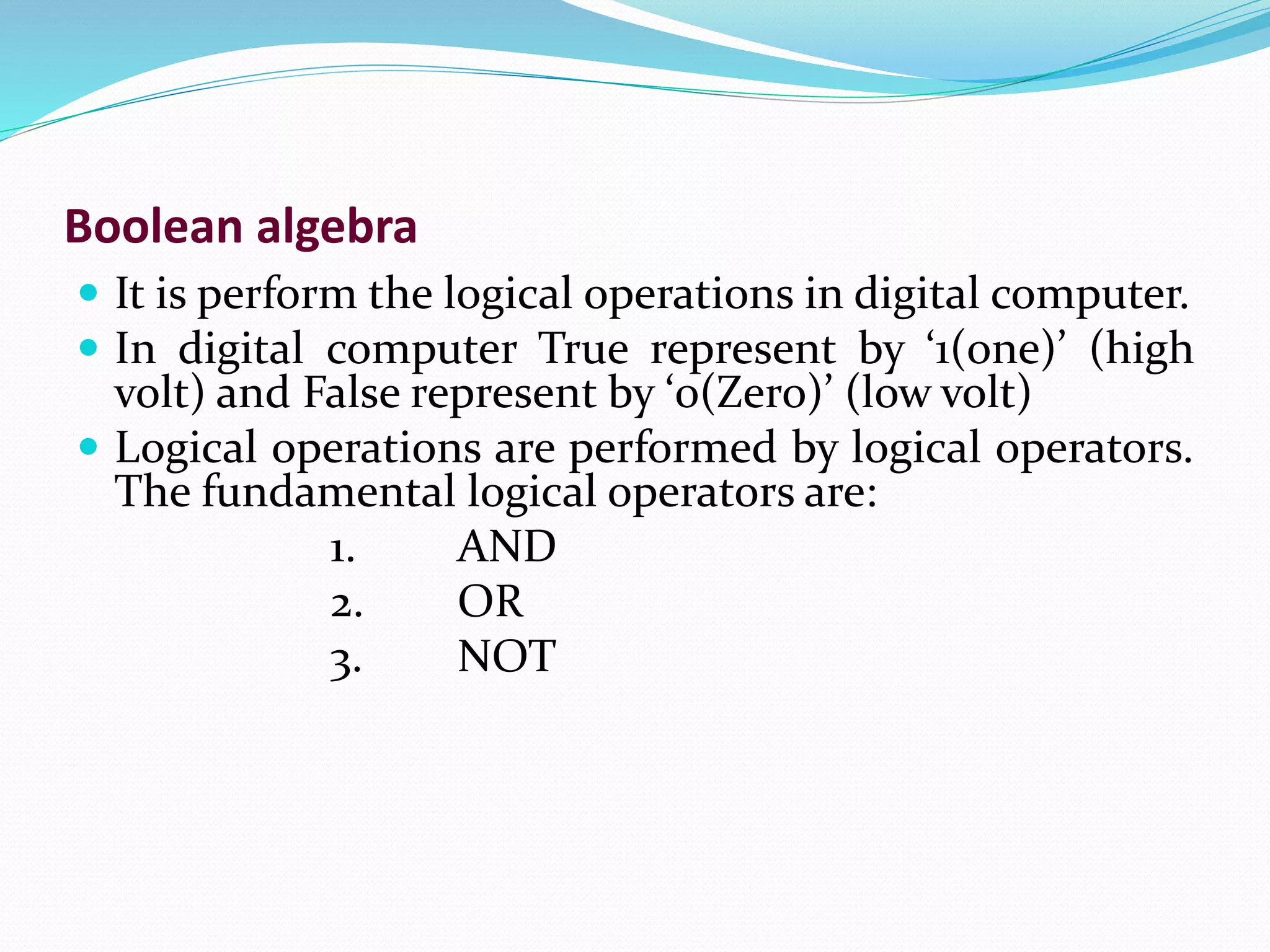
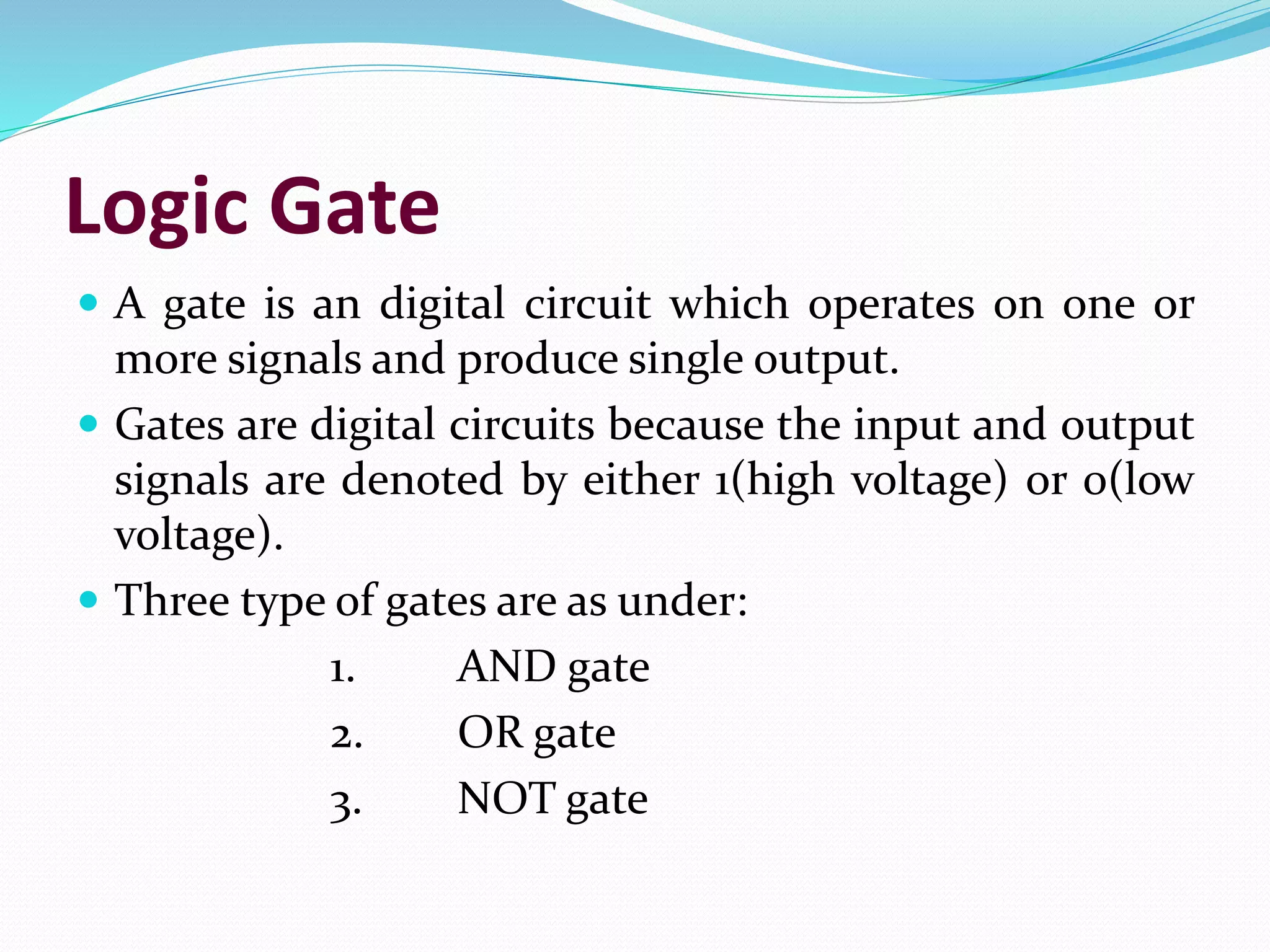
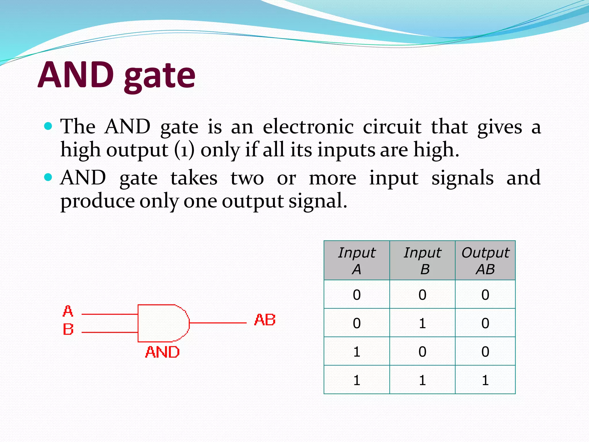
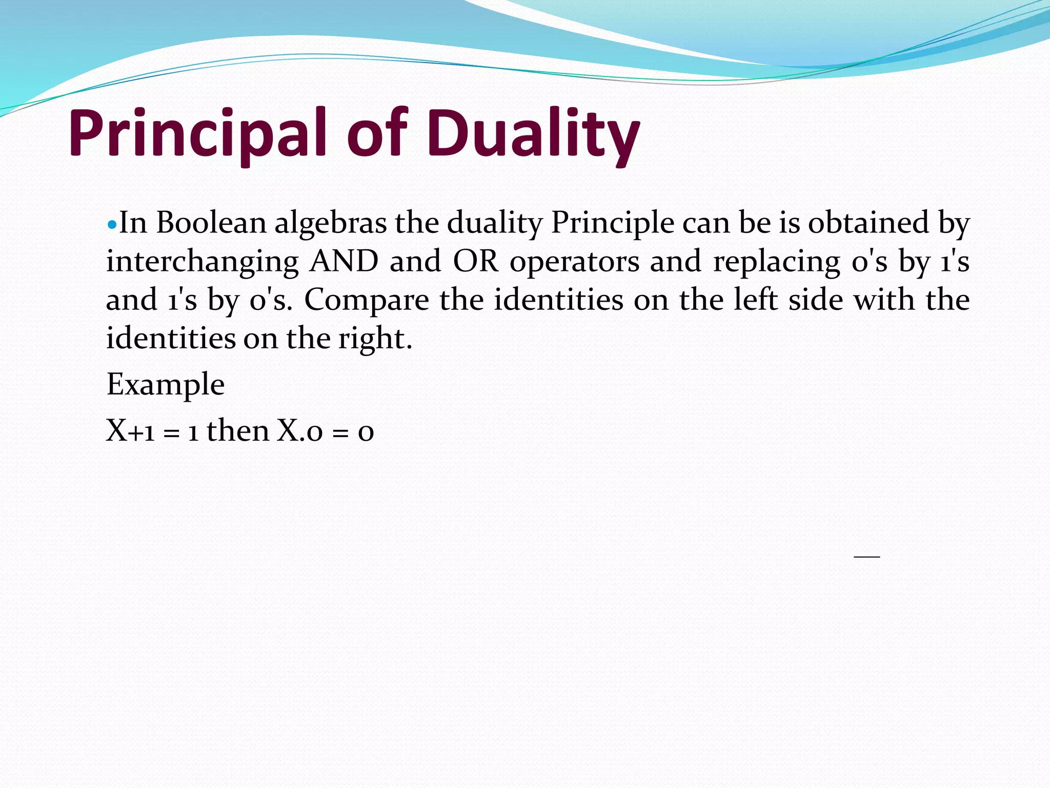
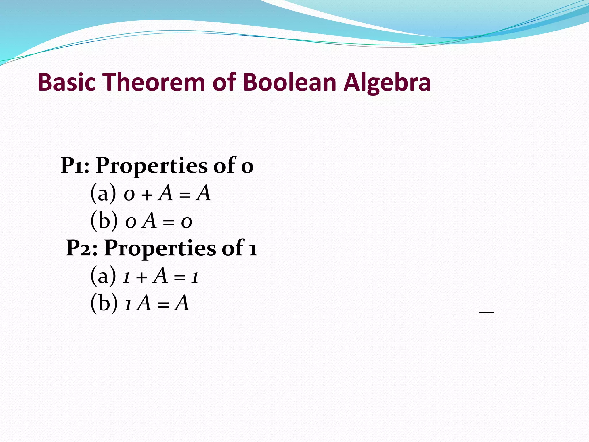
Boolean Algebra
Prof. Neeraj Bhargava
Kapil Chauhan
Department of Computer Science
School of Engineering & Systems Sciences
MDS University, Ajmer
Boolean algebra
 It is perform the logical operations in digital computer.
 In digital computer True represent by ‘1(one)’ (high
volt) and False represent by ‘0(Zero)’ (low volt)
 Logical operations are performed by logical operators.
The fundamental logical operators are:
1. AND
2. OR
3. NOT
Implementation
 Boolean Algebra applied in computers electronic
circuits.
 These circuits perform Boolean operations and these
are called logic circuits or logic gates.
Logic Gate
 A gate is an digital circuit which operates on one or
more signals and produce single output.
 Gates are digital circuits because the input and output
signals are denoted by either 1(high voltage) or 0(low
voltage).
 Three type of gates are as under:
1. AND gate
2. OR gate
3. NOT gate
AND gate
 The AND gate is an electronic circuit that gives a
high output (1) only if all its inputs are high.
 AND gate takes two or more input signals and
produce only one output signal.
Input
A
Input
B
Output
AB
0 0 0
0 1 0
1 0 0
1 1 1
OR gate
 The OR gate is an electronic circuit that gives a high
output (1) if one or more of its inputs are high.
 OR gate also takes two or more input signals and
produce only one output signal.
Input
A
Input
B
Output
A+B
0 0 0
0 1 1
1 0 1
1 1 1
NOT gate
 The NOT gate is an electronic circuit that gives a high output
(1) if its input is low .
 NOT gate takes only one input signal and produce only one
output signal.
 The output of NOT gate is complement of its input.
 It is also called inverter.
Input A Output A
0 1
1 0
Principal of Duality
In Boolean algebras the duality Principle can be is obtained by
interchanging AND and OR operators and replacing 0's by 1's
and 1's by 0's. Compare the identities on the left side with the
identities on the right.
Example
X+1 = 1 then X.0 = 0
Basic Theorem of Boolean Algebra
P1: Properties of 0
(a) 0 + A = A
(b) 0 A = 0
P2: Properties of 1
(a) 1 + A = 1
(b) 1 A = A
Basic Theorem of Boolean Algebra
P3 : Commutative Law
(a) A + B = B + A
(b) A B = B A
P4 : Associate Law
(a) (A + B) + C = A + (B + C)
(b) (A B) C = A (B C)
P5 : Distributive Law
(a) A (B + C) = A B + A C
(b) A + (B C) = (A + B) (A + C)
(c) A+A’B = A+B
Basic Theorem of Boolean Algebra
P6 : Complementary Law
(a) X+X’=1
(b) X.X’=0
P7 : Involution
(a) x’’ = x
P8 : De Morgan's Theorem
(a) (X+Y)’=X’.Y’
(b) (X.Y)’=X’+Y’
Exercise
Q 1. State & Verify De Morgan's Law by using
truth table and algebraically.
Q 2. State and verify distributive law.
Q 3. Draw a logic diagram for the following
expression:
(a) ab+b’c+c’a’
(b) (a+b).(a+b’).c

Boolean algebra

  • 1.
    Boolean Algebra Prof. NeerajBhargava Kapil Chauhan Department of Computer Science School of Engineering & Systems Sciences MDS University, Ajmer
  • 2.
    Boolean algebra  Itis perform the logical operations in digital computer.  In digital computer True represent by ‘1(one)’ (high volt) and False represent by ‘0(Zero)’ (low volt)  Logical operations are performed by logical operators. The fundamental logical operators are: 1. AND 2. OR 3. NOT
  • 3.
    Implementation  Boolean Algebraapplied in computers electronic circuits.  These circuits perform Boolean operations and these are called logic circuits or logic gates.
  • 4.
    Logic Gate  Agate is an digital circuit which operates on one or more signals and produce single output.  Gates are digital circuits because the input and output signals are denoted by either 1(high voltage) or 0(low voltage).  Three type of gates are as under: 1. AND gate 2. OR gate 3. NOT gate
  • 5.
    AND gate  TheAND gate is an electronic circuit that gives a high output (1) only if all its inputs are high.  AND gate takes two or more input signals and produce only one output signal. Input A Input B Output AB 0 0 0 0 1 0 1 0 0 1 1 1
  • 6.
    OR gate  TheOR gate is an electronic circuit that gives a high output (1) if one or more of its inputs are high.  OR gate also takes two or more input signals and produce only one output signal. Input A Input B Output A+B 0 0 0 0 1 1 1 0 1 1 1 1
  • 7.
    NOT gate  TheNOT gate is an electronic circuit that gives a high output (1) if its input is low .  NOT gate takes only one input signal and produce only one output signal.  The output of NOT gate is complement of its input.  It is also called inverter. Input A Output A 0 1 1 0
  • 8.
    Principal of Duality InBoolean algebras the duality Principle can be is obtained by interchanging AND and OR operators and replacing 0's by 1's and 1's by 0's. Compare the identities on the left side with the identities on the right. Example X+1 = 1 then X.0 = 0
  • 9.
    Basic Theorem ofBoolean Algebra P1: Properties of 0 (a) 0 + A = A (b) 0 A = 0 P2: Properties of 1 (a) 1 + A = 1 (b) 1 A = A
  • 10.
    Basic Theorem ofBoolean Algebra P3 : Commutative Law (a) A + B = B + A (b) A B = B A P4 : Associate Law (a) (A + B) + C = A + (B + C) (b) (A B) C = A (B C) P5 : Distributive Law (a) A (B + C) = A B + A C (b) A + (B C) = (A + B) (A + C) (c) A+A’B = A+B
  • 11.
    Basic Theorem ofBoolean Algebra P6 : Complementary Law (a) X+X’=1 (b) X.X’=0 P7 : Involution (a) x’’ = x P8 : De Morgan's Theorem (a) (X+Y)’=X’.Y’ (b) (X.Y)’=X’+Y’
  • 12.
    Exercise Q 1. State& Verify De Morgan's Law by using truth table and algebraically. Q 2. State and verify distributive law. Q 3. Draw a logic diagram for the following expression: (a) ab+b’c+c’a’ (b) (a+b).(a+b’).c