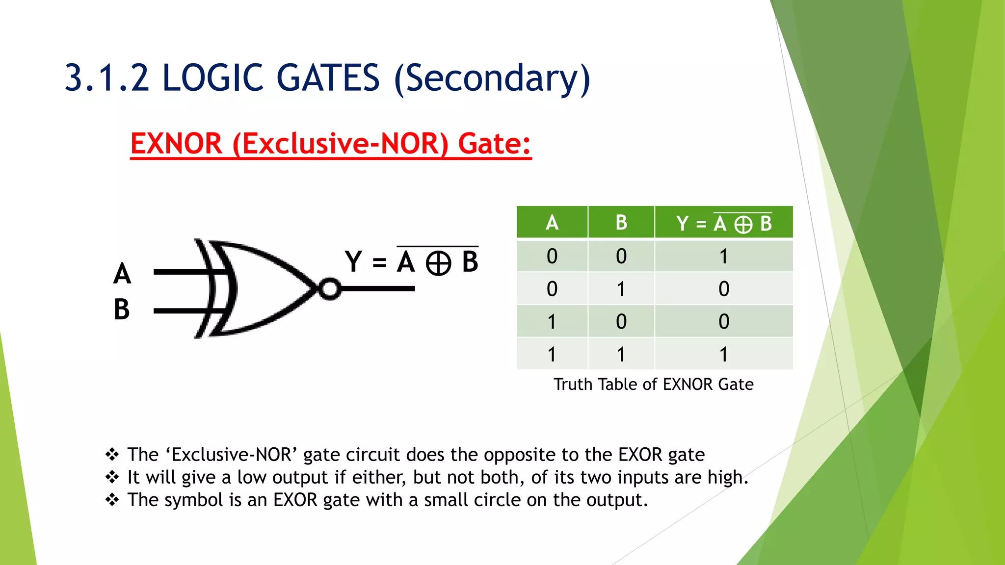
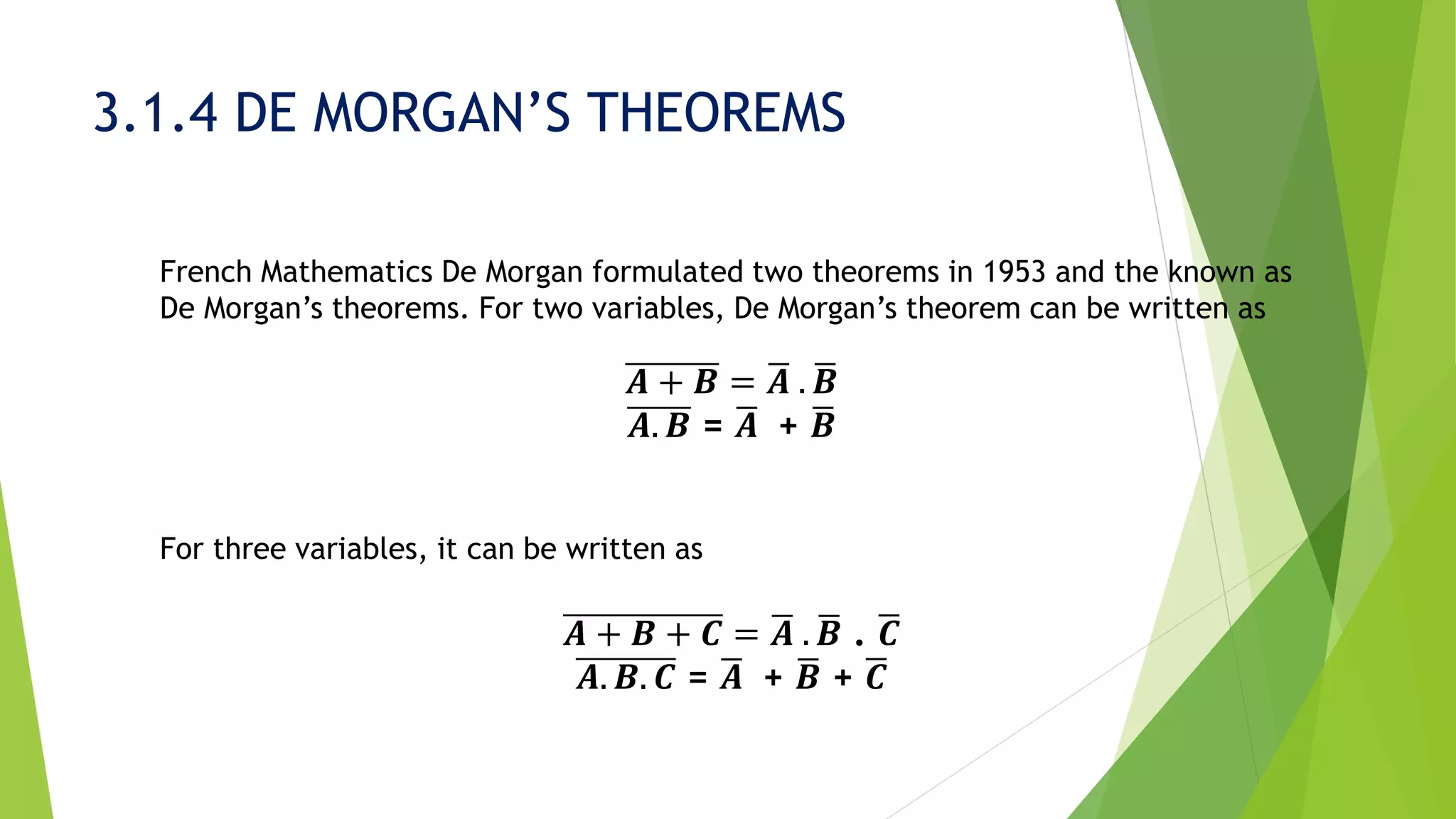
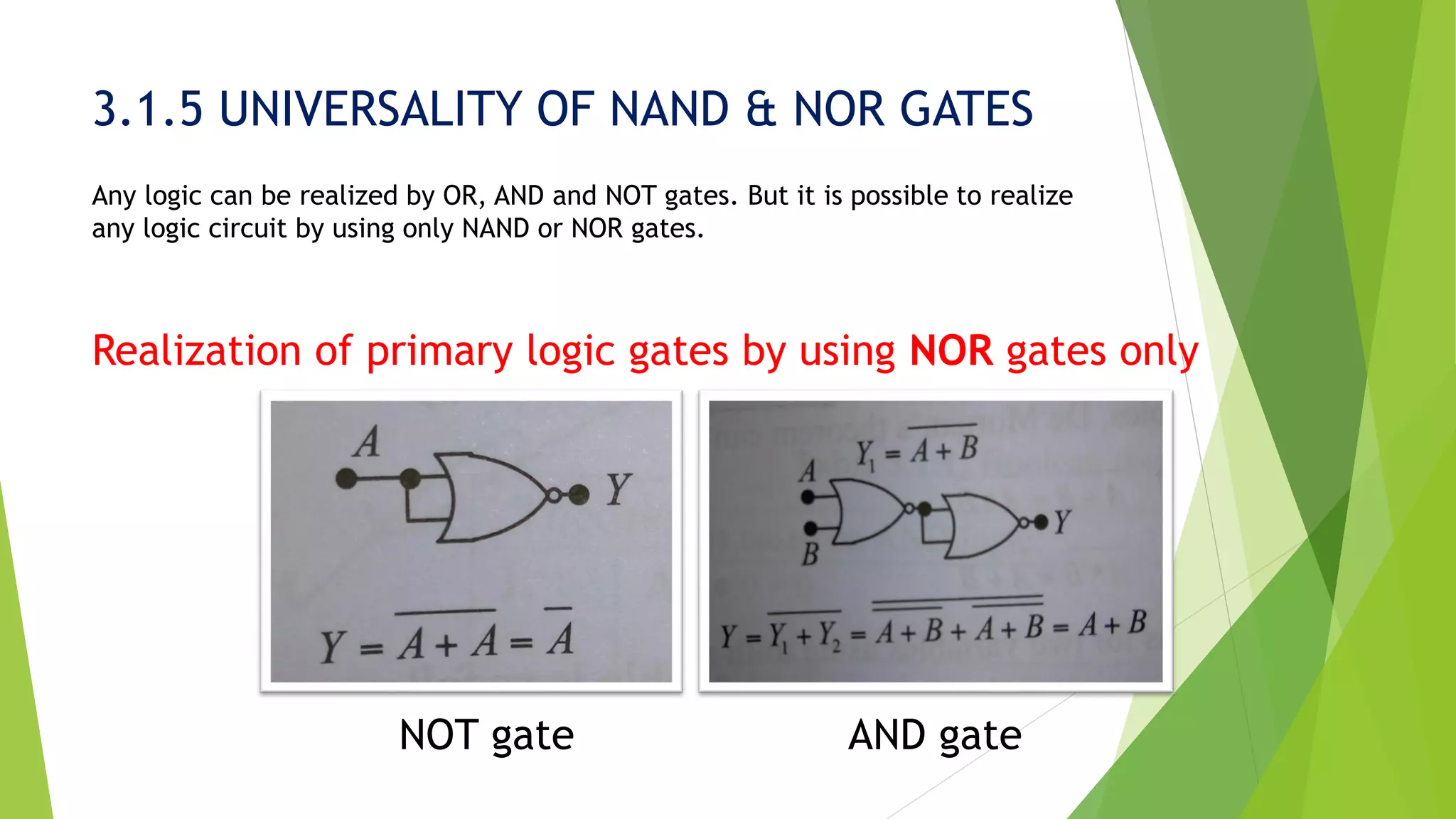
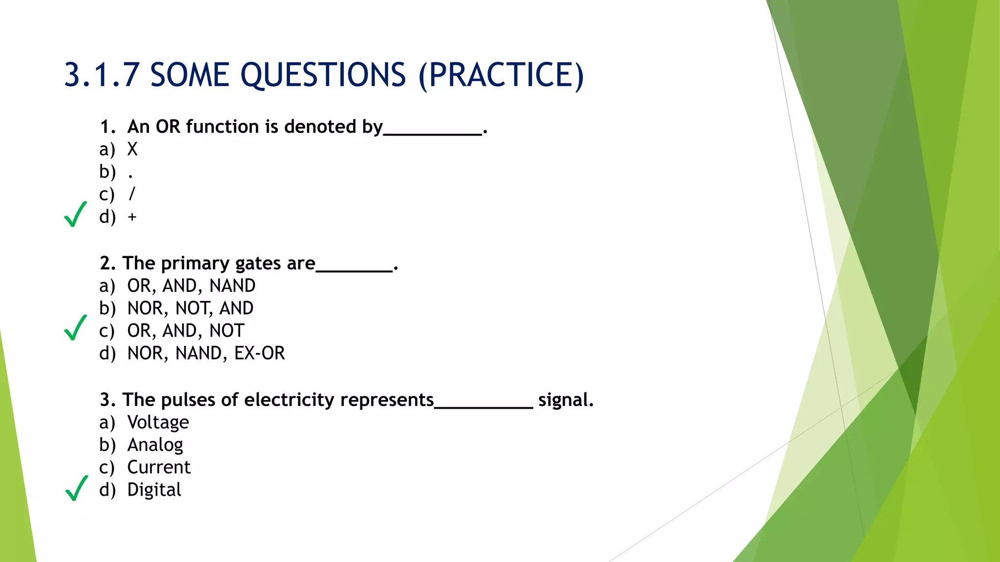
The document covers the fundamentals of logic gates, including primary gates like AND, OR, and NOT, as well as secondary gates such as NAND, NOR, XOR, and XNOR. It explains Boolean theorems, De Morgan's theorems, and the universality of NAND and NOR gates in constructing logic circuits. Additionally, practice questions are included to test understanding of the concepts presented.

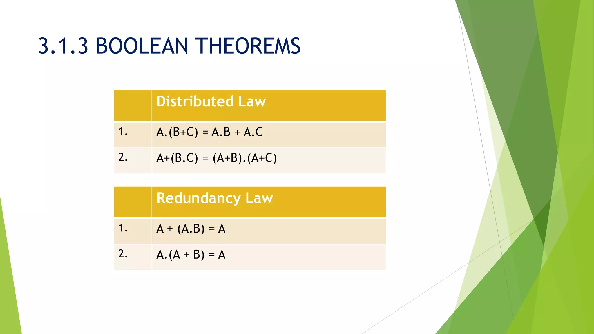
![3.1.3 BOOLEAN THEOREMS
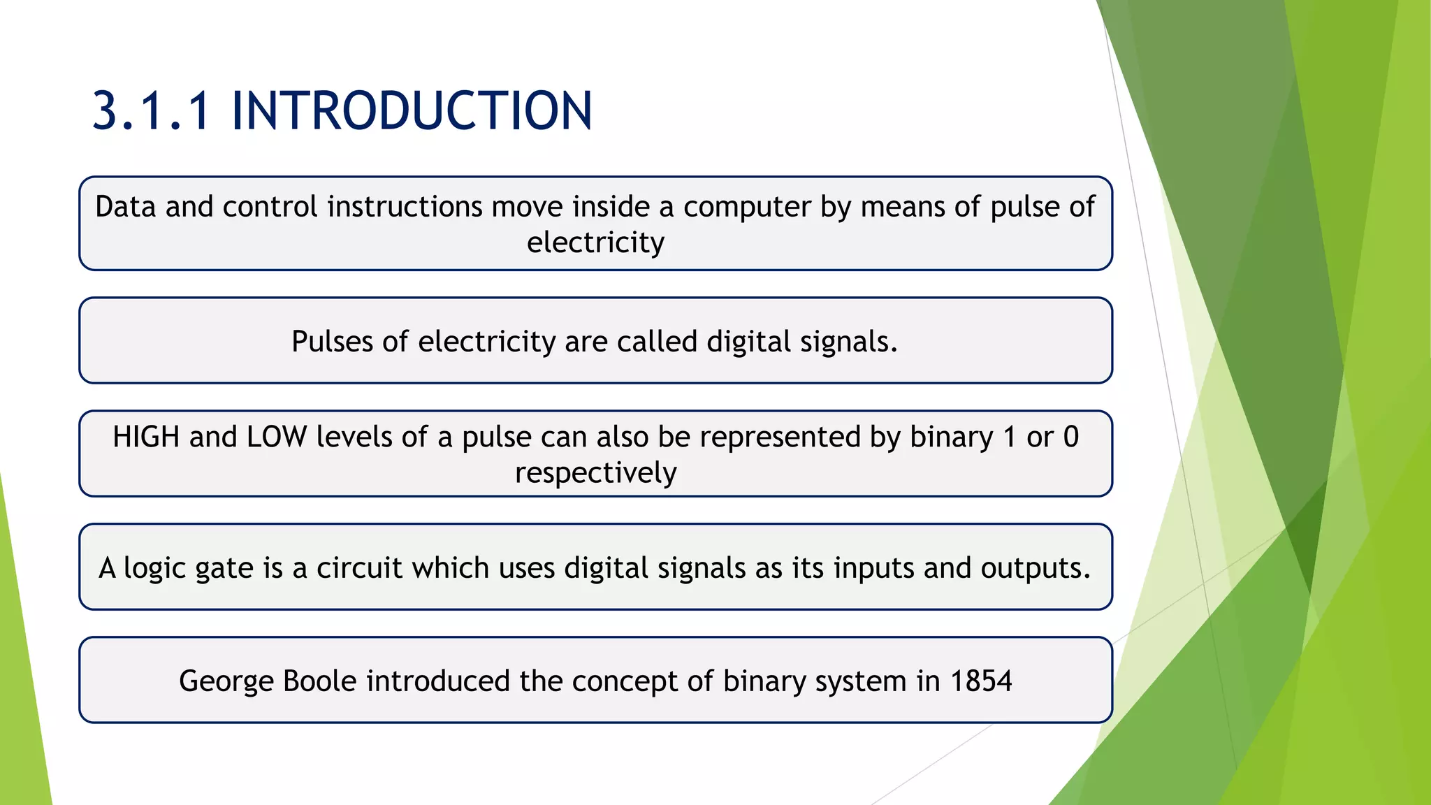
Logic circuits can be simplified by Boolean algebra and simplification of logic functions
and logic circuits is an important application of Boolean algebra. Important Boolean
Theorems are given in the table.
Theorems based on AND logic Example
1. A.0 = 0 1.0 = 0
0.0 = 0
2. A.1 = A 1.1 = 1
0.1 = 0
3. A.A = A 1.1 = 1
0.0 = 0
4. A. ഥ𝑨 = 0 1.0 = 0
0.1 = 0
5. A.B = B.A [Commutative Law]
6. A.B.C = (A.B).C = A.(B.C) [Associative Law]](https://image.slidesharecdn.com/presentationonlogicgatesanupam-190301143720/75/Presentation-on-Logic-Fundamental-by-Anupam-14-2048.jpg)
![3.1.3 BOOLEAN THEOREMS
Theorems based on OR logic Example
1. A + 0 = A 1 + 0 = 1
0 + 0 = 0
2. A + 1 = 1 1 + 1 = 1
0 + 1 = 1
3. AA = A 1 + 1 = 1
0 + 0 = 0
4. A + ഥ𝑨 = 1 1 + 0 = 1
0 + 1 = 1
5. A+B = B+A [Commutative Law]
6. A+B+C = (A+B)+C = A+(B+C) [Associative Law]](https://image.slidesharecdn.com/presentationonlogicgatesanupam-190301143720/75/Presentation-on-Logic-Fundamental-by-Anupam-15-2048.jpg)
![3.1.3 BOOLEAN THEOREMS
Example: Simplify Y = A . (B + C) . ഥ𝑨 . B . D
Given,
Y = A . (B + C) . ഥ𝑨 . B . D
= A . ഥ𝑨 . (B + C) . B . D
= 0 [As A . ഥ𝑨 = 0] (answer)
Your Work:
Simplify it, Y = (A + B) . (A + B) + C](https://image.slidesharecdn.com/presentationonlogicgatesanupam-190301143720/75/Presentation-on-Logic-Fundamental-by-Anupam-17-2048.jpg)


![Chapter 3 computer Boolean Algebra 2[1].pptx](https://cdn.slidesharecdn.com/ss_thumbnails/chapter3booleanalgebra21-240928031107-5861eb7e-thumbnail.jpg?width=640&height=640&fit=bounds)