Downloaded 556 times


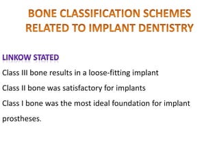
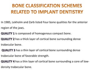
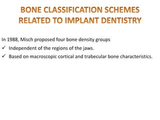
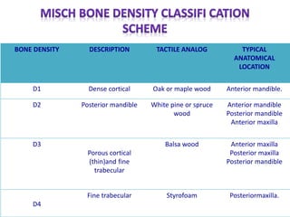
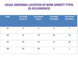

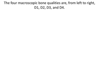
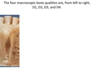
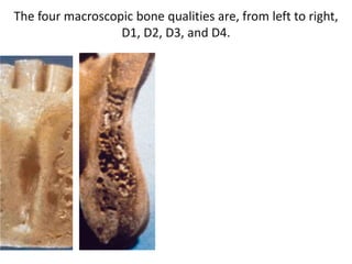
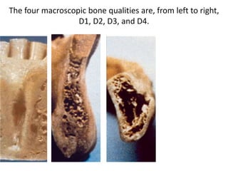
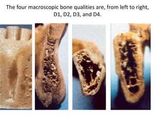
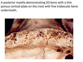
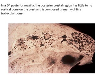
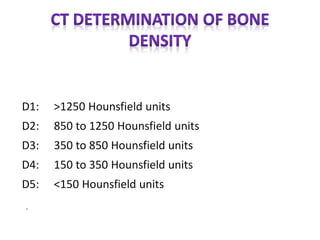


The document discusses bone density and its importance in implant dentistry. It describes four classifications of bone density (D1-D4) based on macroscopic characteristics, with D1 being the densest. The anterior mandible typically has the densest D1/D2 bone, while the posterior maxilla has the least dense D4 bone. Determining bone density accurately using CT scans is important for developing an appropriate treatment plan and ensuring implant success long-term by avoiding pathological overload conditions.


![Bone Density.pptxdfrftu890-/897\]lpjkgfds](https://cdn.slidesharecdn.com/ss_thumbnails/bonedensity-251027073618-7a77a65b-thumbnail.jpg?width=640&height=640&fit=bounds)


