OCCLUSAL
CONSIDERATIONS FOR
IMPLANT- SUPPORTED
PROSTHESIS
PRESENTED BY
DR. RAJ SALVI
GUIDED BY
DR. JYOTI TEMBHURNE
DR. MANISH CHAUHAN
CONTENTS
 INTRODUCTION
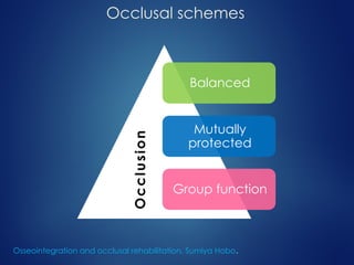
 OCCLUSAL SCHEMES
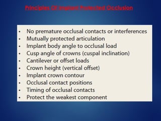
 IMPLANT PROTECTIVE OCCLUSION(IPO)
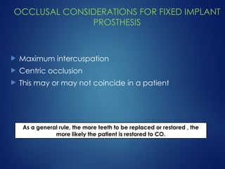
 OCCLUSAL CONSIDERATIONS FOR FIXED IMPLANT PROSTHESIS
Premature occlusal contacts
Implant body orientation
Force direction and bone mechanics
Prosthetic angled loads
Posterior crown cusp angle
Mutually protected articulation
Cantilevers and IPO
Crown height and IPO
Posterior implant crown contour
Posterior occlusal contact positions
Timing of occlusal contacts
Design to the weakest arch
 CONCLUSION
INTRODUCTION
 Rehabilitation using implant supported prosthesis
involves multiple steps and meticulous planning.
 Once surgical placement is done, the long term
success of implant has been associated to
restorative dentist’s knowledge of prosthetic
dentistry.
 The mechanical setting in which implant function,
mechanical stress/ strain > bone loss.
1) Misch CE: Early crestal bone loss etiology and its effect on treatment planning for implants, Postgrad Dent 3:3–17, 1995.
2) Isidor F: Loss of osteointegration caused by occlusal load of oral implants, Clin Oral Implants Res 7:143–152, 1996.
 Occlusal setting determines the mechanical stress.
 The treatment plan > design, number and position
> occlusal load on implant.
 Implant rehabilitation is occlusal scheme that
minimizes risk factors and allows the restoration to
function in harmony with the rest of the
stomatognathic system.
1) Isidor R: Histological evaluation of peri-implant bone at implants subjected to occlusal overload or plaque accumulation, Clin Oral Implants Res 8:1–9, 1997.
2) Rangert B, Krogh PH, Langer B, et al: Bending overload and implant fracture: a retrospective clinical analysis, Int J Oral Maxillofac Implants 7:40–44, 1995.
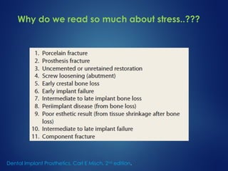
Why do we read so much about stress..???
Dental Implant Prosthetics, Carl E Misch, 2nd
edition.
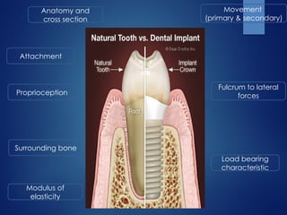
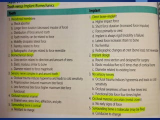
Attachment
Proprioception
Load bearing
characteristic
Fulcrum to lateral
forces
Modulus of
elasticity
Movement
(primary & secondary)
Anatomy and
cross section
Surrounding bone
Occlusal schemes
Balanced
Mutually
protected
Group function
O
c
c
l
u
s
i
o
n
Osseointegration and occlusal rehabilitation, Sumiya Hobo.
Balanced occlusion
The bilateral simultaneous anterior
and posterior occlusal contact of
teeth in centric and eccentric
positions.
The glossary of prosthodontic terms. J Prosthet Dent 2005; 94:10–92.
Mutually protected occlusion
An occlusal scheme in which the posterior teeth prevent excessive
contact of the anterior teeth in maximum intercuspation and the
anterior teeth disengage the posterior teeth in all mandibular
excursive movements.
 Posterior teeth protect the anterior teeth in centric
position
 Incisors protect the canine and posterior teeth during
protrusive movement
 canines protect the incisors and posterior teeth during
lateral movements
Osseointegration and occlusal rehabilitation, Sumiya Hobo.
Group functional occlusion
Multiple contact relationship between maxillary and mandibular in lateral
movements on working side, where by simultaneous contact of several teeth
acts as a group to distribute occlusal forces.
 Often encountered in elderly
patients.
 Provides a harmonious
balance to structures of
stomatognathic system.
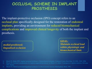
OCCLUSAL SCHEME IN IMPLANT
PROSTHESIS
The implant-protective occlusion (IPO) concept refers to an
occlusal plan specifically designed for the restoration of endosteal
implants, providing an environment for reduced biomechanical
complications and improved clinical longevity of both the implant and
prosthesis.
medial-positioned;
lingualized occlusion
1) Misch CE, Bidez MW: Implant protected occlusion: a biomechanical rationale, Compend Contin Dent Educ 15:1330– 1343, 1994.
2) Misch CE: Occlusal considerations for implant-supported prostheses. In Misch CE, editor: Contemporary implant dentistry, St Louis,
1993, Mosby.
3) Misch CE: Medial positioned lingualized occlusion. In Misch Institute manual, Birmingham, Mich, 1991.
GOAL:
Maintain occlusal load
within physiologic and
biomechanical limit.
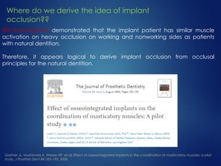
Electromyograms demonstrated that the implant patient has similar muscle
activation on heavy occlusion on working and nonworking sides as patients
with natural dentition.
Therefore, it appears logical to derive implant occlusion from occlusal
principles for the natural dentition.
Gartner JL, Mushimoto K, Weber HP, et al: Effect of osseointegrated implants in the coordination of masticatory muscles: a pilot
study, J Prosthet Dent 84:185–193, 2000
Where do we derive the idea of implant
occlusion??
Principles Of Implant Protected Occlusion
OCCLUSAL CONSIDERATIONS FOR FIXED IMPLANT
PROSTHESIS
 Maximum intercuspation
 Centric occlusion
 This may or may not coincide in a patient
As a general rule, the more teeth to be replaced or restored , the
more likely the patient is restored to CO.
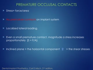
PREMATURE OCCLUSAL CONTACTS
 Stress= force/area
 No premature contacts on implant system
 Localized lateral loading.
 Even a small premature contact, magnitude a stress increases
proportionately {S = F/A}
 Inclined plane > the horizontal component > the shear stresses
Dental Implant Prosthetics, Carl E Misch, 2nd
edition.
 In parafunction > duration and magnitude of occlusal forces
 The elimination of premature contact is more critical than in
natural teeth because of lack of proprioception and the implant
inability to move and dissipiate forces.
Dental Implant Prosthetics, Carl E Misch, 2nd
edition.
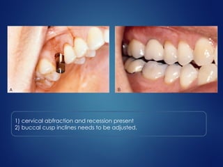
1) cervical abfraction and recession present
2) buccal cusp inclines needs to be adjusted.
IMPLANT BODY ORIENTATION
 Forces (vectors) defined, based on magnitude and
direction.
 Occlusal forces are 3 dimensional with components
directed along one or more clinical coordinate axes
 Same magnitude of force can have dramatical effects
based on the direction of load.
Dental Implant Prosthetics, Carl E Misch, 2nd
edition.
PERPENDICULAR TO CURVE OF SPEE AND WILSON IN
NATURAL DENTITION
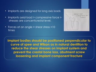
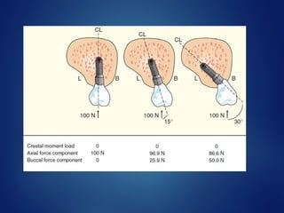
• Implants are designed for long axis loads
• Implants axial load > compressive force >
stresses are concentcrestal level.
• Forces at an angle > shear stress >10
times
Implant bodies should be positioned perpendicular to
curve of spee and Wilson as in natural dentition to
reduce the shear stresses on implant system and
prevent the crestal bone loss, abutment screw
loosening and implant component fracture
FORCE DIRECTION AND BONE MECHANICS
Anisotrophy of bone- it refers to the character of bone whereby
its meachanical properties depend on the direction in which
bone is loaded and the type of force applied.
BONE IS STRONGER IN COMPRESSION, 30%
WEAKER IN TENSION, 65% WEAKER IN SHEAR
Porcelain and titanium are also weaker in shear component of
load
IPO attemps to eliminate all shear loads to
implant system
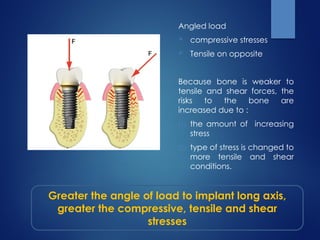
Angled load
 compressive stresses
 Tensile on opposite
Because bone is weaker to
tensile and shear forces, the
risks to the bone are
increased due to :
(1) the amount of increasing
stress
(2) type of stress is changed to
more tensile and shear
conditions.
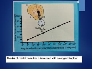
Greater the angle of load to implant long axis,
greater the compressive, tensile and shear
stresses
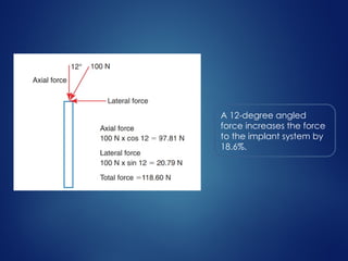
A 12-degree angled
force increases the force
to the implant system by
18.6%.
• Force (shear, tensile) is detrimental;
• Not only is the bone weakest to shear loads, but forces
physiologic limit of compressive and tensile strengths of
bone.
IPO attempts to eliminate lateral or angled loads to an
implant-supported prosthesis because the magnitude of
the force increases and the strength of the bone
decreases.
Reilly DT, Burstein AH: The elastic and ultimate properties of compact bone tissue, J Biomech 80:393–405, 1975.
The risk of crestal bone loss is increased with an angled implant
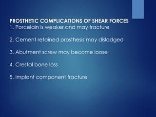
PROSTHETIC COMPLICATIONS OF SHEAR FORCES
1. Porcelain is weaker and may fracture
2. Cement retained prosthesis may dislodged
3. Abutment screw may become loose
4. Crestal bone loss
5. Implant component fracture
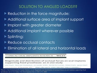
SOLUTION TO ANGLED LOADS??
 Reduction in the force magnitude;
 Additional surface area of implant support
 Implant with greater diameter
 Additional implant wherever possible
 Splinting;
 Reduce occlusal contacts
 Elimination of all lateral and horizontal loads
Duyck J, Van Oosterwyck H, Vander Sloten J, et al: Magnitude and distribution of occlusal forces on oral implants supporting fixed
prostheses: an in vivo study, Clin Oral Implants Res 11:465–475, 2000
POSTERIOR CROWN CUSP ANGLE
• Greater cusp angle > more esthetics
and increased food chewing efficiency
• Occlusal contact on angled cusp >
increased angle load and makes it
premature contact even if it is not
• Solution
1. Occlusal contact on flat surface
2. Increased fossa by 2-3 mm
3. Recounturing of opposing cusp
Miyata T, Kobayashi Y, Araki H, et al: The influence of controlled occlusal overload on peri-implant time. 4. A histologic study , Int J Oral Maxillofac
Implants 17:384–390, 2002.
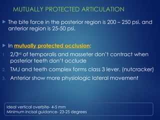
MUTUALLY PROTECTED ARTICULATION
 The bite force in the posterior region is 200 – 250 psi. and
anterior region is 25-50 psi.
 In mutually protected occlusion:
1. 2/3rd
of temporalis and masseter don’t contract when
posterior teeth don’t occlude
2. TMJ and teeth complex forms class 3 lever. (nutcracker)
3. Anterior show more physiologic lateral movement
Ideal vertical overbite- 4-5 mm
Minimum incisal guidance- 23-25 degrees
MUTUALLY PROTECTED ARTICULATION
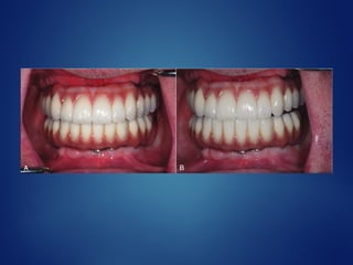
 Protrusive mandibular movement - central and lateral
incisors disocclude the posteriors
 Lateral excursions- canine (central and lateral when
possible) disocclude the posteriors
 CO- posterior and canine occlude, when central and
lateral are natural they may also occlude, (when central
and lateral are implants they should not occlude if
opposing dentition is also implant supported)
When single missing canine
 No protrusive contact , if at all necessary give light contact
 Lateral excursion > give slight contact on lateral incisor
 Under heavy bite it might contact as same intensity as lateral
inciosor
CANTILEVERS AND IPO
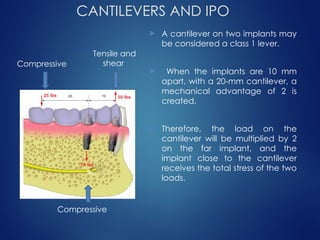
 A cantilever on two implants may
be considered a class 1 lever.
 When the implants are 10 mm
apart, with a 20-mm cantilever, a
mechanical advantage of 2 is
created.
 Therefore, the load on the
cantilever will be multiplied by 2
on the far implant, and the
implant close to the cantilever
receives the total stress of the two
loads.
Compressive
Tensile and
shear
Compressive
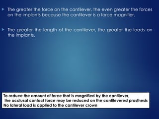
 The greater the force on the cantilever, the even greater the forces
on the implants because the cantilever is a force magnifier.
 The greater the length of the cantilever, the greater the loads on
the implants.
To reduce the amount of force that is magnified by the cantilever,
the occlusal contact force may be reduced on the cantilevered prosthesis
No lateral load is applied to the cantilever crown
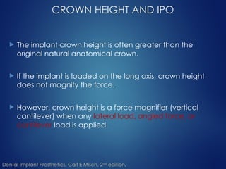
CROWN HEIGHT AND IPO
 The implant crown height is often greater than the
original natural anatomical crown.
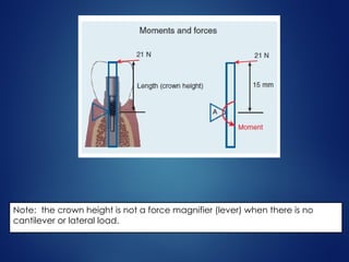
 If the implant is loaded on the long axis, crown height
does not magnify the force.
 However, crown height is a force magnifier (vertical
cantilever) when any lateral load, angled force, or
cantilever load is applied.
Dental Implant Prosthetics, Carl E Misch, 2nd
edition.
Note: the crown height is not a force magnifier (lever) when there is no
cantilever or lateral load.
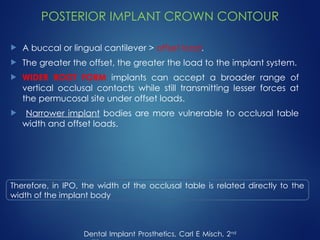
POSTERIOR IMPLANT CROWN CONTOUR
 A buccal or lingual cantilever > offset load.
 The greater the offset, the greater the load to the implant system.
 WIDER ROOT FORM implants can accept a broader range of
vertical occlusal contacts while still transmitting lesser forces at
the permucosal site under offset loads.
 Narrower implant bodies are more vulnerable to occlusal table
width and offset loads.
Dental Implant Prosthetics, Carl E Misch, 2nd
Therefore, in IPO, the width of the occlusal table is related directly to the
width of the implant body
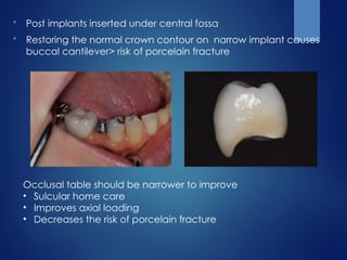
 Post implants inserted under central fossa
 Restoring the normal crown contour on narrow implant causes
buccal cantilever> risk of porcelain fracture
Occlusal table should be narrower to improve
• Sulcular home care
• Improves axial loading
• Decreases the risk of porcelain fracture
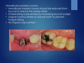
Mandibular posterior crowns
• Mandibular implant crowns should be reduced from
buccal to reduce the stamp offset
• Cheek biting is prevented by increasing buccal overjet
• Lingual contour similar to natural tooth to prevent
tongue biting
• No lingual cusp contact
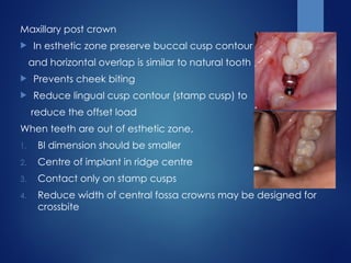
Maxillary post crown
 In esthetic zone preserve buccal cusp contour
and horizontal overlap is similar to natural tooth
 Prevents cheek biting
 Reduce lingual cusp contour (stamp cusp) to
reduce the offset load
When teeth are out of esthetic zone,
1. Bl dimension should be smaller
2. Centre of implant in ridge centre
3. Contact only on stamp cusps
4. Reduce width of central fossa crowns may be designed for
crossbite
POSTERIOR OCCLUSAL CONTACT
POSITIONS
 Ideal contact points
 The ideal occlusal contacts per tooth should have
minimum offset loads to the implant body, the
central fossa is the logical primary occlusal contact
position.
Dental Implant Prosthetics, Carl E Misch, 2nd
edition.
 The ideal primary occlusal contacts therefore will
reside within the diameter of the implant within the
central fossa.
 Secondary occlusal contacts should remain within 1
mm of the periphery of the implant to decrease
moment loads.
 Occlusal contact on mesial or distal is a cantilever
load While occlusal contact on buccal or lingual is
an offset load
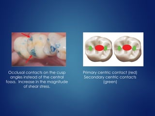
Primary centric contact (red)
Secondary centric contacts
(green)
Occlusal contacts on the cusp
angles instead of the central
fossa. Increase in the magnitude
of shear stress.
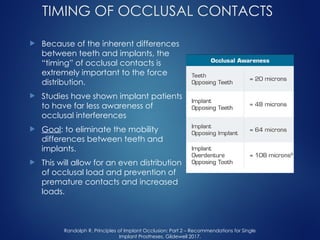
TIMING OF OCCLUSAL CONTACTS
 Because of the inherent differences
between teeth and implants, the
“timing” of occlusal contacts is
extremely important to the force
distribution.
 Studies have shown implant patients
to have far less awareness of
occlusal interferences
 Goal: to eliminate the mobility
differences between teeth and
implants.
 This will allow for an even distribution
of occlusal load and prevention of
premature contacts and increased
loads.
Randolph R. Principles of Implant Occlusion: Part 2 – Recommendations for Single
Implant Prostheses, Glidewell 2017.
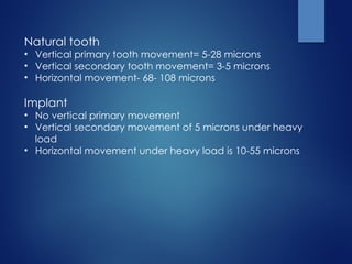
Natural tooth
• Vertical primary tooth movement= 5-28 microns
• Vertical secondary tooth movement= 3-5 microns
• Horizontal movement- 68- 108 microns
Implant
• No vertical primary movement
• Vertical secondary movement of 5 microns under heavy
load
• Horizontal movement under heavy load is 10-55 microns
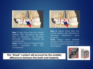
Step 2: Heavy force bite into
centric relation with shimstock in
between. Resistance upon
removal.
Goal: Heavy force exerted
equals to PDL compression. Thus
an even contact between tooth
and implant.
Step 1: Light force bite into centric
relation with Shimstock less than
25u) in between. All contacts
removed. Shimstock retrieval be
unobstructed.
Goal: Great force on natural teeth
which coincides with PDL
compression.
This “timed” contact will account for the mobility
differences between the teeth and implants.
DESIGN TO THE WEAKEST ARCH
 The weakest component philosophy is used when one
opposing segment is at more risk of complications than an
opposing area.
 Goal of ipo
1. Identify the weakest link
2. Design prosthesis and occlusal scheme to protect it
 The amount of force distributed to a system can be
reduced by stress relieving components that may
dramatically reduce impact loads to the implant support.
 The soft tissue of a conventional complete removable
prosthesis opposing implant prosthesis is displaced more
than 2 mm and is an efficient stress reducer.
 Lateral loads do not causes great crestal load to the
implants because the opposing prosthesis is not rigid.
Dental Implant Prosthetics, Carl E Misch, 2nd
 The weakest component philosophy also applies to axial
occlusal contacts in implant body in the presence of
cantilevers and offset loaded areas.
 During excursion, Absence of contacts on posterior
cantilevers and anterior offset pontics is recommended
which minimizes the loads on the terminal implant
abutments.
 When cantilever pontics are in both arches, they should
oppose each other.
 If cantilever pontic is present only in one arch it is better
for mandibular cantilever pontics to oppose maxillary
implants than the reverse situation.
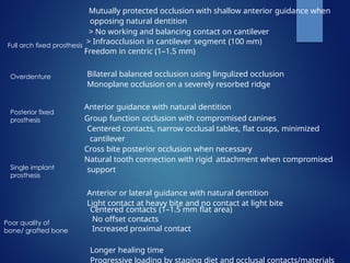
Mutually protected occlusion with shallow anterior guidance when
opposing natural dentition
> No working and balancing contact on cantilever
> Infraocclusion in cantilever segment (100 mm)
Freedom in centric (1–1.5 mm)
Bilateral balanced occlusion using lingulized occlusion
Monoplane occlusion on a severely resorbed ridge
Anterior guidance with natural dentition
Group function occlusion with compromised canines
Centered contacts, narrow occlusal tables, flat cusps, minimized
cantilever
Cross bite posterior occlusion when necessary
Natural tooth connection with rigid attachment when compromised
support
Anterior or lateral guidance with natural dentition
Light contact at heavy bite and no contact at light bite
Centered contacts (1–1.5 mm flat area)
No offset contacts
Increased proximal contact
Longer healing time
Progressive loading by staging diet and occlusal contacts/materials
Full arch fixed prosthesis
Overdenture
Posterior fixed
prosthesis
Single implant
prosthesis
Poor quality of
bone/ grafted bone
CONCLUSION
 Any complex engineering structure typically will fail
at its weakest link, and dental implant structures are
no exception.
 Thus, all treatment planning decisions for IPO should
be based on careful consideration of (1) identifying
the weakest link in the overall restoration and (2)
establishing occlusal and prosthetic schemes to
protect that component of the structure.
The IPO concept addresses several conditions
to decrease stress to the implant system,
including implant body angle to occlusal load,
cusp angle of crowns, mutually protected
articulation, cantilever or offset distance, crown
height, crown contour, the timing of occlusal
contacts, and protection of the weakest
component.
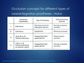
Occlusion concept for different types of
osseointegration prostheses - Hobo
Osseointegration and occlusal rehabilitation, Sumiya Hobo.
References
 Dental Implant Prosthetics, Carl E Misch, 2nd
edition.
 Osseointegration and occlusal rehabilitation, Sumiya Hobo.
 Gartner JL, Mushimoto K, Weber HP, et al: Effect of osseointegrated
implants in the coordination of masticatory muscles: a pilot study, J
Prosthet Dent 84:185–193, 2000.
 Miyata T, Kobayashi Y, Araki H, et al: The influence of controlled
occlusal overload on peri-implant time. 4. A histologic study , Int J
Oral Maxillofac Implants 17:384–390, 2002.
 Duyck J, Van Oosterwyck H, Vander Sloten J, et al: Magnitude and
distribution of occlusal forces on oral implants supporting fixed
prostheses: an in vivo study, Clin Oral Implants Res 11:465–475, 2000.
 Randolph R. Principles of Implant Occlusion: Part 2 –
Recommendations for Single Implant Prostheses, Glidewell 2017.
THANK YOU