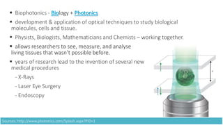
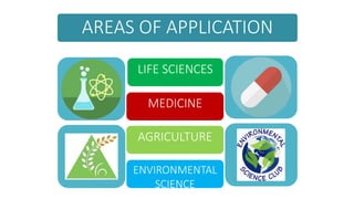
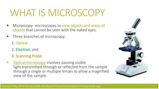
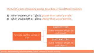
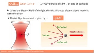
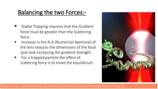
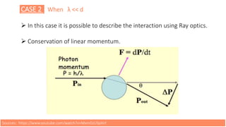
TEAM
 Pranav Negi
 Sarthak Kala
 Tanish Garg
 Tushar Swami
 Vikas Prasad
ACKNOWLEDGEMENT
We would like to express our special thanks of gratitude and respect to our teachers
Dr. Chhavi Bhatnagar and Ms. Sangeeta Yadav who gave us the golden opportunity to
present this wonderful presentation on the topic (Biophotonics), which also helped
us in doing a lot of Research and we came to know about new things. We are really
thankful to them.
WHAT
IS
BIOPHOTONICS ?
 Biophotonics - Biology + Photonics
 development & application of optical techniques to study biological
molecules, cells and tissue.
 Physists, Biologists, Mathematicians and Chemists – working together.
 allows researchers to see, measure, and analyse
living tissues that wasn’t possible before.
 years of research lead to the invention of several new
medical procedures
- X-Rays
- Laser Eye Surgery
- Endoscopy
Sources: http://www.photonics.com/Splash.aspx?PID=1
AREAS OF APPLICATION
LIFE SCIENCES
MEDICINE
AGRICULTURE
ENVIRONMENTAL
SCIENCE
MICROSCOPY
WHAT IS MICROSCOPY
 Microscopy- microscopes to view objects and areas of
objects that cannot be seen with the naked eyes.
 Three branches of microscopy:
1. Optical
2. Electron, and
3. Scanning Probe
 Optical microscopy involves passing visible
light transmitted through or reflected from the sample
through a single or multiple lenses to allow a magnified
view of the sample.
Sources: http://microscopy.duke.edu/learn/introtomicroscopy/confocalpinhole.jpg
CONFOCAL MICROSCOPY
• A laser is used to provide the excitation light
• The laser light (blue) reflects off a dichroic
mirror
• mirrors scan the laser across the sample
• The emitted light passes through the dichroic
and is focused onto the pinhole
• the microscope is really efficient at rejecting
out of focus fluorescent light
Sources: http://microscopy.duke.edu/learn/introtomicroscopy/confocalpinhole.jpg
Total Internal Reflection
Fluroscence Microscope
• A TIRFM uses an evanescent
wave to selectively illuminate
and excite fluorophores
• Incident light is totally
internally reflected at the glass
interface
• The evanescent electromagnetic
field decays exponentially from
the interface.
TIRFM diagram
1. Objective
2. Emission beam
(signal)
3. Immersion oil
4. Cover slip
5. Specimen
6. Evanescent wave
range
7. Excitation beam
8. Quartz prism
Sources: https://upload.wikimedia.org/wikipedia/commons/thumb/5/54/Tirfm.svg/350px-Tirfm.svg.png
OPTICAL TWEEZERS
OPTICAL TWEEZERS
 invented by Arthur Ashkin in 1970.
 used for trapping and manipulating micro
particles.
Idea
 to trap or manipulate single cells like bacteria
and manipulating organelles inside cells.
Principles
 Light exerts force on matter.
 Dielectric particles with high refractive indexes
such as glass, plastic beads and oil droplets are
attracted to intense regions of laser beam.
Sources: An Introductory Information about Optical Tweezers by Mustafa Yorulmaz
SINGLE BEAM OPTICAL TWEEZERS DUAL BEAM OPTICAL TWEEZERS
Sources: An Introductory Information about Optical Tweezers by Mustafa Yorulmaz
The Mechanism of trapping can be described in two different regimes
1) When wavelength of light is greater than size of particle.
2) When wavelength of light is smaller than size of particle.
Forces to hold the particle in
trap
GRADIENT FORCE
due to refraction of light (to
pull object).
SCATTERING FORCE
due to reflection of light (to
push object)
Sources: An Introductory Information about Optical Tweezers by Mustafa Yorulmaz
CASE 1 When λ >> d (λ = wavelength of light , d= size of particle)
 Due to the Electric Field of the light there is a induced electric dipole moment
in the molecule.
 Electric Dipole moment is given by :- μ=αE
Sources: https://www.youtube.com/watch?v=MxmDzUSpXsY
 Stable Trapping requires that the Gradient
force must be greater than the Scattering
force.
 Increase in the N.A (Numerical Aperture) of
the lens reduces the dimensions of the focal
spot and increasing the gradient strength.
 For a trapped particle the effect of
scattering force is to move the equilibrium.
Balancing the two Forces:-
Sources: https://upload.wikimedia.org/wikipedia/commons/thumb/5/54/Tirfm.svg/350px-Tirfm.svg.png
CASE 2 When λ << d
 In this case it is possible to describe the interaction using Ray optics.
 Conservation of linear momentum.
Sources: https://www.youtube.com/watch?v=MxmDzUSpXsY
Sources: https://en.wikipedia.org/wiki/Optical_tweezers
OPTICAL TOMOGRAPHY
OPTICAL TOMOGRAPHY
 Optical tomography - a form of CT (computed
tomography).
 creates a digital volumetric model of an object by
reconstructing images made from light transmitted
and scattered through an object.
 uses near infrared (NIR) light as the probing
radiation.
Optical tomography is used mostly in
medical imaging research.
Sources: https://upload.wikimedia.org/wikipedia/commons/3/3e/FEL_principle.png
 Optical tomography relies on the
object under study being at least
partially light-transmitting or
translucent.
 hence, works best on soft tissue,
such as breast and brain tissue.
 soft tissues are highly scattering
but weakly absorbing in the near-
infrared and red parts of the
spectrum, so that this is the
wavelength range usually used.
PRINCIPLE
Sources: https://upload.wikimedia.org/wikipedia/commons/3/3e/FEL_principle.png
OPTICAL COHERENCE TOMOGRAPHY
 one of a class of optical tomographic techniques.
 OCT helps in a non contact, non invasive, micron resolution cross-sectional study of
retina which correlates very well with the retinal histology
Sources: https://www.researchgate.net/profile/Alexei_Gorbatov/publication/
based on the principle of Michelson
Interferometry.
Low Coherence infra red light
coupled to a fiber optic travels
through a beam splitter and is
directed through a ocular media to
the retina and a reference mirror.
The distance between the beam
splitter and the reference mirror is
continuously varied.
When the distance between the light source and the retina tissue = distance between the
light source and the reference mirror and interacts to produce an interference pattern.
The Interference is measured by a photodetector and processed into a signal. A 2D image is
built as the light source moves along the retina .
Sources: https://www.researchgate.net/profile/Alexei_Gorbatov/publication/
Highly Reflective structures are shown in bright colours (white & red) and those with
low reflectivity are represented by dark colours (black & blue).
Intermediate reflectivity is shown in green.
Sources: https://www.researchgate.net/profile/Alexei_Gorbatov/publication/
DOI & DOT
 Diffuse optical imaging (DOI) is a method of imaging using near-infrared
spectroscopy (NIRS) or fluorescence-based methods.When used to create 3D
volumetric models of the imaged material DOI is referred to as diffuse optical
tomography, whereas 2D imaging methods are classified as diffuse optical
topography.
 DOI techniques monitor changes in concentrations of oxygenated and
deoxygenated hemoglobin and may additionally measure redox states of
cytochromes.
Sources: http://www.ee.iitkgp.ac.in/ispschool/ispws2015/
LASER
The acronym laser stands for "light amplification by stimulated emission of
radiation."
A laser is a coherent and focused beam of photons, means that it is all one
wavelength, unlike ordinary light which showers on us in many wavelengths.
Lasers work as a result of resonant effects.
Sources: http://hyperphysics.phy-astr.gsu.edu/hbase/optmod/qualig.html
TYPES OF LASERS
1. Gas Laser : A gas laser is a laser in which an electric current is discharged
through a gas to produce coherent light. Like helium–neon laser (HeNe),
carbon dioxide (CO2) lasers , Argon-ion lasers.
Red HeNe lasers have many industrial and scientific uses.
Widely used in laboratory demonstrations in the field of optics because of their
relatively low cost and ease of operation.
Sources: http://hyperphysics.phy-astr.gsu.edu/hbase/optmod/qualig.html
2. Excimer lasers : sometimes more correctly called an exciplex laser, is a form of
ultraviolet laser which is commonly used in the production of microelectronic
devices, semiconductor based integrated circuits or “chips”, eye surgery, and
micromachining.
3. Chemical lasers : Chemical lasers are powered by a chemical reaction
permitting a large amount of energy to be released quickly. Such very high
power lasers are especially of interest to the military
4. Free-electron lasers : It consists of an electron beam propagating through a
periodic magnetic field. Today such lasers are used for research in materials
science, chemical technology, biophysical science, medical applications, surface
studies, and solid-state physics.
Sources: http://hyperphysics.phy-astr.gsu.edu/hbase/optmod/qualig.html
Foster Resonance Energy
Transfer (FRET)
What is FRET ? FRET DEFINITION
FRET is a mechanism describing energy
transfer between two light sensitive
molecules (chromophores).
An energy transfer through non-radiative
dipole–dipole coupling.
The efficiency of this energy transfer is
inversely proportional to the sixth power of
the distance between donor and acceptor,
making FRET extremely sensitive to small
changes in distance.
CHROMOPHORE
A chromophore is the part of
a molecule responsible for its
color.
The color arises when a
molecule absorbs certain wavel
engths of visible light and
transmits or reflects others.
Sources: http://micro.magnet.fsu.edu/primer/java/fluorescence/
THEORETICAL INTRODUCTION
The FRET efficiency (E) is the
quantum yield of the energy
transfer transition:
𝐸 =
1
1+(𝑟/𝑅)6
E = Fret efficiency,
r = donor to acceptor separation and
R = Foster distance of the pair (at which
efficiency is 50%)
The FRET efficiency depends on :
•The distance between the donor and
the acceptor (typically in the range of
1–10 nm).
•The spectral overlap of the
donor emission spectrum and the
acceptor absorption spectrum.
•The relative orientation of the donor
emission dipole moment and the
acceptor absorption dipole moment.
Sources: http://micro.magnet.fsu.edu/primer/java/fluorescence/
MEASURING EFFICIENCY
SENSITIZED EMISSION
 To measure the variation in acceptor emission intensity, when the donor and
acceptor are in proximity (1–10 nm)
 Due to the interaction of the two molecules, the acceptor emission will increase
because of the intermolecular FRET from the donor to the acceptor.
 When a twist or bend of the protein brings the change in the distance or relative
orientation of the donor and acceptor, FRET change is observed.
Sources: https://en.wikipedia.org/wiki/F%C3%B6rster_resonance_energy_transfer
PHOTOBLEACHING EFFECT
 Measuring photobleaching rates of the donor in the presence and absence of
an acceptor.
 This method can be performed on most
fluorescence microscopes:
 Shine the excitation light (of a frequency
that will excite the donor but not the
acceptor significantly) on specimens with
and without the acceptor fluorophore and
monitors the donor fluorescence over time.
Sources: https://en.wikipedia.org/wiki/F%C3%B6rster_resonance_energy_transfer
APPLICATIONS OF FRET
 FRET has countless applications in biology and chemistry.
 FRET can be used to measure distances and detect
interactions between proteins.
 FRET has been used to detect of genes and cellular
structures.
 Based on the mechanism of FRET a variety of novel
chemical sensors and biosensors have been developed
e.g., PHOGEMON.
Sources: http://www.fret.lif.kyoto-u.ac.jp/e-phogemon/phomane.htm
BIOPHOTONICS – MOVING AHEAD
 Microscopy equipment can not only useful when dealing with tissues or performing
tests on free cells.
 used extensively in microelectronics, nanophysics, and mineralogy.
MICROELECTRONICS
 PCB designing and Semiconductor fabrication require
high precision and accuracy.
 and optical microscopes are capable of that.
Therefore, preferred in industries because of true depth
perception, increasing the production efficiency, and
also causes less eyes straining after a long use.
Sources: http://www.fret.lif.kyoto-u.ac.jp/e-phogemon/phomane.htm
OPTICALTWEEZERS
confinement and organization (e.g. for cell sorting), tracking of movement (e.g. bacteria),
application and measurement of small forces, and altering of larger structures (such as
cell membranes).
NEW TECHNIQUES LIKE OCT ARE TAKING IT EVEN FURTHER AHEAD
 because of its resolution power being 10 times higher than other existing modalities
such as ultrasounds and x-ray.
 Fiber-based OCT systems are particularly adaptable to industrial environments.
 as they can access and scan interiors of hard-to-reach environments
like radioactive and hot rooms.
Sources: http://www.fret.lif.kyoto-u.ac.jp/e-phogemon/phomane.htm
Appendix
Works cited
Additional supporting data

Biophotonics

  • 3.
    TEAM  Pranav Negi Sarthak Kala  Tanish Garg  Tushar Swami  Vikas Prasad
  • 4.
    ACKNOWLEDGEMENT We would liketo express our special thanks of gratitude and respect to our teachers Dr. Chhavi Bhatnagar and Ms. Sangeeta Yadav who gave us the golden opportunity to present this wonderful presentation on the topic (Biophotonics), which also helped us in doing a lot of Research and we came to know about new things. We are really thankful to them.
  • 5.
  • 6.
     Biophotonics -Biology + Photonics  development & application of optical techniques to study biological molecules, cells and tissue.  Physists, Biologists, Mathematicians and Chemists – working together.  allows researchers to see, measure, and analyse living tissues that wasn’t possible before.  years of research lead to the invention of several new medical procedures - X-Rays - Laser Eye Surgery - Endoscopy Sources: http://www.photonics.com/Splash.aspx?PID=1
  • 7.
    AREAS OF APPLICATION LIFESCIENCES MEDICINE AGRICULTURE ENVIRONMENTAL SCIENCE
  • 8.
  • 9.
    WHAT IS MICROSCOPY Microscopy- microscopes to view objects and areas of objects that cannot be seen with the naked eyes.  Three branches of microscopy: 1. Optical 2. Electron, and 3. Scanning Probe  Optical microscopy involves passing visible light transmitted through or reflected from the sample through a single or multiple lenses to allow a magnified view of the sample. Sources: http://microscopy.duke.edu/learn/introtomicroscopy/confocalpinhole.jpg
  • 10.
    CONFOCAL MICROSCOPY • Alaser is used to provide the excitation light • The laser light (blue) reflects off a dichroic mirror • mirrors scan the laser across the sample • The emitted light passes through the dichroic and is focused onto the pinhole • the microscope is really efficient at rejecting out of focus fluorescent light Sources: http://microscopy.duke.edu/learn/introtomicroscopy/confocalpinhole.jpg
  • 11.
    Total Internal Reflection FluroscenceMicroscope • A TIRFM uses an evanescent wave to selectively illuminate and excite fluorophores • Incident light is totally internally reflected at the glass interface • The evanescent electromagnetic field decays exponentially from the interface. TIRFM diagram 1. Objective 2. Emission beam (signal) 3. Immersion oil 4. Cover slip 5. Specimen 6. Evanescent wave range 7. Excitation beam 8. Quartz prism Sources: https://upload.wikimedia.org/wikipedia/commons/thumb/5/54/Tirfm.svg/350px-Tirfm.svg.png
  • 12.
  • 13.
    OPTICAL TWEEZERS  inventedby Arthur Ashkin in 1970.  used for trapping and manipulating micro particles. Idea  to trap or manipulate single cells like bacteria and manipulating organelles inside cells. Principles  Light exerts force on matter.  Dielectric particles with high refractive indexes such as glass, plastic beads and oil droplets are attracted to intense regions of laser beam. Sources: An Introductory Information about Optical Tweezers by Mustafa Yorulmaz
  • 14.
    SINGLE BEAM OPTICALTWEEZERS DUAL BEAM OPTICAL TWEEZERS Sources: An Introductory Information about Optical Tweezers by Mustafa Yorulmaz
  • 15.
    The Mechanism oftrapping can be described in two different regimes 1) When wavelength of light is greater than size of particle. 2) When wavelength of light is smaller than size of particle. Forces to hold the particle in trap GRADIENT FORCE due to refraction of light (to pull object). SCATTERING FORCE due to reflection of light (to push object) Sources: An Introductory Information about Optical Tweezers by Mustafa Yorulmaz
  • 16.
    CASE 1 Whenλ >> d (λ = wavelength of light , d= size of particle)  Due to the Electric Field of the light there is a induced electric dipole moment in the molecule.  Electric Dipole moment is given by :- μ=αE Sources: https://www.youtube.com/watch?v=MxmDzUSpXsY
  • 17.
     Stable Trappingrequires that the Gradient force must be greater than the Scattering force.  Increase in the N.A (Numerical Aperture) of the lens reduces the dimensions of the focal spot and increasing the gradient strength.  For a trapped particle the effect of scattering force is to move the equilibrium. Balancing the two Forces:- Sources: https://upload.wikimedia.org/wikipedia/commons/thumb/5/54/Tirfm.svg/350px-Tirfm.svg.png
  • 18.
    CASE 2 Whenλ << d  In this case it is possible to describe the interaction using Ray optics.  Conservation of linear momentum. Sources: https://www.youtube.com/watch?v=MxmDzUSpXsY
  • 19.
  • 20.
  • 21.
    OPTICAL TOMOGRAPHY  Opticaltomography - a form of CT (computed tomography).  creates a digital volumetric model of an object by reconstructing images made from light transmitted and scattered through an object.  uses near infrared (NIR) light as the probing radiation. Optical tomography is used mostly in medical imaging research. Sources: https://upload.wikimedia.org/wikipedia/commons/3/3e/FEL_principle.png
  • 22.
     Optical tomographyrelies on the object under study being at least partially light-transmitting or translucent.  hence, works best on soft tissue, such as breast and brain tissue.  soft tissues are highly scattering but weakly absorbing in the near- infrared and red parts of the spectrum, so that this is the wavelength range usually used. PRINCIPLE Sources: https://upload.wikimedia.org/wikipedia/commons/3/3e/FEL_principle.png
  • 23.
    OPTICAL COHERENCE TOMOGRAPHY one of a class of optical tomographic techniques.  OCT helps in a non contact, non invasive, micron resolution cross-sectional study of retina which correlates very well with the retinal histology Sources: https://www.researchgate.net/profile/Alexei_Gorbatov/publication/
  • 24.
    based on theprinciple of Michelson Interferometry. Low Coherence infra red light coupled to a fiber optic travels through a beam splitter and is directed through a ocular media to the retina and a reference mirror. The distance between the beam splitter and the reference mirror is continuously varied. When the distance between the light source and the retina tissue = distance between the light source and the reference mirror and interacts to produce an interference pattern. The Interference is measured by a photodetector and processed into a signal. A 2D image is built as the light source moves along the retina . Sources: https://www.researchgate.net/profile/Alexei_Gorbatov/publication/
  • 25.
    Highly Reflective structuresare shown in bright colours (white & red) and those with low reflectivity are represented by dark colours (black & blue). Intermediate reflectivity is shown in green. Sources: https://www.researchgate.net/profile/Alexei_Gorbatov/publication/
  • 26.
    DOI & DOT Diffuse optical imaging (DOI) is a method of imaging using near-infrared spectroscopy (NIRS) or fluorescence-based methods.When used to create 3D volumetric models of the imaged material DOI is referred to as diffuse optical tomography, whereas 2D imaging methods are classified as diffuse optical topography.  DOI techniques monitor changes in concentrations of oxygenated and deoxygenated hemoglobin and may additionally measure redox states of cytochromes. Sources: http://www.ee.iitkgp.ac.in/ispschool/ispws2015/
  • 27.
    LASER The acronym laserstands for "light amplification by stimulated emission of radiation." A laser is a coherent and focused beam of photons, means that it is all one wavelength, unlike ordinary light which showers on us in many wavelengths. Lasers work as a result of resonant effects. Sources: http://hyperphysics.phy-astr.gsu.edu/hbase/optmod/qualig.html
  • 28.
    TYPES OF LASERS 1.Gas Laser : A gas laser is a laser in which an electric current is discharged through a gas to produce coherent light. Like helium–neon laser (HeNe), carbon dioxide (CO2) lasers , Argon-ion lasers. Red HeNe lasers have many industrial and scientific uses. Widely used in laboratory demonstrations in the field of optics because of their relatively low cost and ease of operation. Sources: http://hyperphysics.phy-astr.gsu.edu/hbase/optmod/qualig.html
  • 29.
    2. Excimer lasers: sometimes more correctly called an exciplex laser, is a form of ultraviolet laser which is commonly used in the production of microelectronic devices, semiconductor based integrated circuits or “chips”, eye surgery, and micromachining. 3. Chemical lasers : Chemical lasers are powered by a chemical reaction permitting a large amount of energy to be released quickly. Such very high power lasers are especially of interest to the military 4. Free-electron lasers : It consists of an electron beam propagating through a periodic magnetic field. Today such lasers are used for research in materials science, chemical technology, biophysical science, medical applications, surface studies, and solid-state physics. Sources: http://hyperphysics.phy-astr.gsu.edu/hbase/optmod/qualig.html
  • 30.
  • 31.
    What is FRET? FRET DEFINITION FRET is a mechanism describing energy transfer between two light sensitive molecules (chromophores). An energy transfer through non-radiative dipole–dipole coupling. The efficiency of this energy transfer is inversely proportional to the sixth power of the distance between donor and acceptor, making FRET extremely sensitive to small changes in distance. CHROMOPHORE A chromophore is the part of a molecule responsible for its color. The color arises when a molecule absorbs certain wavel engths of visible light and transmits or reflects others. Sources: http://micro.magnet.fsu.edu/primer/java/fluorescence/
  • 32.
    THEORETICAL INTRODUCTION The FRETefficiency (E) is the quantum yield of the energy transfer transition: 𝐸 = 1 1+(𝑟/𝑅)6 E = Fret efficiency, r = donor to acceptor separation and R = Foster distance of the pair (at which efficiency is 50%) The FRET efficiency depends on : •The distance between the donor and the acceptor (typically in the range of 1–10 nm). •The spectral overlap of the donor emission spectrum and the acceptor absorption spectrum. •The relative orientation of the donor emission dipole moment and the acceptor absorption dipole moment. Sources: http://micro.magnet.fsu.edu/primer/java/fluorescence/
  • 33.
    MEASURING EFFICIENCY SENSITIZED EMISSION To measure the variation in acceptor emission intensity, when the donor and acceptor are in proximity (1–10 nm)  Due to the interaction of the two molecules, the acceptor emission will increase because of the intermolecular FRET from the donor to the acceptor.  When a twist or bend of the protein brings the change in the distance or relative orientation of the donor and acceptor, FRET change is observed. Sources: https://en.wikipedia.org/wiki/F%C3%B6rster_resonance_energy_transfer
  • 34.
    PHOTOBLEACHING EFFECT  Measuringphotobleaching rates of the donor in the presence and absence of an acceptor.  This method can be performed on most fluorescence microscopes:  Shine the excitation light (of a frequency that will excite the donor but not the acceptor significantly) on specimens with and without the acceptor fluorophore and monitors the donor fluorescence over time. Sources: https://en.wikipedia.org/wiki/F%C3%B6rster_resonance_energy_transfer
  • 35.
    APPLICATIONS OF FRET FRET has countless applications in biology and chemistry.  FRET can be used to measure distances and detect interactions between proteins.  FRET has been used to detect of genes and cellular structures.  Based on the mechanism of FRET a variety of novel chemical sensors and biosensors have been developed e.g., PHOGEMON. Sources: http://www.fret.lif.kyoto-u.ac.jp/e-phogemon/phomane.htm
  • 36.
    BIOPHOTONICS – MOVINGAHEAD  Microscopy equipment can not only useful when dealing with tissues or performing tests on free cells.  used extensively in microelectronics, nanophysics, and mineralogy. MICROELECTRONICS  PCB designing and Semiconductor fabrication require high precision and accuracy.  and optical microscopes are capable of that. Therefore, preferred in industries because of true depth perception, increasing the production efficiency, and also causes less eyes straining after a long use. Sources: http://www.fret.lif.kyoto-u.ac.jp/e-phogemon/phomane.htm
  • 37.
    OPTICALTWEEZERS confinement and organization(e.g. for cell sorting), tracking of movement (e.g. bacteria), application and measurement of small forces, and altering of larger structures (such as cell membranes). NEW TECHNIQUES LIKE OCT ARE TAKING IT EVEN FURTHER AHEAD  because of its resolution power being 10 times higher than other existing modalities such as ultrasounds and x-ray.  Fiber-based OCT systems are particularly adaptable to industrial environments.  as they can access and scan interiors of hard-to-reach environments like radioactive and hot rooms. Sources: http://www.fret.lif.kyoto-u.ac.jp/e-phogemon/phomane.htm
  • 38.

Editor's Notes

  • #21 We designed this template so that each member of the project team has a set of slides with its own theme where he/she can present their research. Members, here’s how you add a new slide to just your set: Mark where you want to add the slide: Select an existing one in the Thumbnails pane, click the New Slide button, then choose a layout. The new slide gets the same theme as the previous one you selected. Careful! Don’t annoy your fellow presenters by accidentally changing their themes. That can happen if you choose a theme Variant from the Design tab, which changes all of the slides in your presentation to that look.