Download to read offline


![82 Chapter 5 • E. Gratton and M.J. vandeVen
effective mirrors. Laser emission generated by electronic tran-
sitions that are relatively rare require cavities with higher gain.
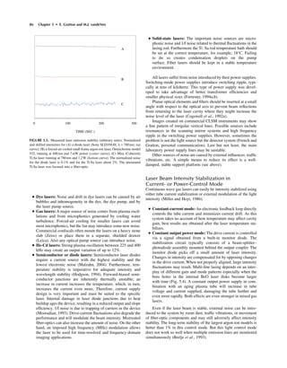
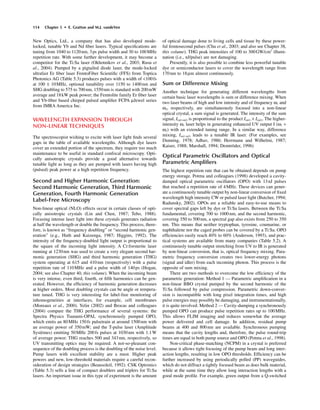
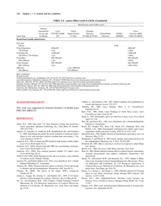
Principle of Operation
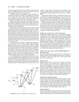
A particle of the active laser gain medium becomes excited when
it absorbs pump energy and goes to an excited level [Fig. 5.2(A)].
It then returns to the ground state via non-radiative relaxation
processes and also by emission of radiation [Fig. 5.2(B)]. Under
normal conditions, a Boltzmann equilibrium describes the popula-
tion of the various energy levels: the higher the energy level the
lower the population of that level. When an excited, metastable
level with a long lifetime exists in the laser medium, energy will
accumulate in this level. If the excitation is intense enough, the
Boltzmann distribution normally present will “invert” for the pop-
ulation of this metastable state (i.e., there will be many more elec-
tons in the excited state than Boltzmann would predict). In the laser
cavity, photons emitted from this energy level will strongly inter-
act with the population of the metastable level [Fig. 5.2(C)],
forcing it to release energy and return back to the lower level [Fig.
5.2(D)]. This process is called stimulated emission of radiation,
that is, the interaction of the light with the excited particle
increases the likelihood that the particle will return to the ground
state. The stimulated emitted light has a high degree of mono-
chromaticity, because emission occurs from a well-defined transi-
tion. In addition, the photon that results from this stimulated
de-excitation process is in phase with the electromagnetic wave
traveling in the laser medium. As a result, the emitted radiation has
excellent spatial and temporal coherence and is highly directional.
A convenient way to let the electromagnetic radiation interact
with the laser medium is a resonant cavity (Fig. 5.1). At optical
wavelengths, this is achieved by a Fabry–Perot type interferome-
ter. Two plane-parallel mirrors, one highly reflective, the other
semi-transparent, are separated by a distance equal to an integral
multiple of half the lasing wavelength. Because the electro-
magnetic radiation interacts repeatedly with the laser medium, this
resonant cavity increases the probability of stimulating de-
excitation. It also provides the necessary feedback to make the
emission grow coherently. Because the emission of the first photon
going in precisely the correct direction to reflect back and forth in
the cavity is a low probability event, getting the laser to fire is a
chaotic phenomenon that exhibits a threshold effect; lasers won’t
start or work stably below a certain output power level.
So far we have only discussed a three-level laser, that is,
ground-state, upper excited-state, and lower excited-state [Fig.
5.3(A)]. In a four-level laser [Fig 5.3(B)], as in the helium-neon
(He-Ne) laser, the population inversion can be obtained more
easily (Arecchi and Schultz-Dubois, 1972). The titanium–sapphire
(Ti:Sa) vibronic laser is effectively also a four-level laser due to
its broad energy bands (see later section). Other improvements
relate to the replacement of the Fabry–Perot mirrors by corner cube
reflectors or crossed-roof prisms to increase mechanical and
thermal stability. For further information, see Arecchi and Schultz-
Dubois, 1972; Stitch, 1979; Bertolotti, 1983; Bass and Stitch,
1985; Kudryashov and Weber, 1999; Webb and Jones, 2004;
Hodgson and Weber, 2005.
An interesting approach is the increasing use of optical fibers
that act as both lasing medium and cavity at the same time; a very
compact design is described later in this chapter.
Pumping Power Requirements
In order to sustain laser action, the gain of the optical resonator
needs to be larger than the losses due to resonator walls and other
optical elements. The minimum necessary pumping power, P, is
proportional to n3
. This means that, as one shifts from the infrared
(IR) through the visible (VIS) towards the ultraviolet (UV), an ever
increasing amount of energy is needed to obtain laser action. This
limits the possible pumping mechanisms.
Laser Modes: Longitudinal (Axial) and Transverse
• Axial or longitudinal modes: Separated by a distance, L, the
two plane-parallel mirrors of the Fabry–Perot interferometer
cavity form an optical resonator. This separation distance can
be long (meters, as in big frame ion lasers) or very small
(micrometers, as in very compact diode lasers). A number of
standing wave patterns each consisting of an integer multiple,
m, of half wavelengths, l/2, exists in an optical cavity of length
L: m = L/(l/2). The frequency, n, for the mth vibration along
the long axis of the laser is, therefore, n = mc/2L, where c is
the speed of light in the laser cavity. The frequency spacing
between adjacent longitudinal modes is c/2L, that is, the
inverse of the laser cavity round-trip time. A very large number
of longitudinal modes can exist in the laser cavity unless
bandwidth-limiting devices such as Fabry–Perot etalons are
installed in the cavity.
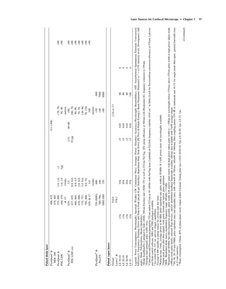
FIGURE 5.2. Optical (de)excitation processes. (A) Transition from ground
state to excitated state upon absorption of a photon, an electron moves to a
more outward shell, timescale < femtoseconds. (B) Relaxation to a lower level,
for example, ground state under spontaneous emission of a photon, electron
returns to a lower level, timescale nanoseconds. (C) Light driven interaction
inside laser gain medium of a photon with electrons in excited metastable state
with a long lifetime. (D) Stimulated coherent emission and light amplification.
FIGURE 5.3. Fast non-radiative relaxation processes couple an excited state
with a lower metastable energy level. Laser emission occurs in the gain medium
from the metastable state. Dependent on the gain medium properties this laser
process is described by a three-level or four-level lasing scheme.](https://image.slidesharecdn.com/pawley-handbookchapter5-170522204619/85/Pawley-handbook-chapter-5-5-320.jpg)


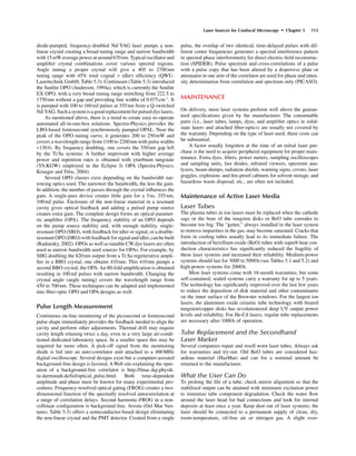
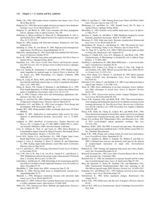
![92 Chapter 5 • E. Gratton and M.J. vandeVen
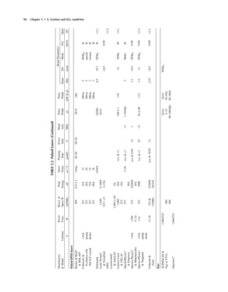
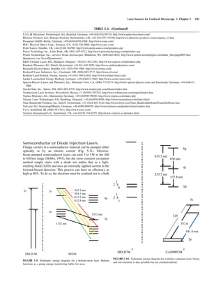
TABLE5.1.ContinuousWaveLasers(Continued)
ManufactoryLife&CWCWCWCWCWNoise&BeamParameters
&ModelPowerCons.Wave-lengthAv.PwrAv.PwrAv.PwrWave-lengthAv.PwrWave-lengthAv.PwrStabil.Diam.Div.ModePol.Qual.
(h)&(W)(nm)(mW)(mW)(mW)(nm)(mW)(nm)(mW)(rms,%)mmmradM2
Gaslasers:Argon-andKrypton-IonPureGasandMixedLaserSystems
Coherent70C-570C-K70C-300C-Sabre
Ionlasers1
ArgonKryptonSpectral308
Smallframe>5,000&MLUV5050351.1250275.4180
Water-cooled363.8250302.4380
70CInnova2
<40A/ph.MLB.G5,000MLUV750334.55000.5light1.50.5(Ar)TEM0
Series3phaseMMB.G6,000454.5140275.4–reg.0.8(Kr)
457.9300457.9560305.51,600
465.87030465.8180300.3–(3long
472.2100472.2240335.83,000term)
476.5600100476.5950351.11,800current
488.01,500250488.02,400363.81,700reg.
496.5600496.5950333.6–363.8
501.7350501.74807,000
300C-308<55A/ph514.52,000250514.53,2000.21.8@*0.4@TEM0
Smallframe3phase520.8130520.8454.5800514.5514.5
Water-cooled528.7300528.7550457.91,500
530.9130465.8800<2.6<0.8
Largeframe<70A/ph568.2150ML-VIS8,000472.21,300
Water-cooled3phaseML-VIS8,000476.53,000
SabreDBW253
B488.08,000
DualBrewsterMLRed750496.53,000
Window(DBW)MLwhite2,500501.71,800
orTunable647.1500250514.510,000
SealedMirrors676.4120528.71,800
(TBM)752.530ML
VIS25,000
Coherent&>5,000h457.980<0.75<1.3<0.8TEM0V<1.2
EnterpriseII<31A488200]6pp100:1
–6104
1phase514.5350
Water-cooledMLVIS1,000
LASOSLaser454.5–40<10.66<1.05TEM00V<1.3
&Argon-ion5
514.5500:1
SpectraPhysics<20A45840mW<0.10.69<0.95TEM00V<1.2
&Advantage6
488alllines<1pp100:1
163Caircooled514](https://image.slidesharecdn.com/pawley-handbookchapter5-170522204619/85/Pawley-handbook-chapter-5-15-320.jpg)


![106 Chapter 5 • E. Gratton and M.J. vandeVen
volume (Fig. 5.12), but to a stack of very thin layers forming mul-
tiple quantum wells (MQW), or planes of quantum wires or dots
(superlattice). Due to the small confined volume a high radiative
efficiency exists as well as a low lasing threshold. Most devices
still operate in NIR but the trend is to develop diode lasers using
wide bandgap materials that have an output below the red. Blue
diode lasers based either on ZnSe or doubling 860nm light, emit
at around 430nm and are about to enter the commercial market.
At higher power levels (Figueroa, 2002), direct frequency-
doubling in the diode laser forms an alternative route to the blue
region. For example, the D3
(Direct Doubled Diode laser, Coher-
ent) delivers 10mW at 430nm. When selecting a drive current
source, it is important to select one with a low noise, good stabil-
ity, and including a temperature controller on the diode laser head.
Diode lasers can change their emission wavelength over a limited
range (10–20nm) by varying their drive current and junction tem-
perature (Hodgson, 1994). The approximate tuning rate is about
0.1nm /°C. Cooling brings the lasing wavelength down. Beam
quality suffers from astigmatism that has to be optically corrected
(Snyder and Cable, 1993). Edge emitters now provide high power,
up to several watts CW in NIR.
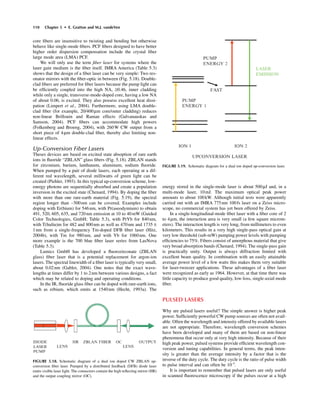
Semiconductor lasers are very appealing because they are
small [Fig. 5.13(B)], highly efficient, easy to use, and relatively
cheap. Integrated fiber-optic output is another feature available
from many manufacturers [Fig. 5.13(A)]. However, it should be
stressed that this small package comes with important special
requirements. The devices can be rapidly destroyed if both current
transients or nanosecond current spikes at start-up and internal
heating are not kept under control by the power supply electron-
ics. Static discharges (SD) from a person or an ungrounded sol-
dering iron, or the use of solder that is too hot or remains in contact
for too long may instantly destroy the laser. A mechanical shunt-
ing device (Unger, 1994) may prevent SD damage during han-
dling. Alternating current (AC) line filters are recommended
(Hodgson, 1994). This market is strongly driven by the digital
video disk (DVD) and audio compact disk (CD) industry where
the goal is to increase information storage densities. Most, if not
all, of the following examples are also wavelength stabilized by
stacks of multi-layer coatings usually deposited at the HR side and
producing bandpass filter reflectivity only for the lasing wavlength
[Fig. 5.14(B,C)]. Combining a proper OC coating with a fiber
pigtail having an inscribed Bragg grating has the same stabilizing
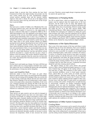
effect.
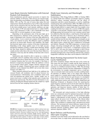
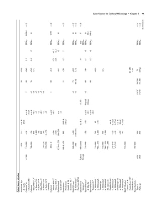
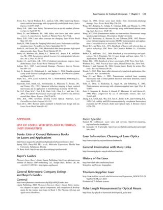
CONDUCTION
BAND
VALENCE
BAND
BANDGAP, EBG
> ª kT
STIMULATED EMISSION
FIGURE 5.11. Schematic energy diagram for a semiconductor laser. It is
based on laser emission from a forward biased p-n junction when driven by a
well-regulated drive current.
METAL
OXIDE
p-TYPE
lasing channel
n-TYPE
SUBSTRATE
METAL
~ 500 mm
< ~ 1 mm
FRONT AREA
~ 100 x 100µm
ELLIPTICAL
OUTPUT
INDEX-GUIDED DOUBLE HETERO-JUNCTION
EDGE EMITTING FABRY-PEROT TYPE
SINGLE-STRIPE DIODE LASER (FRONT VIEW)
CLEAVED AND
POLISHED FACES
ACTING AS
RESONATOR MIRRORS
FIGURE 5.12. Dimensions and cross-section through an edge emitting diode
laser. The polished sides act as highly reflecting mirror and output coupling
mirror. Thermo-electric cooling to remove heat is required.
2 mm LASER DIODE
LASER DIODE WITH
DBR FIBER OPTIC PIGTAIL
CIRCULAR BEAM ELLIPTICAL, COLLIMATED BEAM
WITH WITH
ANAMORPHIC OPTICS ASTIGMATISM CORRECTING OPTICS
A B
C
FIGURE 5.13. Example of (A) optional pigtail fiber-optics, (B) physical
dimensions of a diode laser, and (C) corrective optics to create a circular beam
profile.](https://image.slidesharecdn.com/pawley-handbookchapter5-170522204619/85/Pawley-handbook-chapter-5-29-320.jpg)
![Laser Sources for Confocal Microscopy • Chapter 5 107
Violet and Deep Blue Diode Lasers
Because these lasers produce 10mW of deep blue emission
(395–440nm) from an input power of less than 10W, they do not
require water cooling. Compare this with an argon-ion laser pro-
ducing the same 10mW from 1kW of electrical input, gallons of
cooling water per minute, and filling a good part of a laser table.
Most of the diode lasers have a single fixed-wavelength, which may
vary somewhat (see above under FBG Wavelength Stabilization).
Violet 405nm (Photonic Products Ltd., Table 5.3) lasers efficiently
couple into 3mm core single-mode fibers. Diode lasers presently
operate at 395 to 440nm (LG Laser Technologies GmbH,
Coherent; Table 5.3), 415 and 430nm (Crystal Laser Inc.), 440nm
(PicoQuant model LDH 440, Power Technology Inc.), 457nm
(Melles Griot), and 473nm (Crystal Laser Inc., Power Technology
Inc.). But they are not nearly as cheap as laser-pointers! Prices
range from a few thousand to US$25,000, depending on complex-
ity and features such as thermo-electric cooling.
Visible and Red Diode Lasers
488nm Diode Lasers An alternative to the argon-ion laser has
appeared in the form of the Protera 488 system from Novalux Inc.
(Table 5.3). Listed advantages over the argon-ion laser include
twice the life expectancy (20,000h), 1% of the power consump-
tion, up to 20mW output power, 2% of the size, 0.2% rms noise
level, and built-in thermo-electric Peltier cooling with conductive
heat removal via the enclosure. The ChromaLase 488 from Blue
Sky Research has a typical power consumption of 2W and output
power from 1 to 25mW output and creates 488nm laser light by
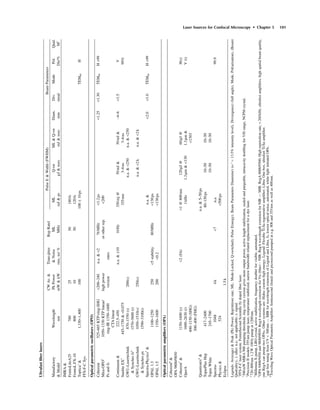
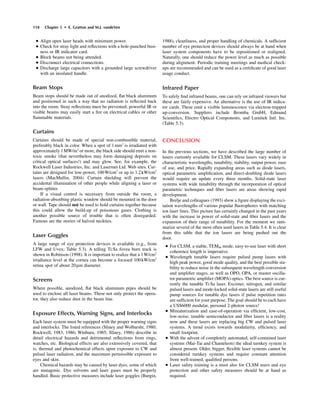
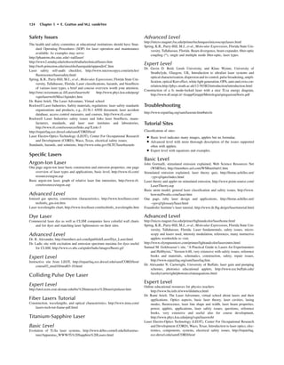
FREQUENCY SELECTING BRAGG GRATING INTEGRATED IN ACTIVE MEDIUM
DISTRIBUTED FEEDBACK (DFB) DIODE LASER
GRATING LENS AR OC
HR COATING
EXTENDED CAVITY DIODE LASER (ECDL)
REFLECTOR COUPLER GAIN SECTION
PHASE ADJ. SECTION
DISTRIBUTED BRAGG REFLECTOR (DBR) DIODE LASER
A
B
C
FIGURE 5.14. Diode lasers with wavelength tunability via an angle-
adjustable grating in an extended cavity configuration (A); improved mechan-
ical and thermal stability as well as wavelength and intensity control via a
bandpass reflective filter formed by a stack of thin coating layers (Bragg
grating). When the grating is incorporated into the gain medium the device is
a distributed feedback (DFB) diode laser (B), otherwise it is a distributed Bragg
reflector (DBR) diode laser. For ultrafast pulsed operation semiconductor sat-
urable absorber (SESAM) layers can be added to the high reflecting mirror
stack or to the saturable output coupler (SOC) to the output coupling face. Edge
emitting diodes require corrective optics because the emission is elliptic.
SHG doubling of ~980nm IR light. Similar specifications are
found for the Starbright 488, 10mW pumped at 40W (Torsana
Laser Technologies A/S); the BluePoint 488 at 2 to 5mW from
Rainbow Photonics AG; and the tunable 488nm laser from Toptica
Photonics AG. Coherent introduced the Sapphire (NOT to be
confused with a Ti:Sa system). It is a VECSEL GaAs diode laser
consuming 30 to 60W (mostly in the thermo-electric cooler),
optically pumped at 976nm, and intra-cavity frequency-doubled to
provide 20mW of electrical input.
The Novalux Inc. Protera is based on an ECSEL design with
a three-mirror folded cavity for better mode control and uses a
KNbO3 doubling crystal inside the laser cavity.
491nm Diode Lasers Some designs are based on up-conversion
of a fiber laser to produce 10mW at 491nm (Guided Color Tech-
nologies and Lumics GmbH). Others use a different principle. The
DPSS Dual Calypso laser (Nordborg and Karlsson, 2004) from
Cobolt AB (Table 5.3) offers 491nm at 20mW and 532nm at
50mW simultaneously. It uses a periodically polled potassium tita-
nium oxide phosphate (KTP) crystal, partly inside the laser cavity,
for non-linear optical frequency conversion. The 491nm line stems
from sum frequency mixing of Nd:YVO4 with the 1064nm line
from the Nd:YAG laser. Four hundred fifty-seven and 1340nm
lines can be added using similar methods. This laser has a noise
level of <0.3% and can directly replace the argon-ion laser oper-
ating at 488 and 514nm.
606 and 635nm Diode Lasers The He-Ne 594nm orange and
the red 632.8nm lines can be replaced by the 606nm (orange)
VECSEL Eksel 110 diode laser (Toptica PhotonicsAG; Häring and
Gerster, 2003) and the ChromaLase 635 25mW (Blue Sky
Research). The Radius 635nm CW 25mW (Coherent) has a
16-h beam pointing stability of about 60mrad compared with
~160mrad for a 17mW He-Ne. A 637nm red diode laser He-Ne
laser substitute has been incorporated into the Bio-Rad Radi-
ance2100CLSM (currently Carl Zeiss CellScience Ltd.).
685nm Diode Laser A 685nm 30mW CW diode laser is offered
by Lasos Laser Technik GmbH.
Recent Developments in Diode Lasers
In this expanding field, many features are rapidly improving to the
benefit of the user.
Emerging Tunability By incorporating a diode laser into an
external cavity equipped with a tunable grating (a Littman-Metcalf
cavity) wavelength tunability from 632.5 to 1630nm within a
50–150 GHz bandwidth is now available (New Focus; Table 5.3;
Scifres, 1994). These devices are listed as external or extended
cavity diode lasers [ECDL; Fig. 5.14(A)]. A narrow-line width
version has been described in Day and Dessau (1994). Although
for the moment manufacturers seem to focus on single wavelength
devices, mechanical and thermal stability should not be compro-
mised.
Beam Quality and Delivery Diode lasers typically require
extensive astigmatic and anamorphic corrective optics to obtain
a circular, parallel beam [Fig. 5.13(C)]. Other methods include
using a spatial filter or a single-mode fiber-optic as well as beam
homogenizers, such as the monolithic V-step design by Ingeneric
GmbH (Table 5.3), arrays of symmetrically arranged lenslets, the
so-called “fly’s-eye” lenses or light integrators (Homburg et al.,
2003), available, for example, from Limo Lissotschenko Mikroop-](https://image.slidesharecdn.com/pawley-handbookchapter5-170522204619/85/Pawley-handbook-chapter-5-30-320.jpg)
![108 Chapter 5 • E. Gratton and M.J. vandeVen
tik GmbH (Table 5.3). Optical elements, called graded index
(GRIN) lenses, have also been introduced to eliminate spherical
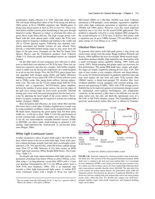
aberration in an elegant way (Carts, 1994). The vertical-cavity,
surface-emitting semiconductor laser (VCSEL; Fig. 5.15), is a
semiconductor laser with good circular-pattern beam quality
(Cunningham, 1993). Power levels are now reaching 100mW with
a wall-plug efficiency of 20%, high temperature stability, and good
beam quality.
Output Power and Cooling Output power has been increased
by building diode lasers as banks or arrays but these often require
additional water cooling that adds to their complexity. Quasi-CW
output levels can reach 300mJ and 1.5kW peak power. Tens to
100s of watts of CW power and long lifetimes are becoming
common. Cooling requirements depend on the output power gen-
erated and they range from passive air cooling via thermo-electric
(Peltier) cooling to water cooling, the latter often using microchan-
nels for optimum control of the junction temperature.
Temperature Tuning There is no longer a need to have a large
number of different diode lasers nor a large collection of emssion
filters for CLSM. Sivers and colleagues (2004) showed that,
with a 3mW low-power superlattice (multi-quantum well) 635nm
diode laser attached to a Bio-Rad MRC600 CLSM, many cell
stains that absorb in a broad range around 640nm can be reached
by cryogenically cooling the laser down to -196°C. This caused
the emission wavelength to shift linearly ~25nm down, while the
output power went up about five times. For equal fluorescence
signal, the noise level in the image caused by reflected laser light
decreased five times because it was possible to optimize the laser
wavelength to the optical filters more precisely.
Output Modulation Another important feature of semiconduc-
tor lasers is that their output can easily be modulated to well
above 100MHz and some can reach tens of gigahertz. This makes
them prime candidates for use in frequency-domain fluorescence
lifetime imaging microscopy (FLIM; see Chapter 27, this
volume).
Diode- and Lamp-Pumped Solid-State Lasers
A second class of solid-state lasers includes those using
neodymium yttrium aluminum garnet (Nd-YAG) and lasing in the
IR at 1064.2nm with very high fracture resistivity and good
thermal conductance (Fig. 5.16); Yttrium lithium fluoride (Nd-
YLF) with low thermal lensing (Arrigoni, 2004b); Nd-BaYF with
better subpicosecond generation and amplification properties;
yttrium orthovanadate lasing at 1064.3nm having a lower lasing
threshold than Nd-YAG (Kaminskii, 1981); GdVO4 lasers and
Nd:LuVO4, also having a lower lasing threshold. All of the mate-
rials listed above are pumped by FBG diode lasers [Fig. 5.14(C)].
Nd-YAG and Nd-YLF provide high overall efficiency and the good
beam quality necessary for frequency doubling to the visible pro-
ducing lines at 532 and 523nm. Microchip lasers are formed by
sandwiching laser and frequency doubling crystals into a millime-
ter size compact structure. Due to their small size they benefit from
ceramic laser materials with high thermal conductivity (Wisdom
and Digonnet, 2004).
A simpler design is possible with ytterbium tungstate
(Yb:KGW) absorbing between 900 and 1000nm that can be
directly pumped by a red diode laser.
Early models used flash lamp or CW krypton lamp pump
sources but the latest models tend to be equipped with a diode laser
[diode-pumped solid-state lasers (DPSS); Hobbs, 1994]. The
advantages of diode lasers over conventional pump sources, such
as lamps, are reduced cooling requirements because of higher effi-
ciencies due to a collimated and focused output, a perfect match
of pump-source emission wavelength with the absorption spectrum
of the lasing medium, and enhanced frequency stability (Baer,
1986). A typical improvement in electrical-optical conversion effi-
ciency is from 0.5% (TEM00 mode) to 6%.
CIRCULAR CROSS-SECTION
OUTPUT
METAL CONTACT
p-TYPE DBR OC
MQW LASING LAYERS
n-TYPE DBR HR
SUBSTRATE
METAL CONTACT
MULTI-QUANTUM WELL (MQW)
VERTICAL CAVITY SURFACE EMITTING LASER DIODE (VCSEL)
40 mm
3 mm
0.2 mm
5 mm
FIGURE 5.15. Dimensions and layout of a vertical cavity semiconductor
diode laser (VCSEL). Stacks of thin coating layers form the distributed Bragg
reflector (DBR) highly reflective mirror (HR) and the output coupling mirror
(OC). The emission pattern is circular and can be near-Gaussian.
4
I
9/2
4
I
11/2
4
F
3/2
4 4
S , F
3/2 7/2
4 4
F , H
5/2 9/2
730 nm 800 nm 1064 nm
3+ 3+
Nd : YAG and Nd :YVO4
FIGURE 5.16. Schematic energy diagram for a neodymium–yttrium–
aluminum garnet (Nd-YAG) laser and a neodymium–yttrium orthovanadate
(Nd:YVO4) laser.](https://image.slidesharecdn.com/pawley-handbookchapter5-170522204619/85/Pawley-handbook-chapter-5-31-320.jpg)
![The infrared output at 1064 (Nd-YAG) or 1054nm (Nd-YLF)
is easily frequency-doubled, tripled, or quadrupled with appropri-
ate non-linear crystals such as lithium triborate (LBO) and beta
barium borate (BBO) to provide radiation at 532 and 527nm
(SHG), 355 and 349 (THG), 266 and 262nm [fourth harmonic gen-
eration (FHG)], respectively. BBO even allows generation of the
fifth harmonic at 213nm. The stability of these lasers is very good
and the green emission wavelength is ideal for the excitation of
rhodamine dyes or for pumping the tunable solid-state lasers
described below. Nd-YAG also has lower-gain wavelengths at
1440, 1320, and 946nm, which when doubled provide 720, 660,
and 473nm. Power levels sufficient to obtain frequency doubling
create a blue laser suitable to replace the ion laser lines. Argon-ion
514nm emission can be replaced with a frequency-doubled
532nm DPSS design when the mode and beam characteristics are
optimized. A 473nm DPSS laser (CrystaLaser Inc. and National
Laser Corp. with 5–10mW, Table 5.3) is created by intracavity-
KNbO3 doubling the 946nm IR light of a diode-pumped Nd:YAG
laser. Typical cost is about US$8000.
As a pump source, the 514nm line of a large frame argon-ion
lasers may well be replaced with a frequency-doubled VersaDisk-
515 laser from Electronik Laser Systems GmbH (Table 5.3) emit-
ting, depending on the model, 2.5 to 15W of 515nm light in a
small footprint without water cooling, and improving the Ti:Sa
pump efficiency by 20% compared with the more common 532nm
DPSS pump source. Several companies now offer DPSS systems
in kit form. Examples are the DPSS educational kit from Optron-
ics Technologies S.A. and the Nd:YVO4 and Nd:YAG kits with
Cr:YAG SESAM from ALPHALAS GmbH. These lasers are
extremely compact, stable, and efficient with good beam quality
and offer turn-key operation. Electrical power requirements are
low: tens of watts. Beam quality can be improved with Gaussian
resonator mirrors and phase plates (Casperson, 1994).
Thin Disk Lasers
Very intense lines with much reduced thermal lensing and bire-
fringence can be generated by thin disk lasers. Radial thermal
effects are most severe in the rod-type lasing materials used in the
original Nd-YAG designs. Slab-type designs largely lift this
thermal problem. Scientific designs are profitting from Yb:YAG or
similar based thin disk systems such as the VersaDisc by Elec-
tronik Laser Systems GmbH, which can attain tens to hundreds of
watts of output power with minimal heating effects. It is based on
a 100mm thin disk of Nd:YAG, Yb:YAG, or other material bonded
to a heat sink and optically pumped on the opposite side. Because
the heat gradient is almost perfectly planar (i.e., parallel to the
bonding surface), the thermal lensing strongly present in high-
power, rod-type media is drastically reduced along with the
amount of birefringence. Optical aberrations are not introduced.
As the disk is small and thin, a special mechanical mirror arrange-
ment makes the pumplight impinge on it many times. Lasers such
as the VersaDisk currently deliver up to about 100W CW at
1030nm and about 15W at 515nm (Hitz, 2004a).
Tunable All Solid-State Laser
The release of the CW titanium-sapphire laser was an important
event (Hammerling et al., 1985). These lasers can be pumped
by a CW ion, Nd-YLF, Nd-YAG, or diode laser. Because their
vibrational-electronic levels are spread in a broad band, laser
transitions can take place over a wide range, and, given the right
mirrors, the tuning range extends from 700 to 1000nm (Fig. 5.17).
Power output is 3.5W at 790nm when pumped with an 18W Nd-
Laser Sources for Confocal Microscopy • Chapter 5 109
YVO4 or 20W all-line argon-ion laser. The Ti:Sa laser has virtu-
ally replaced the IR dye lasers; it is much easier to operate, no dyes
have to be changed, and the long-term stability is better than 3%
due to the elimination of flowing dye. The RMS noise between
10Hz and 2MHz is less than 2%, a factor of about 10 less than
for dye lasers. The main characteristics of these systems are the
generation of short pulses of about 100fs (FWHM), and high peak
power for frequency-doubling to the blue and near-UV spectral
range and for use in two-photon CLSM. Several configurations
have appeared resembling either CW ring or standing-wave dye
lasers. To cover the complete spectral range of this laser, special
mirror sets are required.
A similar wide-tuning range and high average power is offered
by the Alexandrite laser (Cr3+
in BeAl2O4 host), which covers the
730 to 826nm region when pumped CW at room temperature. This
laser can also be flash lamp pumped. The Forsterite laser (Cr4+
ions
in a Mg2SiO4 host material) emits between 1167 and 1345nm and
can be used in the 1200 to 1250nm tissue penetration window.
Its three main pumping bands are centered around 350 to 550, 600
to 850, and 850 to 1200nm. Both CW and pulsed models are
available. Its second harmonic is tunable from 600 to 650nm
(Mortensen, 1994). Liu and colleagues (2001) report multi-photon
femtosecond excitation of plant tissue at about 1250nm with a
Cr:forsterite laser (see also Chapter 21, this volume). Potential
members of this family of tunable solid-state lasers are the LiSAF
laser (Cr in LiSrAlF6) with a tuning range from 780 to 1060nm
and a peak emission at 825nm (Perry et al., 1993), and the LiCAF
laser (Cr in LiCaAlF6) tunable from 720 to 840nm. Tunable UV
could be created by Ce:LiSAF (Anderson, 1994b).
Continuous Wave Fiber Lasers
and Up-Conversion
Confusingly, fiber-coupled lasers in which a fiber-optic merely
guides the emission are also called fiber lasers. Although also
capable of generating a white continuum, micro-structured pho-
tonic crystal fiber (PCF) laser delivery systems should not be clas-
sified as fiber lasers. Unlike single-mode fibers, highly multi-mode
2
T
2
2
E
660 – 1180 nm
3+
Ti VIBRONIC LASER
PUMP
ENERGY
FIGURE 5.17. Schematic energy diagram for the Ti:Sa four-level vibronic
laser.](https://image.slidesharecdn.com/pawley-handbookchapter5-170522204619/85/Pawley-handbook-chapter-5-32-320.jpg)


![types of corrosion (Schneider and Williams, 1993). Do not use tap
water for cooling. Many laser and temperature bath manufacturers
now offer closed-loop laser cooling systems. Heat removal with
air-to-liquid cooling is also possible (Goldman, 1993). For proper
operation of a Nd-YAG laser, the resistivity of the cooling water
should be in the range recommended by the manufacturer. When
the resistivity is too low, the lamps will not start. If it is too high,
the plating on the inside of the elliptical resonator will dissolve
and cause a decrease in laser power. Water filters and de-ionizing
filters should be replaced regularly as demanded by the perfor-
mance of the laser. Stacked diode laser arrays, small in size but
with several tens of watts of optical output power, require liquid
cooling with micro-channel technology or thermo-electric (Peltier)
cooling.
External Optics
All optical surfaces should be kept as clean as possible. Mirror sur-
faces exposed to UV radiation will have to be replaced regularly,
depending on the impinging power density. Coatings may peel off.
Apertures in spatial filters should be inspected and replaced when
damage (burn) occurs. Fiber-optics, especially the ones exposed to
high-intensity UV light, may develop color centers, which result
in increased absorption and, in the end, failure of the entrance
section. High-intensity visible or infrared light may lead to over-
heating at the input fiber tip. Fortunately, the length of most fibers
is sufficient to allow them to be cut back, repolished, and recon-
nectorized, though sometimes at substantial cost and time delays.
If they are bent too tightly, fibers will break, causing a sudden loss
of output power. Pigtail fibers attached to the main body of a laser
diode may dislodge themselves. Due to the automated fabrication
process, which includes angular positioning to optimize the output
and to use the most intense emission spot, manual reattachment
usually does not re-establish the original power level. Laser
damage thresholds for dielectric mirrors and anti-reflective coat-
ings are roughly 250MW/cm2
at 532nm and 500MW/cm2
at 1064
nm, assuming surfaces are spotless and clean (Aubourg, 2002).
TROUBLESHOOTING
A very extensive and instructive body of information for gas, dye,
and diode laser maintenance, including optics cleaning and repair,
exists in Sam’s Laser FAQ (see Web site listings).
SAFETY PRECAUTIONS
Laser hazards include thermal and fire, acoustic shockwave, and
strongly wavelength-dependent photochemical damage. Types of
beam exposure are direct exposure intrabeam, specular, and diffu-
sion reflection effects. Eyes and skin are most commonly affected.
Non-beam–related hazards include electrical shock, capacitors,
hose leakage, water vapor condensation, air contaminants, fumes,
aerosols with biological agents, cadmium and zinc telluride (that
burns in the presence of high laser intensity and oxygen), radia-
tion damage, fire, compressed gases, gas cylinders, earthquake
damage, excimer gases, and laser dyes.
All lasers are generally divided into four classes:
Class 1. Embedded lasers and laser systems
Laser completely enclosed, radiation not accessible during use.
Class 1M. Lasers and laser systems:
CW = <40mW blue and = <400mW red.
Very low power: Safe for long-term intrabeam viewing.
Class 2. Low power visible lasers and laser systems:
CW = <1mW.
Low power level. Safe for brief accidental naked eye direct expo-
sure with blink and aversion response active.
Class 2M. Low-power visible lasers and laser systems.
Low-power visible collimated or divergent large beam diame-
ters. Potential hazard with magnifiers
Class 3R. Visible. Low-power lasers and laser systems.
Accidental exposure usually not hazardous but eye injury possible
upon intentional long-term viewing. Training required. Equivalent
to Class IIIA “danger” [Center for Devices and Radiological
Health (CDRH)] and ANSI 3a (USA).
Class 3R: Invisible. Low-power lasers and laser systems.
Wavelength dependent, limits are five times those of Class 1.
Class 3B. Medium-power lasers and laser systems:
CW = <500mW.
Serious eye injury even for brief accidental exposure to direct
beams possible. Training required.
Class 4. High-power lasers and laser systems.
Even diffuse and certainly direct-eye exposure will lead to serious
eye and skin injury. Poses fire hazard as well. Training required.
with M: magnifying instruments and R: relaxed requirements.
Limiting values for small point-like lasers with angular retinal spot
size smaller than 1.5mrad.
General safety precautions that become more stringent with
increasing classification, must be followed when operating a laser
[International Commission of Non-Ionizing Radiation Protection
(ICNIRP) and International Electrotechnical Commission (IEC)
60825-1 guidelines, see revised ANSI-Z-136.3 1996 classification,
safe use of lasers; Tozer, 2001; Schulmeister, 2003; Sliney, 1994;
LIAand Rockwell Laser Industries Inc.; Table 5.3]. Separate photo-
chemical and thermal retinal exposure limits, including limits for
damage from ultrashort, <1ns pulses, have been added as well as
the *.M classes. Every laboratory should have a Laser Safety
Officer (LSO) who should be consulted when necessary. This
person should be responsible for the proper training of users of
laser-assisted equipment. Safety training videos are available from
LIA, OSHA, and Rockland Laser Industries (Table 5.3) and often
also from your own local university. Outside the laser laboratory,
a “laser in use” warning sign must be posted and a red warning light
should be positioned at the entrance to the laser room.
Inside the laser laboratory, safety precautions are necessary
even for users of enclosed systems attached to CLSMs whenever
the system is opened or when the fiber-optics are aligned and expo-
sure to a laser beam becomes a possibility.
A brief “Do and Don’t” list:
• Inform everybody near the laser setup to be worked on. Check
the sign-up agenda.
• Check and put all required accessory equipment on the ready.
• Have the entrance warning red light on when any laser is on.
• Remove everybody from the laser site whose presence is not
required.
• Close the access doors.
• Close curtains.
• Remove rings, watches, and ties.
• Put safety goggles on.
• Never look directly into any laser beam.
Laser Sources for Confocal Microscopy • Chapter 5 117](https://image.slidesharecdn.com/pawley-handbookchapter5-170522204619/85/Pawley-handbook-chapter-5-40-320.jpg)


This document is an excerpt from the Handbook of Biological Confocal Microscopy, which discusses various aspects of laser sources used for confocal microscopy. It covers the basic principles of how lasers operate and their key properties like monochromaticity, coherence and beam quality. The document then describes different types of lasers including gas lasers, solid-state lasers and pulsed lasers. It discusses parameters like output power, wavelength and beam stability. Safety considerations for working with lasers are also outlined.