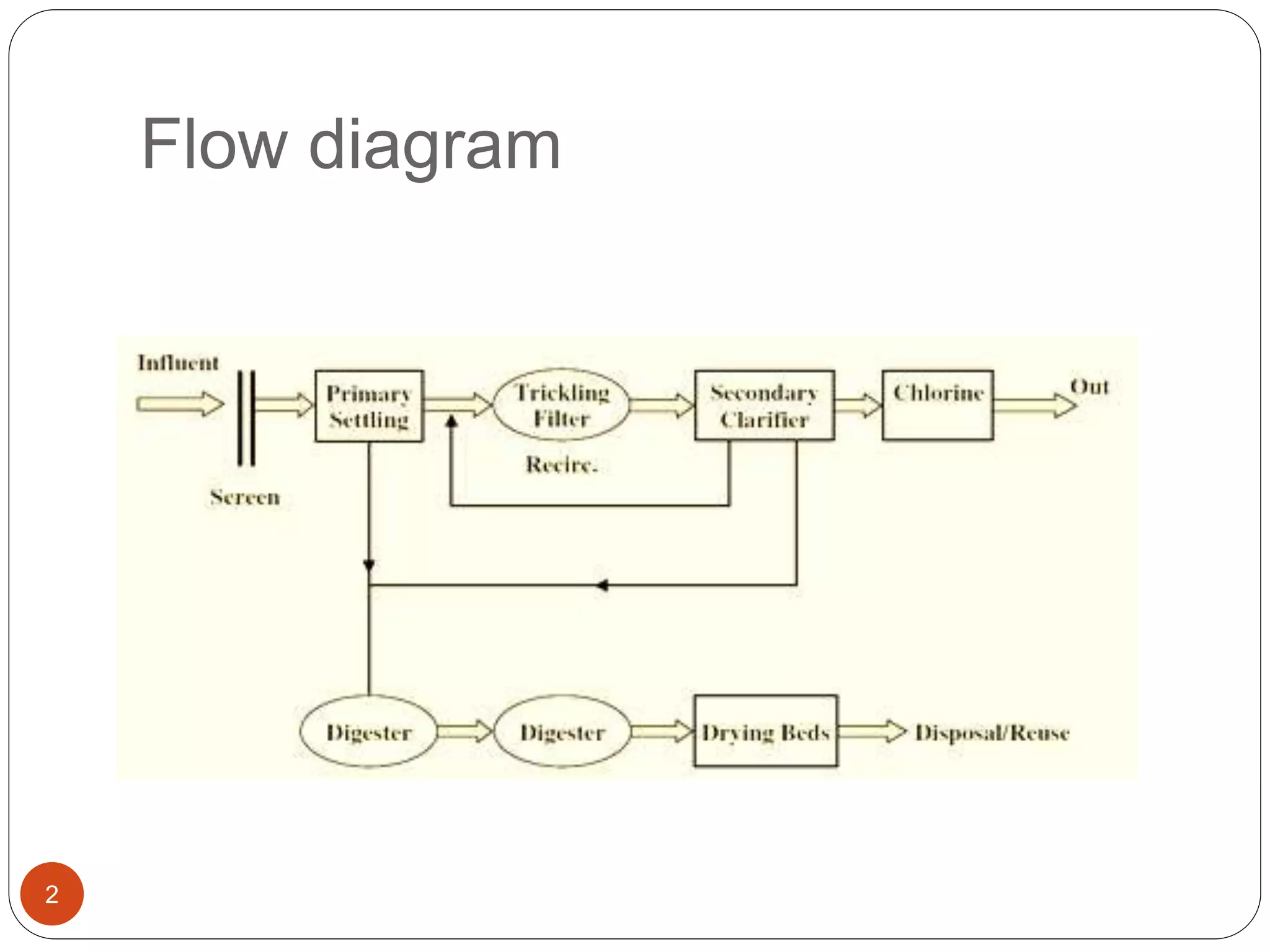
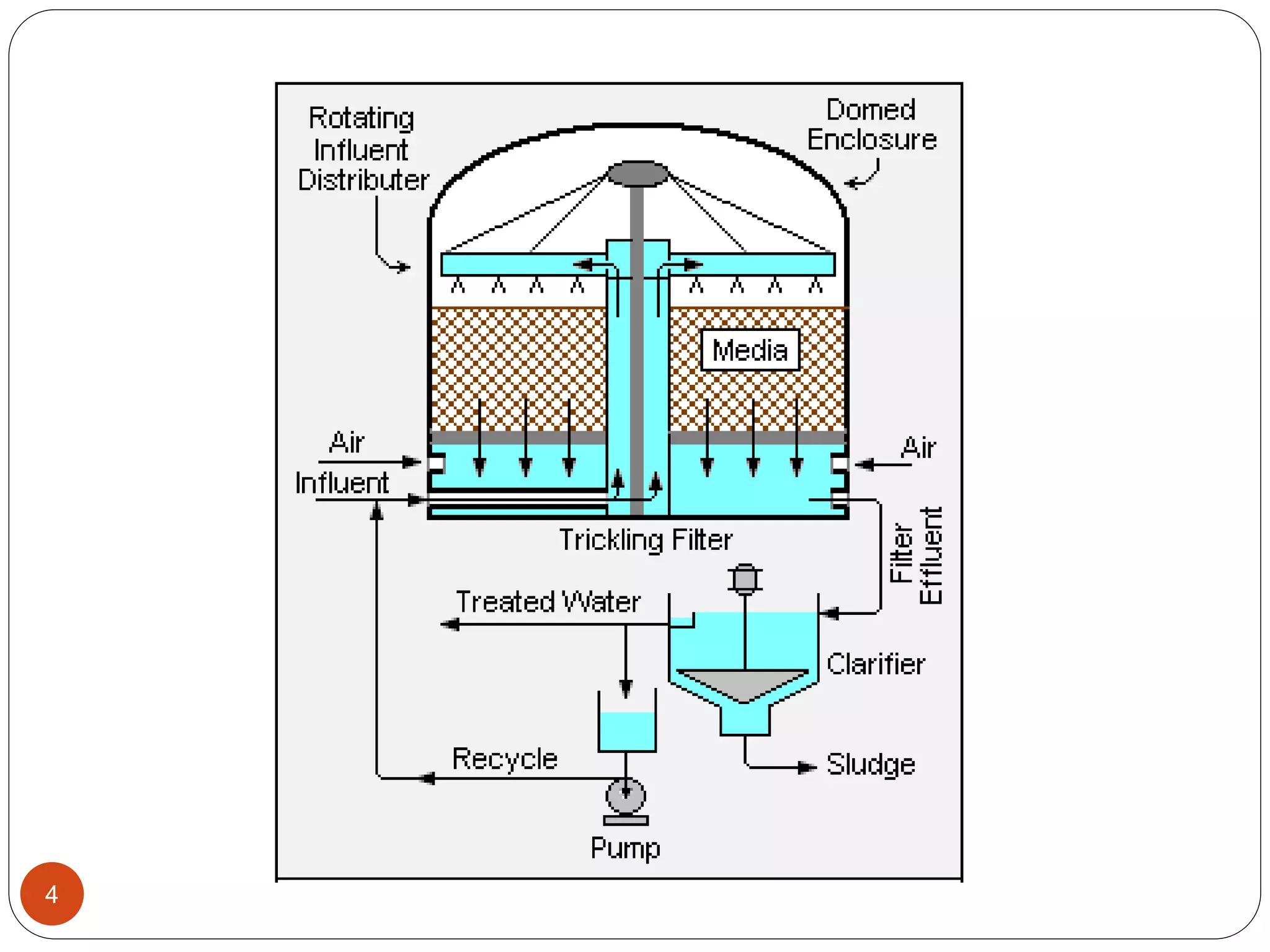
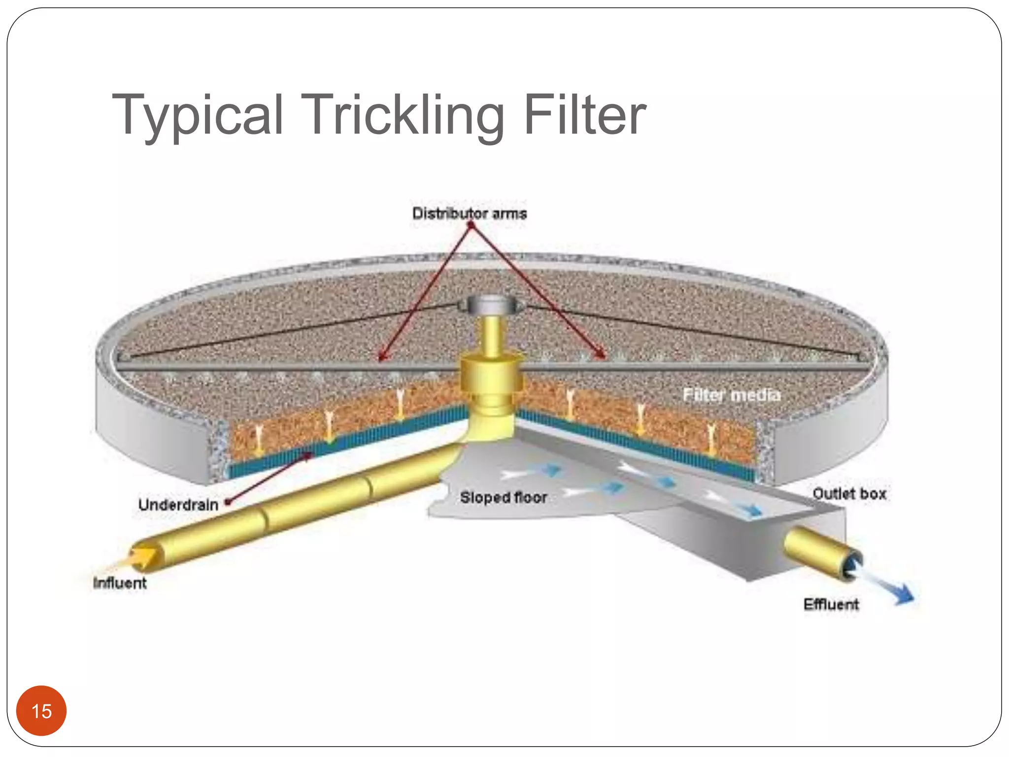
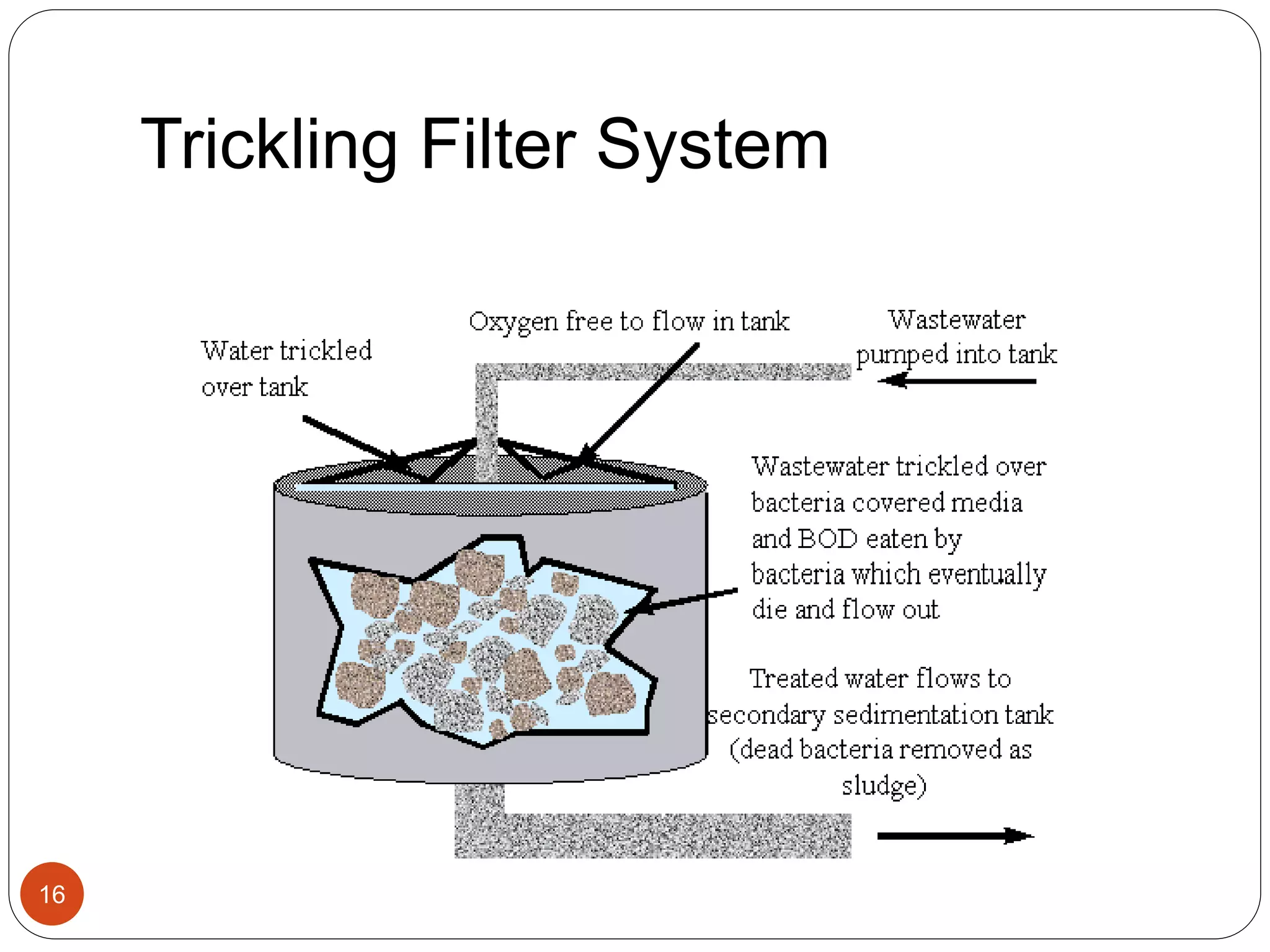
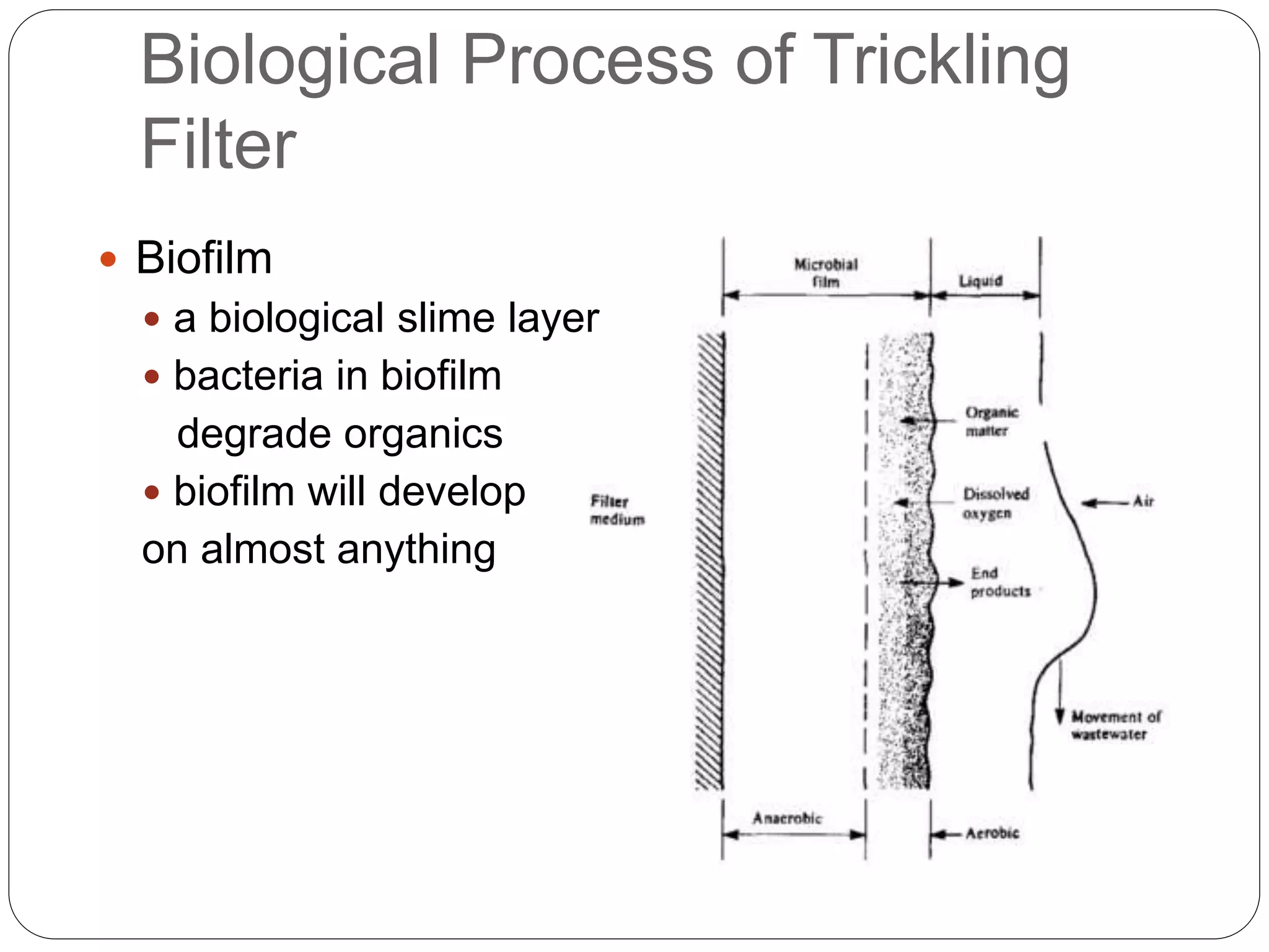
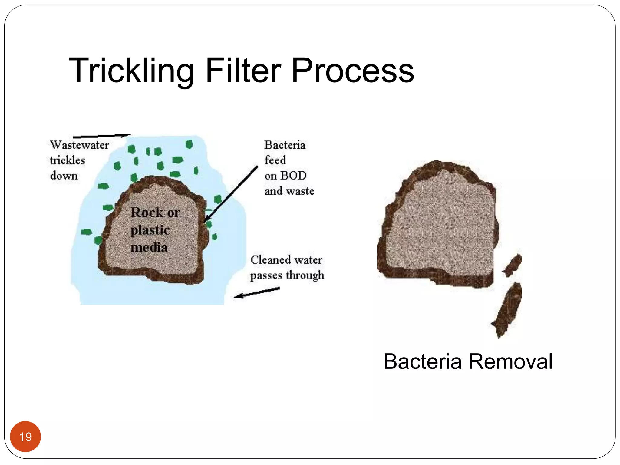
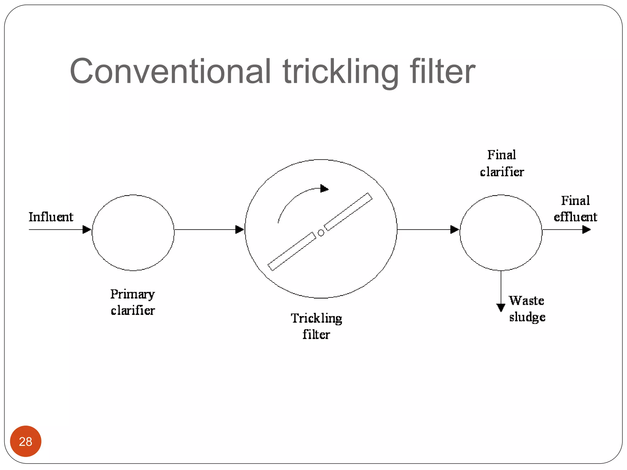
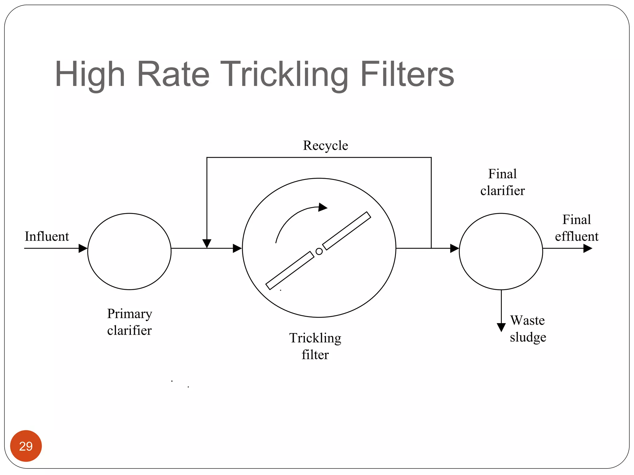
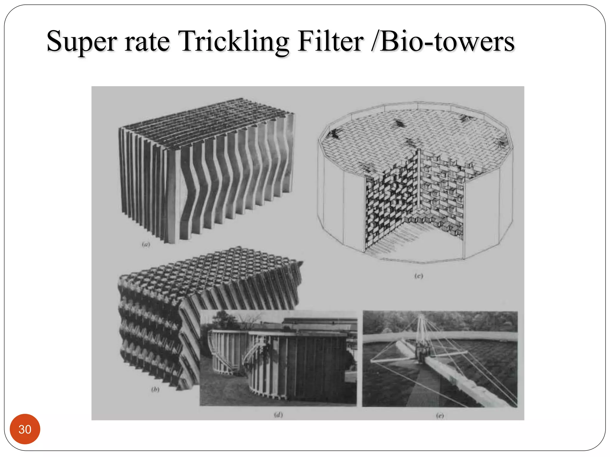
TRICKLING FILTER
1
Flow diagram
2
Trickling Filter
3
 Trickling filter is an attached-growth aerobic type
of process in which microorganisms attached to a
medium are used for removing organic matter
from wastewater.
 These reactors are also called as non-submerged
fixed film biological reactors.
 These are also called percolating filters or
sprinkling filters
 A trickling filter, is a tank of media such as gravel,
Stone Ballast or plastic material.
 Wastewater is distributed over the top of the
media and flows downward across the media
surface in a thin film.
 It then exits the bottom of the tank and flows into
4
Tricking Filter- Filter media
5
 Trickling filter uses packing medium composed of
crushed stone, slag, rock or plastic over which
wastewater is distributed continuously
 The ideal medium should have the following
properties: high specific surface area, high void
space, light weight, biological inertness, chemical
resistance, mechanical durability, and low cost.
 Coarser materials broken stone, blast furnace slag
Size vary from 25-75mm
 Should be washed before placing
 Required hardness -12 in brinell’s hardness testing
machine and should have a minimum crushing
strength of 100N/mm2
 Media placed in layers
 Depth of filter 1.8-3m
Filter media
6
 Can use plastic media
 lighter - can get deeper beds (up to 12 m)
 reduced space requirement
 larger surface area for growth
 greater void ratios (better air flow)
 less prone to plugging by accumulating slime
Typical Modular and Random Packed Plastic Media
Schematic diagrams of modular and random packed media used
in fixed-film treatment systems (Source: Bordacs and Young, 1998)
7
Random Packing
8
Structured Media
Rotary arms
9
Rotating Arms
10
 Rotate around central support by force of reaction
on sprays/electric motor
 Rate of revolution 2 RPM for small distributors
 ½ RPM for large distributors
 More than 2 arms
 Advantages for the rotation action
 Hepls in reduction of shock loads
 2 arms only working during low flow
 Rotary arms are kept 15-20 cm above the top
filtering surface
Dosing of sewage
11
 Rotary arms dose continues
 Spray nozzles are present in which the sewage is
dosed for 3-5 min and then rest for 5-10min
 Dosing tank for filter with distributors designed for
 1-3 min detention time for smaller capacity
 5-10 min detention time for higher capacity
Under drains
12
 Taking the effluent to
the effluent pipe
 Sloped
 Only filled 50% so
that helps in aeration
Trickling Filter-Working
 The wastewater in trickling filter is distributed over the
top area of a vessel containing non-submerged packing
material.
 Air circulation in the void space, is either natural draft or
blowers, provides oxygen for the microorganisms
growing as an attached biofilm.
 During operation, the organic material present in the
wastewater is metabolised by the biomass attached to
the medium.
 The biological slime grows in thickness as the organic
matter abstracted from the flowing wastewater is
synthesized into new cellular material.
 The thickness of the aerobic layer is limited by the depth
13
Trickling Filter-Working
14
 The micro-organisms near the medium face loose
their ability to cling to the media surface due to the
increase in thickness.
 The liquid then washes the slime off the medium
and a new slime layer starts to grow.
 This phenomenon of losing the slime layer is called
sloughing.
 The sloughed off film and treated wastewater are
collected by an under drainage which also allows
circulation of air through filter.
 The collected liquid is passed to a settling tank
used for solid- liquid separation.
 Some water is recycled to the filter, to maintain
moist conditions
Typical Trickling Filter
15
Trickling Filter System
16
Biological Process of Trickling
Filter
 Biofilm
 a biological slime layer
 bacteria in biofilm
degrade organics
 biofilm will develop
on almost anything
Biofilm
18
Trickling Filter Process
19
Bacteria Removal
Performance
 Power Required is less per unit BOD removal
 Suspended solids reduced by 90%
 BOD reduced to about 80-90 %
 BOD less than 20 ppm
20
Advantages and disadvantages
Advantages Disadvantages
21
 Rate of Filter loading is high
as required less land areas
and smaller quantities of filter
media for their installations.
 Effluent obtained from the
trickling filter is nitrified and
stabilized.
 Working of Trickling filter is
simple and does not require
any skilled supervision.
 They are flexible in
operation.
 They are self cleaning
 Mechanical wear and tear is
 The head loss through
these filters is high.
 Construction cost is high
 These filters cannot treat
raw sewage and primary
sedimentation is must.
 Operational troubles like
fly nuisance and odour
nuisance may prevail.
Operational Troubles in TF
22
 Filter Ponding
 Filter Flies
 Odour
 Icing for Filter Surface
Operational Troubles in TF
23
 Filter Ponding
 If the voids in the media get plugged, flow can collect
on the surface in ponds.
 Excessive sloughing, excessive organic loading, non-
uniformity in size of media and improper functioning of
primary treatment units are its chief causes.
 Remedies
 Wash the filter surface with a stream of water under high
pressure.
 Dose the filter with heavy applications of chlorine.
 Take the filter out of service for a period of one day or
longer to allow it to dry out.
Operational Troubles in TF
24
 Filter Flies
 primary nuisance insect- tiny, gnat-size filter fly,
or Psychoda. Filter flies develop most frequently
in an alternately wet and dry environment.
 Remedies:
 Dose filter continuously, not intermittently.
 keep orifice openings clear
 apply insecticides to filter walls
 dose filter with chlorine
 keep weeds and tall grass cut around filter
Operational Troubles in TF
25
 Odour Problem
 The presence of “rotten egg” odour is an indication of
anaerobic condition.
 Remedies
 Maintain aerobic conditions in all units, including settling tanks
and waste water system.
 Recirculate to filters.
 Icing for Filter Surface
 Cold weather not only reduces the efficiency of trickling
filters by decreasing the activity of the microorganisms, but
in severe cases actually can cause the wastewater to
freeze on the medium surface.
 Remedies
 decrease recirculation to the filter (influent is usually warmer
than recycled flows)
 construct wind screens
 operate two-stage filters in parallel rather than in series
Types of Trickling Filter
26
 Conventional Trickling Filter/Low Rate TF
 single stage rock media units
 loading rates of 1-4 m3 wastewater/m2 filter cross-
sectional area-day
 large area required
 High Rate Trickling Filter
 single stage or two-stage rock media units
 loading rates of 10-40 m3 wastewater/m2 filter
cross-sectional area-day
 re-circulation ratio 1-3
Types of Trickling Filter
27
 Super rate/ Biotower
 Synthetic plastic media units
 Modules or random packed
 Specific surface areas 2-5 times greater than rock
 Much lighter than rocks
 Can be stacked higher than rocks
 Loading rates of 40-200 m3 wastewater/m2 filter
cross-sectional area-day
 Plastic media depths of 5-10 m
Conventional trickling filter
28
High Rate Trickling Filters
Recycle
Primary
clarifier
Trickling
filter
Final
clarifier
Waste
sludge
Final
effluent
Influent
29
Super rate Trickling Filter /Bio-towers
30
Design Criteria for Trickling Filters
Table 10.5
Typical Design Criteria for Trickling Filters
Item Low-rate filter High-rate filter Super-rate filter
Hydraulic loading (m3
/m2
-d) 1 - 4 10 - 40 40 - 200
Organic loading (kg BOD5/m3-d) 0.08 - 0.32 0.32 - 1.0 0.8 - 6.0
Depth (m) 1.5 - 3.0 1.0 - 2.0 4.5 - 12.0
Recirculation ratio 0 1 - 3 1 - 4
Filter media Rock, slag, etc. Rock, slag,
synthetics
Filter flies Many Few, larvae are
washed away
Few or none
Sloughing Intermittent Continuous Continuous
Dosing intervals < 5 min < 15 s Continuous
Effluent Usually fully
nitrified
Nitrified at low
loadings
Nitrified at low
loadings
31

7. Trickling Filter.pptx

  • 1.
  • 2.
  • 3.
    Trickling Filter 3  Tricklingfilter is an attached-growth aerobic type of process in which microorganisms attached to a medium are used for removing organic matter from wastewater.  These reactors are also called as non-submerged fixed film biological reactors.  These are also called percolating filters or sprinkling filters  A trickling filter, is a tank of media such as gravel, Stone Ballast or plastic material.  Wastewater is distributed over the top of the media and flows downward across the media surface in a thin film.  It then exits the bottom of the tank and flows into
  • 4.
  • 5.
    Tricking Filter- Filtermedia 5  Trickling filter uses packing medium composed of crushed stone, slag, rock or plastic over which wastewater is distributed continuously  The ideal medium should have the following properties: high specific surface area, high void space, light weight, biological inertness, chemical resistance, mechanical durability, and low cost.  Coarser materials broken stone, blast furnace slag Size vary from 25-75mm  Should be washed before placing  Required hardness -12 in brinell’s hardness testing machine and should have a minimum crushing strength of 100N/mm2  Media placed in layers  Depth of filter 1.8-3m
  • 6.
    Filter media 6  Canuse plastic media  lighter - can get deeper beds (up to 12 m)  reduced space requirement  larger surface area for growth  greater void ratios (better air flow)  less prone to plugging by accumulating slime
  • 7.
    Typical Modular andRandom Packed Plastic Media Schematic diagrams of modular and random packed media used in fixed-film treatment systems (Source: Bordacs and Young, 1998) 7
  • 8.
  • 9.
  • 10.
    Rotating Arms 10  Rotatearound central support by force of reaction on sprays/electric motor  Rate of revolution 2 RPM for small distributors  ½ RPM for large distributors  More than 2 arms  Advantages for the rotation action  Hepls in reduction of shock loads  2 arms only working during low flow  Rotary arms are kept 15-20 cm above the top filtering surface
  • 11.
    Dosing of sewage 11 Rotary arms dose continues  Spray nozzles are present in which the sewage is dosed for 3-5 min and then rest for 5-10min  Dosing tank for filter with distributors designed for  1-3 min detention time for smaller capacity  5-10 min detention time for higher capacity
  • 12.
    Under drains 12  Takingthe effluent to the effluent pipe  Sloped  Only filled 50% so that helps in aeration
  • 13.
    Trickling Filter-Working  Thewastewater in trickling filter is distributed over the top area of a vessel containing non-submerged packing material.  Air circulation in the void space, is either natural draft or blowers, provides oxygen for the microorganisms growing as an attached biofilm.  During operation, the organic material present in the wastewater is metabolised by the biomass attached to the medium.  The biological slime grows in thickness as the organic matter abstracted from the flowing wastewater is synthesized into new cellular material.  The thickness of the aerobic layer is limited by the depth 13
  • 14.
    Trickling Filter-Working 14  Themicro-organisms near the medium face loose their ability to cling to the media surface due to the increase in thickness.  The liquid then washes the slime off the medium and a new slime layer starts to grow.  This phenomenon of losing the slime layer is called sloughing.  The sloughed off film and treated wastewater are collected by an under drainage which also allows circulation of air through filter.  The collected liquid is passed to a settling tank used for solid- liquid separation.  Some water is recycled to the filter, to maintain moist conditions
  • 15.
  • 16.
  • 17.
    Biological Process ofTrickling Filter  Biofilm  a biological slime layer  bacteria in biofilm degrade organics  biofilm will develop on almost anything
  • 18.
  • 19.
  • 20.
    Performance  Power Requiredis less per unit BOD removal  Suspended solids reduced by 90%  BOD reduced to about 80-90 %  BOD less than 20 ppm 20
  • 21.
    Advantages and disadvantages AdvantagesDisadvantages 21  Rate of Filter loading is high as required less land areas and smaller quantities of filter media for their installations.  Effluent obtained from the trickling filter is nitrified and stabilized.  Working of Trickling filter is simple and does not require any skilled supervision.  They are flexible in operation.  They are self cleaning  Mechanical wear and tear is  The head loss through these filters is high.  Construction cost is high  These filters cannot treat raw sewage and primary sedimentation is must.  Operational troubles like fly nuisance and odour nuisance may prevail.
  • 22.
    Operational Troubles inTF 22  Filter Ponding  Filter Flies  Odour  Icing for Filter Surface
  • 23.
    Operational Troubles inTF 23  Filter Ponding  If the voids in the media get plugged, flow can collect on the surface in ponds.  Excessive sloughing, excessive organic loading, non- uniformity in size of media and improper functioning of primary treatment units are its chief causes.  Remedies  Wash the filter surface with a stream of water under high pressure.  Dose the filter with heavy applications of chlorine.  Take the filter out of service for a period of one day or longer to allow it to dry out.
  • 24.
    Operational Troubles inTF 24  Filter Flies  primary nuisance insect- tiny, gnat-size filter fly, or Psychoda. Filter flies develop most frequently in an alternately wet and dry environment.  Remedies:  Dose filter continuously, not intermittently.  keep orifice openings clear  apply insecticides to filter walls  dose filter with chlorine  keep weeds and tall grass cut around filter
  • 25.
    Operational Troubles inTF 25  Odour Problem  The presence of “rotten egg” odour is an indication of anaerobic condition.  Remedies  Maintain aerobic conditions in all units, including settling tanks and waste water system.  Recirculate to filters.  Icing for Filter Surface  Cold weather not only reduces the efficiency of trickling filters by decreasing the activity of the microorganisms, but in severe cases actually can cause the wastewater to freeze on the medium surface.  Remedies  decrease recirculation to the filter (influent is usually warmer than recycled flows)  construct wind screens  operate two-stage filters in parallel rather than in series
  • 26.
    Types of TricklingFilter 26  Conventional Trickling Filter/Low Rate TF  single stage rock media units  loading rates of 1-4 m3 wastewater/m2 filter cross- sectional area-day  large area required  High Rate Trickling Filter  single stage or two-stage rock media units  loading rates of 10-40 m3 wastewater/m2 filter cross-sectional area-day  re-circulation ratio 1-3
  • 27.
    Types of TricklingFilter 27  Super rate/ Biotower  Synthetic plastic media units  Modules or random packed  Specific surface areas 2-5 times greater than rock  Much lighter than rocks  Can be stacked higher than rocks  Loading rates of 40-200 m3 wastewater/m2 filter cross-sectional area-day  Plastic media depths of 5-10 m
  • 28.
  • 29.
    High Rate TricklingFilters Recycle Primary clarifier Trickling filter Final clarifier Waste sludge Final effluent Influent 29
  • 30.
    Super rate TricklingFilter /Bio-towers 30
  • 31.
    Design Criteria forTrickling Filters Table 10.5 Typical Design Criteria for Trickling Filters Item Low-rate filter High-rate filter Super-rate filter Hydraulic loading (m3 /m2 -d) 1 - 4 10 - 40 40 - 200 Organic loading (kg BOD5/m3-d) 0.08 - 0.32 0.32 - 1.0 0.8 - 6.0 Depth (m) 1.5 - 3.0 1.0 - 2.0 4.5 - 12.0 Recirculation ratio 0 1 - 3 1 - 4 Filter media Rock, slag, etc. Rock, slag, synthetics Filter flies Many Few, larvae are washed away Few or none Sloughing Intermittent Continuous Continuous Dosing intervals < 5 min < 15 s Continuous Effluent Usually fully nitrified Nitrified at low loadings Nitrified at low loadings 31