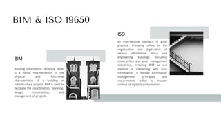
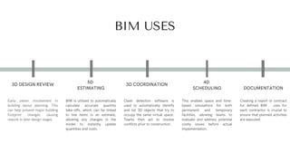
BIM
Standards
According to ISO 19650
Sarie Lababidi
Table Of Contents
List of Abbreviations
1.
BIM and ISO 19650
2.
BIM Uses
3.
BIM Maturity Levels
4.
BIM Life Cycle
5.
Common Data Environment (CDE)
6.
Level of Development vs. Level of Detail
7.
LOD Requirements
8.
Construction Operations Building Information Exchange (COBie)
9.
Industry Foundation Classes (IFC)
10.
BIM Execution Plan (BEP)
11.
Naming Convention
12.
List of Abbreviations
& Acronyms
BIM & ISO 19650
Building Information Modeling (BIM)
is a digital representation of the
physical and functional
characteristics of a building or
infrastructure project. BIM is used to
facilitate the coordination, planning,
design, construction, and
management of projects.
BIM
an international standard of good
practice. Primarily refers to the
organisation and digitisation of
various information about civil
engineering buildings (including
construction and asset management
industries), including BIM as one
method of interacting with such
information. It defines information
management principles and
requirements within a broader
context of digital transformation.
ISO
BIM USES
Early owner involvement in
building layout planning. This
can help prevent major building
footprint changes causing
rework in later design stages.
3D DESIGN REVIEW
BIM is utilized to automatically
calculate accurate quantity
take-offs, which can be linked
to line items in an estimate,
allowing any changes in the
model to instantly update
quantities and costs.
5D
ESTIMATING
Clash detection software is
used to automatically identify
and list 3D objects that try to
occupy the same virtual space.
Teams then act to resolve
conflicts prior to construction.
3D COORDINATION
This enables space and time-
based simulations for both
permanent and temporary
facilities, allowing teams to
evaluate and address potential
costly issues before actual
implementation.
4D
SCHEDULING
Creating a report or contract
for defined BIM uses for
each contractor is crucial to
ensure that planned activities
are executed.
DOCUMENTATION
BIM MATURITY LEVELS
Explanation of BIM development
Higher BIM maturity level in Bim improve project
efficiency through the alignment of processes and
adoption of standardized practices. It reduces
rework, accelerates timelines, and keeps projects
on budget.
Level 0:
No collaboration.
2D CAD drawings used for design.
Information shared through hard copies or
static files.
Level 1:
Partial collaboration.
Use of 3D modeling for visualization, alongside
2D documentation.
A CDE facilitates better data sharing.
Level 2:
Collaborative design and construction
workflows.
Federated models combine Structural BIM
Modeling, MEP BIM Modeling, and
architectural designs.
Level 3:
Full collaboration in a shared BIM environment.
Real-time updates across all disciplines.
Integration of 5D and 6D BIM for cost and
sustainability analysis.
BIM LIFE CYCLE
COMMON DATA ENVIRONMENT (CDE)
Common Data Environment: A combination of technical solutions and process workflows. It ensures
that information is carefully planned, shared, stored, managed and retrieved and that it is timely,
correct, complete, and consistent.
COMMON DATA ENVIRONMENT (CDE)
The CDE solution is implemented through a shared server or web portal. Autodesk construction cloud, Autodesk BIM 360, Google Drive, and Microsoft one
drive are some of the examples. The CDE is set up by the appointing party or the third party who is a service provider appointed by the appointing party.
CDE IN PRACTICE
The degree to which the element’s
geometry has been thought through.
Level of Development Level of Detail
How much detail is included in the
model element.
Level of Development vs. Level
of Detail
LOD Requirements
Elements are sufficiently developed to fully
convey the design intent for the represented
item.
A model element developed to the level of
shop drawings.
To define requirements for model elements
that are sufficiently developed to support
construction-level coordination.
Does not indicate a higher level than LOD
400, rather it indicates that the element’s
geometry is determined through observation
of an existing item rather than design of a
future item.
LOD 300 LOD 400
LOD 350 LOD 500
Symbols showing the existence of a
component but not its shape, size, or precise
location; or space reservation
volumes.
Elements are generic placeholders but are
recognizable as the components they
represent (e.g. a pump, a light fixture, a
beam, etc.)
LOD 100
LOD 200
The idea behind COBie is that the key information is all
pulled into one format and shared between the construction
team at defined stages in a project.
The basic principles of COBie are:
Classification
1.
Data Model—This makes integration with other
construction and design tools easier.
2.
Format— Choice between several delivery formats,
including spreadsheet.
3.
Construction
Operations Building
Information Exchange
(COBie)
This is information that would usually be extracted from the
specification and lists the types of products in the building,
their reference and contact information for the
manufacturer. Not shown is the “Attribute” worksheet; this
details the properties for each of the type objects
The data inside a
COBie spreadsheet
Industry Foundation Classes (IFC)
An IFC file, developed using
the Industry Foundation
Classes format, is a platform-
independent model file used in
Building Information Modeling
(BIM). It includes details like
spatial elements, materials, and
shapes of a building or facility.
According to ISO 19650, Using
the IFC schema, requirements
could be structured in a
machine-interpretable and
machinetestable manner.
Closed BIM is a method that
relies on proprietary formats
from specific BIM software,
requiring a team to use the
same software, and
sometimes the same version,
to exchange information
effectively.
Industry Foundation Classes (IFC)
Open BIM involves all
participants collaborating and
exchanging project
information using open, non-
proprietary formats,
Regardless of the BIM tools
and applications utilized.
BIM Execution
Plan (BEP)
Includes:
Roles and responsibilities
1.
Timeline for the project
2.
Deliverables that will be
produced.
3.
The BEP (BIM Execution Plan) is a
document that outlines
standardized workflows and
guidelines for strategic BIM
implementation on specific
projects.
BIM Execution Plan (BEP)
Define goals/
uses
Delivery
Strategy
Project
standards
Methods &
Procedures
Manage
responsibilities
Milestones,
Deliverables.
Capability
capacity
IT resources
Project
processes
Delivery Plan
Naming Convention
Based on ISO 19650
Example
For BIM Level 2, adhering to a mandatory naming convention is crucial for
regular data exchange across disciplines and organizations, and is essential
for project success.
Thank You.
Sarie Lababidi

BIM Standards( for BIM engineers and Coordinators

  • 1.
    BIM Standards According to ISO19650 Sarie Lababidi
  • 2.
    Table Of Contents Listof Abbreviations 1. BIM and ISO 19650 2. BIM Uses 3. BIM Maturity Levels 4. BIM Life Cycle 5. Common Data Environment (CDE) 6. Level of Development vs. Level of Detail 7. LOD Requirements 8. Construction Operations Building Information Exchange (COBie) 9. Industry Foundation Classes (IFC) 10. BIM Execution Plan (BEP) 11. Naming Convention 12.
  • 3.
  • 4.
    BIM & ISO19650 Building Information Modeling (BIM) is a digital representation of the physical and functional characteristics of a building or infrastructure project. BIM is used to facilitate the coordination, planning, design, construction, and management of projects. BIM an international standard of good practice. Primarily refers to the organisation and digitisation of various information about civil engineering buildings (including construction and asset management industries), including BIM as one method of interacting with such information. It defines information management principles and requirements within a broader context of digital transformation. ISO
  • 5.
    BIM USES Early ownerinvolvement in building layout planning. This can help prevent major building footprint changes causing rework in later design stages. 3D DESIGN REVIEW BIM is utilized to automatically calculate accurate quantity take-offs, which can be linked to line items in an estimate, allowing any changes in the model to instantly update quantities and costs. 5D ESTIMATING Clash detection software is used to automatically identify and list 3D objects that try to occupy the same virtual space. Teams then act to resolve conflicts prior to construction. 3D COORDINATION This enables space and time- based simulations for both permanent and temporary facilities, allowing teams to evaluate and address potential costly issues before actual implementation. 4D SCHEDULING Creating a report or contract for defined BIM uses for each contractor is crucial to ensure that planned activities are executed. DOCUMENTATION
  • 6.
    BIM MATURITY LEVELS Explanationof BIM development Higher BIM maturity level in Bim improve project efficiency through the alignment of processes and adoption of standardized practices. It reduces rework, accelerates timelines, and keeps projects on budget. Level 0: No collaboration. 2D CAD drawings used for design. Information shared through hard copies or static files. Level 1: Partial collaboration. Use of 3D modeling for visualization, alongside 2D documentation. A CDE facilitates better data sharing. Level 2: Collaborative design and construction workflows. Federated models combine Structural BIM Modeling, MEP BIM Modeling, and architectural designs. Level 3: Full collaboration in a shared BIM environment. Real-time updates across all disciplines. Integration of 5D and 6D BIM for cost and sustainability analysis.
  • 7.
  • 8.
    COMMON DATA ENVIRONMENT(CDE) Common Data Environment: A combination of technical solutions and process workflows. It ensures that information is carefully planned, shared, stored, managed and retrieved and that it is timely, correct, complete, and consistent.
  • 9.
    COMMON DATA ENVIRONMENT(CDE) The CDE solution is implemented through a shared server or web portal. Autodesk construction cloud, Autodesk BIM 360, Google Drive, and Microsoft one drive are some of the examples. The CDE is set up by the appointing party or the third party who is a service provider appointed by the appointing party.
  • 10.
  • 11.
    The degree towhich the element’s geometry has been thought through. Level of Development Level of Detail How much detail is included in the model element. Level of Development vs. Level of Detail
  • 12.
    LOD Requirements Elements aresufficiently developed to fully convey the design intent for the represented item. A model element developed to the level of shop drawings. To define requirements for model elements that are sufficiently developed to support construction-level coordination. Does not indicate a higher level than LOD 400, rather it indicates that the element’s geometry is determined through observation of an existing item rather than design of a future item. LOD 300 LOD 400 LOD 350 LOD 500 Symbols showing the existence of a component but not its shape, size, or precise location; or space reservation volumes. Elements are generic placeholders but are recognizable as the components they represent (e.g. a pump, a light fixture, a beam, etc.) LOD 100 LOD 200
  • 13.
    The idea behindCOBie is that the key information is all pulled into one format and shared between the construction team at defined stages in a project. The basic principles of COBie are: Classification 1. Data Model—This makes integration with other construction and design tools easier. 2. Format— Choice between several delivery formats, including spreadsheet. 3. Construction Operations Building Information Exchange (COBie)
  • 14.
    This is informationthat would usually be extracted from the specification and lists the types of products in the building, their reference and contact information for the manufacturer. Not shown is the “Attribute” worksheet; this details the properties for each of the type objects The data inside a COBie spreadsheet
  • 15.
    Industry Foundation Classes(IFC) An IFC file, developed using the Industry Foundation Classes format, is a platform- independent model file used in Building Information Modeling (BIM). It includes details like spatial elements, materials, and shapes of a building or facility. According to ISO 19650, Using the IFC schema, requirements could be structured in a machine-interpretable and machinetestable manner.
  • 16.
    Closed BIM isa method that relies on proprietary formats from specific BIM software, requiring a team to use the same software, and sometimes the same version, to exchange information effectively. Industry Foundation Classes (IFC) Open BIM involves all participants collaborating and exchanging project information using open, non- proprietary formats, Regardless of the BIM tools and applications utilized.
  • 17.
    BIM Execution Plan (BEP) Includes: Rolesand responsibilities 1. Timeline for the project 2. Deliverables that will be produced. 3. The BEP (BIM Execution Plan) is a document that outlines standardized workflows and guidelines for strategic BIM implementation on specific projects.
  • 18.
    BIM Execution Plan(BEP) Define goals/ uses Delivery Strategy Project standards Methods & Procedures Manage responsibilities Milestones, Deliverables. Capability capacity IT resources Project processes Delivery Plan
  • 19.
    Naming Convention Based onISO 19650 Example For BIM Level 2, adhering to a mandatory naming convention is crucial for regular data exchange across disciplines and organizations, and is essential for project success.
  • 20.