The document discusses several aerodynamic concepts related to lift, including:
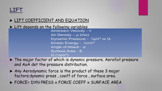
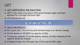
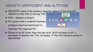
1. Lift depends on dynamic pressure, coefficient of lift, and wing area. It is generated by differences in pressure between the upper and lower wing surfaces.
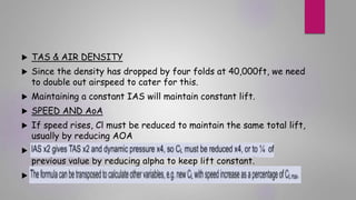
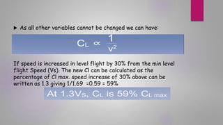
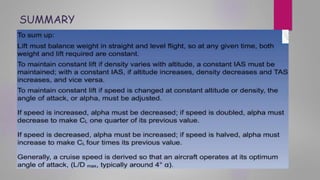
2. At higher altitudes, true airspeed must increase to compensate for lower air density in order to maintain the same lift.
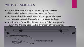
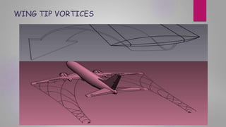
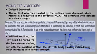
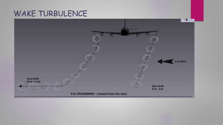
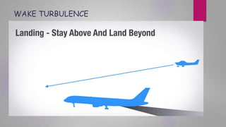
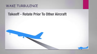
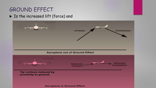
3. Wingtip vortices form due to pressure differences across the wing and induce downwash, reducing effective angle of attack and causing induced drag. They can be hazardous to following aircraft.
4. Ground effect reduces drag and increases lift when an aircraft is within one wingspan of the ground due to inhibition of wingtip vort