This document provides instructions for attaching datum tags to dimensions and datum planes in Creo models and drawings. The key steps include:
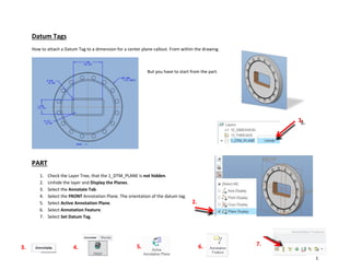
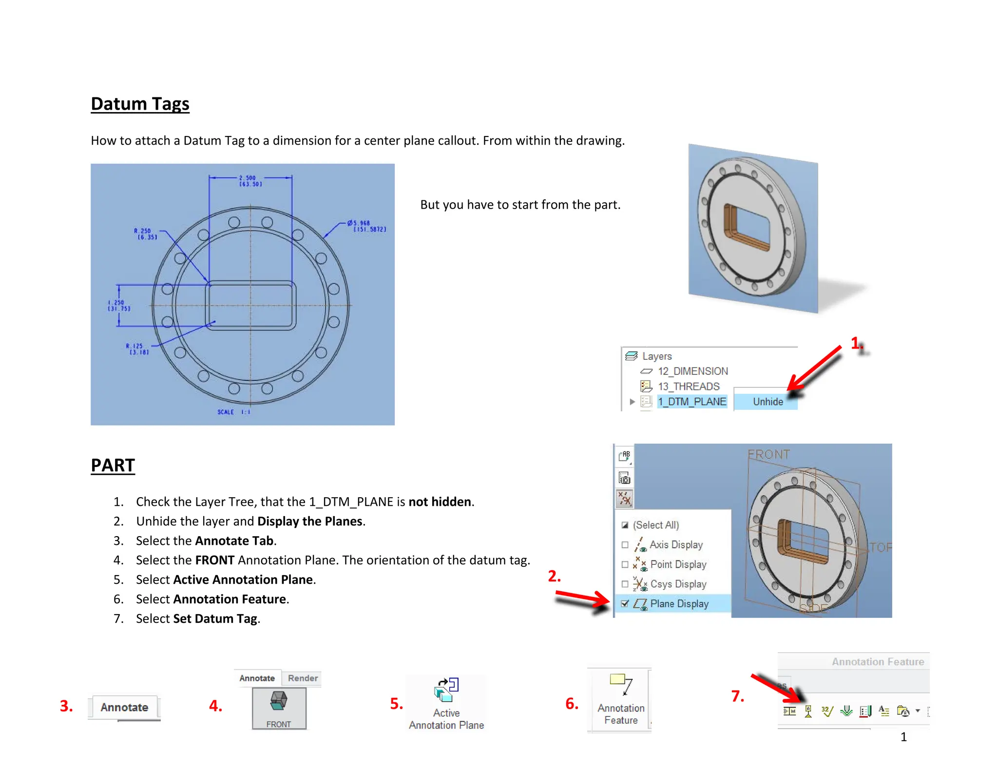
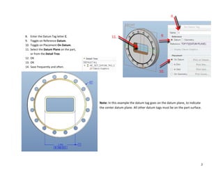
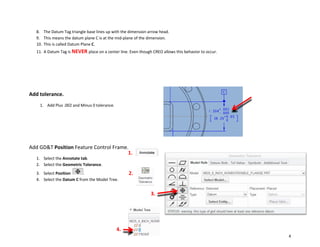
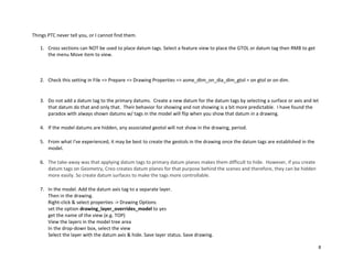
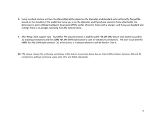
1. Adding datum tags to datum planes in the model by selecting the datum plane and setting the datum tag letter.
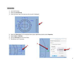
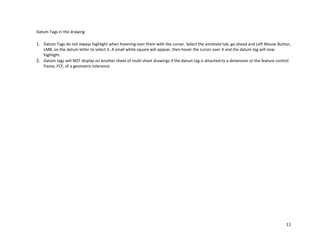
2. Placing datum tags on dimensions in drawings by selecting the dimension, picking the associated datum, and aligning the tag with the dimension leader line.
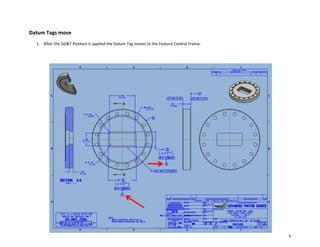
3. Moving datum tags attached to dimensions or geometric tolerances to follow those features between drawing sheets.
Proper use of datum tags helps indicate which datum plane a dimension or tolerance is referenced to. The document cautions against certain practices like placing tags on centerlines.