The Adaptation of Clay-Bath and hydro-cyclones in Palm Nut Cracked-Mixture Separation to Small–Scale Oil Palm Processing Industry

International Journal of Modern Engineering Research (IJMER) is Peer reviewed, online Journal. It serves as an international archival forum of scholarly research related to engineering and science education. International Journal of Modern Engineering Research (IJMER) covers all the fields of engineering and science: Electrical Engineering, Mechanical Engineering, Civil Engineering, Chemical Engineering, Computer Engineering, Agricultural Engineering, Aerospace Engineering, Thermodynamics, Structural Engineering, Control Engineering, Robotics, Mechatronics, Fluid Mechanics, Nanotechnology, Simulators, Web-based Learning, Remote Laboratories, Engineering Design Methods, Education Research, Students' Satisfaction and Motivation, Global Projects, and Assessment…. And many more.

Recommended
More Related Content
What's hot
What's hot (14)
Viewers also liked
Viewers also liked (20)
Similar to The Adaptation of Clay-Bath and hydro-cyclones in Palm Nut Cracked-Mixture Separation to Small–Scale Oil Palm Processing Industry
Similar to The Adaptation of Clay-Bath and hydro-cyclones in Palm Nut Cracked-Mixture Separation to Small–Scale Oil Palm Processing Industry (20)
More from IJMER
More from IJMER (20)
Recently uploaded
Recently uploaded (20)
The Adaptation of Clay-Bath and hydro-cyclones in Palm Nut Cracked-Mixture Separation to Small–Scale Oil Palm Processing Industry
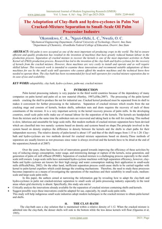
- 1. International Journal of Modern Engineering Research (IJMER) www.ijmer.com Vol. 3, Issue. 4, Jul - Aug. 2013 pp-2023-2026 ISSN: 2249-6645 www.ijmer.com 2023 | Page 1 Okoronkwo, C. A., 2 Ngozi-Olehi, L. C.,1 Nwufo, O. C. 1 Mechanical Engineering Department, Federal University of Technology, Owerri. Imo State 2 Department of Chemistry, AlvanIkoku Federal College of Education, Owerri. Imo State ABSTRACT: Oil palm is now accepted as one of the most important oil-producing crops in the world. The bid to ensure efficient and quality production has resulted in the invention of machines that have greatly reduced human labour in the production process. Separation of cracked mixture to recover the kernels is one of the most important activities in Palm Kernel oil (PKO) production process. Research has led to the invention of the clay-bath and hydro-cyclones for the recovery of kernels from the cracked mixture. However, these machines are very costly to install and operate and as well require skilled labour. This research work is intended to examine these innovations and recommend suitable adaptations of these machines for use by the small scale mill operators who cannot afford the modern machines and the technical know-how needed to operate them. The clay-bath has been recommended for local mill operators for cracked mixture separation due to its ease of use and scalability. KEY WORD: adaptability, clay bath, hydro-cyclones, palm-nut, cracked mixture I. INTRODUCTION Palm kernel processing industry is very popular in the third world countries because of the dependency of many companies on palm kernel and palm oil as raw material (Hartley, 1987),(Oke,2007). The processing of the palm kernel entails cracking the shell to produce the nut for industrial use. Cracked kernel produced must be separated from its shell to makes it convenient for further processing in the industries. Separation of cracked mixture which results from the nut cracking stage and consists of kernels, broken shells, unbroken nuts and dusts requires the recovery of each of these constituents of the mixture. It is a very important activity in the kernel recovery process of palm mills. In the developing countries, small scale palm mills make use of manual labour for the separation of the kernels. The kernels are handpicked from the mixture and at the same time the unbroken nuts are recovered and taking back to the mill for cracking. This method is slow, laborious and unsuitable for large scale mills. But modern methods of cracked mixture separation have been devised which are classified into two namely: systems based on density and systems based on shape.The principle involved in the system based on density employs the difference in density between the kernels and the shells to chart paths for their independent recovery. The relative density of palm kernel is about 1.07 and that of the shell ranges from 1.15 to 1.20. Clay- bath and hydro-cyclones are two methods devised for cracked mixture separations based on density.These methods of separation are usually known as wet processes since water is always involved and the kernels have to be dried at the end of the separation.(Amoah et al 2007) Over the years, there have been a lot of innovations geared towards improving the efficiency of these activities by way of reducing energy consumption, water usage, and minimizing damage or rupture of the kernels, noise generation, and generation of palm oil mill effluent (POME). Separation of cracked mixture is a challenging process especially to the small- scale mill owners. Large-scale mills have automated hydro-cyclone machines with high separation efficiency, however, clay- baths and hydro cyclones are known for their high energy and water consumption making their application in small-scale mills difficult(Poku, 2002). On the other hand, inefficient separation process could cause shells to be carried together with kernel to palm kernel expellers which could damage the crushing mechanisms. Therefore, the need to study these processes becomes imperative as a means of investigating the operations of the machines and their suitability in small-scale, medium- scale and large-scale palm mills. In this paper, the authors aimed at narrowing the information gap by revealing how to adapt the clay-bath and hydro-cyclones in palm nut cracked-mixture separation to small–scale oil palm processing industry especially in the rural areas where grid electricity is absent. Specifically, this study sets out to: Critically analyze the innovations already available for the separation of cracked mixture containing shells and kernels. Suggest possible ways these innovations could be adapted for use, especially, by small-scale palm mills. This study will help indigenous small scale industries adopt modern techniques in the cracked mixture to obtain palm kernel and shells. II. THE CLAY-BATH The clay-bath uses a clay solution that is maintained within a relative density of 1.12. When the cracked mixture is admitted into the clay-bath, the denser shells will sink to the bottom while the less dense kernels will float (Oguoma et al, 1993). The Adaptation of Clay-Bath and hydro-cyclones in Palm Nut Cracked-Mixture Separation to Small–Scale Oil Palm Processing Industry
- 2. International Journal of Modern Engineering Research (IJMER) www.ijmer.com Vol. 3, Issue. 4, Jul - Aug. 2013 pp-2023-2026 ISSN: 2249-6645 www.ijmer.com 2024 | Page III. GENERAL DESCRIPTION/OPERATION OF THE CLAY-BATH The clay-bath is made up of the bottom tank which is of cylindrical shape with portions of sloping rectangular section for the returning clay solution, the top conical chamber which is of inverted cone shape with inlet and outlet side openings for the clay solution, the cylindrical shaped expansion chamber which has a small inlet connected to the pump outlet pipe and large outlet connected to the top conical chamber inlet opening, the vibrating screen made of rectangular single deck type and supported by two steel leaf spring located at both side of the screen, an eccentric shaft driven byelectric motor via flexible rubber coupling used to create the vibrating motion, the stirrer connected with gear motor that is mounted on the bottom tank and extends right to the bottom of the tank, a gear motor used to reduce the speed of the stirrer to about 28rpm through a bevel gear arrangement, the circulating pump connected with electric motor which is of the centrifugal end suction type, a mechanical seal used in place of the gland packing with the pump that is driven by an electric motor via a v- belt drive. The electric motors are 1.5KW, 2.2KWand 7.5KW all 4 pole squirrel cage, 3 phase induction motor suitable for 230/415V, 50Hz electric supply for vibrating screen, circulating pump and the stirrer gear motor respectively. In this separator (clay-bath), the clay solution is circulated through the system by means of a pump. This pump draws solution from the bottom tank and pushes it to the top conical chamber through the expansion chamber. During operation, the cracked mixture enters the system from the top of the top conical chamber and flows along the solution. Kernel being lighter floats to the top of the solution and shells heavier than the solution sinks to the bottom of the chamber. They are carried along by the solution to the respective outlets and then to the vibrating screen which is partitioned to receive the kernel and the shell in separate compartments thus allowing the solution to flow through the stainless steel mesh and back to the bottom tank while kernel and shell are being screened and exit from the end of the screen, hence the clay solution is circulated and re-used. An inbuilt stirrer is used to homogenize the solution. It is necessary to top up the solution to make for the losses because little amount of the solution is usually carried away with the kernel and shell. Washing of the kernel ex-separator is possible by installing a clean water pipe to the end of the vibrating screen where small jets of water can be sprayed onto the kernel and wash them before exit from the screen. The clay-bath could be used domestically. A small cemented pit or a ground tank could be used for the clay-bath separator. The tank or pit will be filled with water and the clay will be added in the right proportion so that the density of the suspension is maintained. Manual stirring could be used to keep the clay in suspension, while the cracked mixture is poured into the pit or tank. The density difference will make the shells to sink and the kernels to float. The kernels can easily be skimmed off the surface of the suspension while the shells are evacuated later. Drying of the shells and nuts could be done under the sun on concrete floors or roofing sheets. This will increase the desiccation rate significantly. IV. PROBLEMS OF CLAY-BATH One of the problems associated with the clay-bath is that of maintaining the solution within the appropriate density range. Therefore, a solution of common saltof suitable density may be substituted for the clay suspension. This brine has the advantage that it does not settle out which ensures that the density results much steadier but must be topped up from time to time Maycock, (1990). Another problem that may likely arise from the use of this system is the disposal of water after using the clay bath. V. THE HYDROCYCLONE SEPARATOR A hydro cyclone assembly consists of two bottom cylindrical tanks with a conical base called baths, two overhead hydro cyclones called the kernel and shell hydro cyclones, two pumps, and two pairs of exit and overflow pipes. The size of the apertures at the bottom of the hydro cyclones is critical to their operation. The heights of the overflow pipes are adjustable as it is used to control the purity of the kernels. The cracked mixture from the cracker is admitted into cracked mixture bath which is already filled with water. The pump powered by an electric motor is used to pump the cracked mixture together with water into the kernel hydro cyclone. Figure 1: A diagram showing the cyclone action of a hydrocyclone. At the entry of the cracked mixture into the hydrocyclone, a helical motion is initiated by the tangential entry of the cracked mixture which causes the heavy particles to be thrown by centrifugal force to the wall of the cylinder and after tracing a helical path exits through the bottom of the cyclone. By choosing the dimensions of the hydrocyclone and the pressure of the pump correctly, most of the shell pieces pass downwards and out through the bottom cone with small proportion of water flow. The larger part of the water together with most of the kernel after taking part in an initial downward circular movement gradually move towards the centre of the cylinder and start moving upwards leaving the hydrocyclone via the overflow tube and exit pipe. In the kernel hydrocyclone, the high overflow pipe is used to ensure that the kernels entering are sufficiently pure and ready for bagging. This high setting also causes some kernels to move downwards and exit with the shells through the exit pipes. The mixture (containing
- 3. International Journal of Modern Engineering Research (IJMER) www.ijmer.com Vol. 3, Issue. 4, Jul - Aug. 2013 pp-2023-2026 ISSN: 2249-6645 www.ijmer.com 2025 | Page shells and little proportion of kernels) leaving the exit pipe of the kernel hydrocyclone is passed to another bath called the shell bath where a second pump is used to push the mixture to another hydrocyclone known as the shell hydrocyclone. The two baths are adjacent to each other with a perforated partition between them which allows the water levels to equalize. It is important to prevent the perforations from becoming so worn out that kernels can pass through into the shell fraction. In the shell hydrocyclone, the overflow pipe is lowered sufficiently so that kernels together with some shells are evacuated and sent back to the cracked mixture bath. The lower overflow pipe ensures that the down flow is cleaner hence only shells move through the exit pipe of the shell hydrocyclone. VI. SYSTEM BASED ON SHAPE Other method of nut/kernel separations are based on the shape of the shells and kernels. These include the winnowing column and the vibrating table. These methods are collectively called dry processes since they used either air or no fluid at all. VII. WINNOWING COLUMN OR PNEUMATIC SEPARATORS The winnowing column uses air as the fluid for separation;the column consists of tall cylindrical or rectangular steel duct that is connected to a blower or suction fan. The winnowing column is used in conjunction with either of the wet methods of separations- claybath or hydrocyclone. The commercial winnowingsystem uses force or induced draught (Halim, et al, 2009). Cracked mixture from the cracker is conveyed by a screw conveyor to some height along the winnowing column. As the mixture is poured inside the column, the air draught maintained by a suction pump sucks the fibres, dust and some shell pieces up the duct while the kernels, un-cracked nuts, and the remaining shells fall and are captured in another duct through the use of an air lock. In this way, up to about 30% to 40% of the shell present in the cracked mixture is removed without causing a loss exceeding 1% of the total kernel. This winnowed mixture is now dust free and can then be sent to the claybath or hydrocyclone separator. According to (Maycock,1990), it is necessary to adjust the air velocity in the separating column to a suitable value to ensure removal of light shell without losing kernel and this is usually found to be in the range of 12.5m/s to 15m/s. Recently, the four stage winnowing column has been invented and developed by the Malaysian Palm Oil Board (MPOB) in collaboration with Hur Far Engineering Works SdnBhd (HF) and FELDA Palm Industries SdnBhd (FPISB). These separation systems consist of a series of equipment: a four stage winnowing column, a cyclone, a blower fan, an air lock and an auger. Each column was designed with different parameters (e.g. air velocity, fan speed, column height, inlet outlet levels, feeding ratio, etc.) in order to achieve the desired shell and kernel ratio separation at each outlet point (Halim et al,2009). VIII. THE VIBRATING TABLE The vibrating table is a dry separation process. The table is supported by two steel leaf springs located at both sides of the table. An eccentric shaft driven by electric motor via flexible rubber coupling is used to create the vibrating motion. The cracked mixture from the cracker is poured on top of the table and as the table vibrates, the kernels are moved to one side of the table, while the shells move to the other side. IX. WAYS TO ADAPT THESE INNOVATION TO SUIT SMALL SCALE INDUSTRIES The small scale oil processing industries in the third world countries are mostly situated in the rural areas of the developing countries where grid electricity is mostly nonexistent or irregular. The cost of generating an alternative energy using diesel powered generators can be very enormous and will adversely affect the profit of such industries. Most industries have collapsed in Nigeria due to high running cost of using diesel generating power plants to run the machineries. Recall that the main source of energy to the clay- bath and the hydro cyclone separators is electricity generated using diesel powered generators. The cost of diesel in Nigeria is about $1.00 per litre. In a day, depending on the fuel economy of the generator, an average four cylinder engine consumes about 200litres of fuel in twelve hours. Since an average clay bath motor generatesabout 1.5-7.5kW of power a solar powered generator can replace the diesel powered generator and still produce the same amount of power. To adapt the claybath palm kernel separator to suit the small scale industries, solar powered generators can be used which will drastically reduce the energy cost for the processing of the palm kernel. Another way to reduce operational cost is to replace the bevel gear powered stirrer in the clay bath with a manual stirrer. Though the average stirring speed for the mechanical stirrer is 28rpm, a manual stirrer can produce this speed conveniently. When the stirrer is removed, the cost of installing the stirring system is drastically reduced because it will eliminate the gears used for speed reduction. The ground tank should be constructed in such a way that as to provide a draining chamber where spent water can be channeled into a confined chamber to avoid the degradation of the environment. X. CONCLUSION AND RECOMMENDATION Most families in south-east and south-south geographical regions of the Nigeria earn their income from the sales of palm oil and palm kernels. Some individuals and villages already have small- scale palm mills where modern machines are used for the stripping, digesting, pressing and cracking processes. However, the separation of cracked mixture to recover kernels from the cracked mixture still remains the main problem faced by small scale operators.The standard claybath requires enormous power due to electric motor used to power the pumps. However, the technology is easily understood even by local operators and can be easily adopted to suit them even domestically. The hydrocyclone requires more water and power than the claybath and the technology that is associated with hydrocyclone is more complex than that of the claybath,
- 4. International Journal of Modern Engineering Research (IJMER) www.ijmer.com Vol. 3, Issue. 4, Jul - Aug. 2013 pp-2023-2026 ISSN: 2249-6645 www.ijmer.com 2026 | Page hence its use by the rural dwellers will be difficulty. It is however recommended that small-scale palm industries adopt the use of clay-bath for crack mixture separation to reduce the laborioustask of handpicking and as well increase the speed of the process XI. APPENDIX 1. BOTTOM TANK 6. PUMP INLET VALVE 2. EXPANSION CHAMBER 7. GEAR DRIVE 3. TOP CONICAL CHAMBER 8. STIRRER 4. CIRCULATING PUMP 9. SHELL DISCHARGE PIPE 5. VIBRATING SCREEN 10. KERNEL DISCHARGE PIPE Figure 2: A schematic of the claybath A. CRACKED MIXTURE BATH E. SHELL HYDROCYCLONE B. SHELL BATH F. KERNEL SCREEN AND DRYER C. PUMP G. SHELL SCREEN D. KERNEL HYDROCYCLONE Figure 3: A schematic of the hydrocyclone Figure 4: Web shots of a hydrocyclone assembly. REFERENCES [1]. Amoah, J. y., Aggey, M., and Annumu, S. (2007): Cracked- Mixture Sieving Rates and Efficiencies In Small Scale Palm Nut Processing In Ghana. Ghana Journal of Science. [2]. Halim, R M; Bakar, N. A; Wahid, M B.; May C. Y; Ramli, Ridzuan; Ngan, Ma Ah; M, R(2009): Maximizing the Recovery of Dry Kernel and Shell via a Four Stage Winnowing Column. MPOB Information Series (MPOB TT No. 427). [3]. Hartley, C.W.S , (1987) The Project Of Oil Palm And The Extraction In The Oil Palm, Longman London [4]. Maycock, J. H., & Symposium on New Developments in Palm Oil.(1990). Innovations in palm oil mill processing and refining. Kuala Lumpur: Palm Oil Research Institute of Malaysia. [5]. Oguoma ,O.N,C.COnwuzuruigbo and Nnamadim(1993) Design of Palm kernel/shell separation for developing countries.Nig.J.Tech.Edu,10:1-2 [6]. OkeP.K(2007) “Development And Performance Evaluation Of Indigenous Palm Kernel Dual Processing Machine”, Journal Of Engineering And Applied Sciences, Medwell Journals [7]. Poku, K.:(2002) Traditional Techniques and Innovations in Small Scale Palm Oil Processing.Retrieved Oct 03, 2010, From FAO Agricultural Services Bulletin.