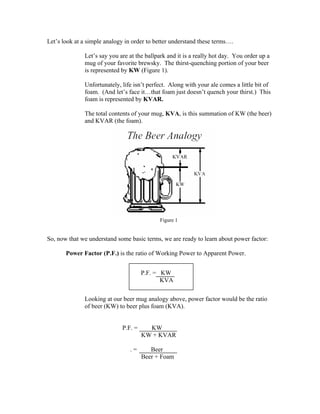
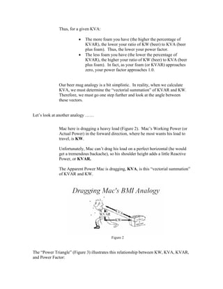
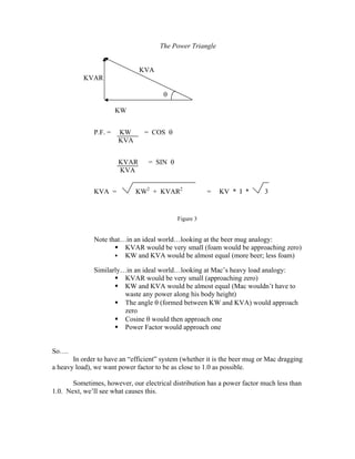
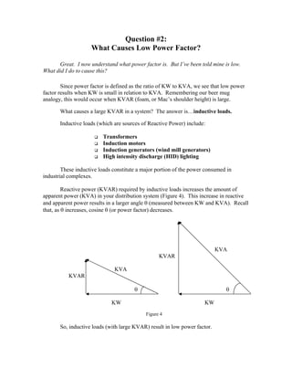
This document provides an overview of power factor, including:
1. It defines power factor as the ratio of working power (KW) to apparent power (KVA), and explains that low power factor is caused by high reactive power (KVAR) from inductive loads like motors and transformers.
2. Improving power factor provides benefits like lower utility bills, increased system capacity, and more efficient operation of motors.
3. Power factor can be improved by adding capacitors, which generate reactive power (KVAR) to offset the reactive power drawn by inductive loads, raising the power factor.
4. An example calculation shows that installing capacitors to improve power factor from 0.65 to 1
The cosine of angle made between the voltage and current is called the power factor.
In AC circuits, there is always the phase deference between the voltage and current, which is calculated in terms of power factor.
If the load is inductive the current lags behind the voltage and the power factor is lagging.
If the load is capacitive the current leads the voltage and the power factor is leading.
The value of power factor can never be more than unity.
Engineering review on AC Power.
Presentation lecture for energy engineering class.
Course: MS in Renewable Energy Engineering, Oregon institute of technology
the ratio of the actual electrical power dissipated by an AC circuit to the product of the r.m.s. values of current and voltage. The difference between the two is caused by reactance in the circuit and represents power that does no useful work.
Power Factor: what it is, how to measure it and how to improve it to reduce u...Pulse Energy
Low power factor is expensive and inefficient. Energy utility companies often charge additional fees to large commercial, institutional, and industrial clients when their power factor drops below 0.95. Understanding power factor and knowing how to measure it and improve it generates significant energy savings for very little cost.
Mike Wrinch, P. Eng. presented an informative 45 minute webinar on understanding, measuring, and improving power factor to reduce energy bills in buildings and facilities. Mike’s presentation included:
* An explanation of power factor and how it affects energy bills and electric systems' distribution capacity
* An overview of the hardware and software needed to measure the power factor in buildings
* Solutions to improve a building’s power factor
We had made a working model on static VAR compensator which is made by power electronic switch and mechanically switched. We had chosen mechanically switched capacitor method to improved receiving end voltage as well as power factor.
In the modern power system the reactive power compensation is one of the main issues, the transmission of active power requires a difference in angular phase between voltages at the sending and receiving points (which is feasible within wide limits), whereas the transmission of reactive power requires a difference in magnitude of these same voltages (which is feasible only within very narrow limits). The reactive power is consumed not only by most of the network elements, but also by most of the consumer loads, so it must be supplied somewhere. If we can't transmit it very easily, then it ought to be generated where it is needed." (Reference Edited by T. J. E. Miller, Forward Page ix).Thus we need to work on the efficient methods by which VAR compensation can be applied easily and we can optimize the modern power system. VAR control technique can provides appropriate placement of compensation devices by which a desirable voltage profile can be achieved and at the same time minimizing the power losses in the system. This report discusses the transmission line requirements for reactive power compensation. In this report thyristor switched capacitor is explained which is a static VAR compensator used for reactive power management in electrical systems.
Seminar Topic For Electrical and Electronics Engineering (EEE)
Capacitor bank and improvement of power factorAhshan Kabir
In these presentation ,we have discussed about power factor, disadvantages of low power factor and how to improve it. Also, capacitor bank and how to install capacitor bank are discussed.
Light as an important architectural element in contemporary architecture..A short dissertation /presentation by..... Atul Pathak ,BIT MESRA..Department of Architecture
Most loads in modern electrical distribution systems are inductive.
Examples include Motors, Transformers, and Induction furnaces. Inductive loads need a magnetic field to operate.
Inductive loads require two kinds of current:
Power-producing current (or working current) is that current which is converted by the equipment into useful work such as creating heat, light, motion ,machine output .
The Unit of measurement of the power produced is the kilowatt (kw).
Micro-controller based Automatic Power Factor Correction System ReportTheory to Practical
This project report represents one of the most effective automatic power factor improvements by using static capacitors which will be controlled by a Microcontroller with very low cost although many existing systems are present which are expensive and difficult to manufacture. In this study, many small rating capacitors are connected in parallel and a reference power factor is set as standard value into the microcontroller IC. Suitable number of static capacitors is automatically connected according to the instruction of the microcontroller to improve the power factor close to unity. Some tricks such as using resistors instead of potential transformer and using one of the most low cost microcontroller IC (ATmega8) which also reduce programming complexity that make it one of the most economical system than any other controlling system.
Improvement of Load Power Factor by Using CapacitorIOSRJEEE
Series and parallel capacitors in the power system effect reactive power to improve power factor and voltage because of increasing the system capacity and reducing losses. Reactive power of series capacitor is the same to the current. There are certain unpleasant aspects in the capacitor series. Generally, the cost to install a series capacitor is higher than parallel capacitor. It is caused by complex protection equipment for series capacitor and designing series capacitors for greater power than parallel capacitor to solve the future cost. Installation of capacitors is important to reduce of a system reactive power. Transmission line would be most economical if it is used to send active power where the need of reactive power can be obtained by distribution system in substation level. This will allow user in optimum transmission line, improve operational performance and reduce energy losses. It requires a system and planning carefully to fulfill the need of system reactive power in the same way with active power planning and it is programmed an additional generator capacity.
Come join the area's leading power quality experts as we demonstrate and replicate common power quality issues, problems and solutions in today's industrial and commercial electrical environments.
INTERIOR LIGHTING DESIGN A STUDENT'S GUIDEno suhaila
This guide on lighting design is intended for students who have no prior knowledge of lighting and also for those who are experienced but would like to bring themselves up to date with developments in lamp and luminaire design, modern design theory, European Standards and the CIBSE code for Interior Lighting 1994.
It develops the basic principles of lighting science but then goes on to provide a modern design perspective for both artificial lighting and day lighting which will be useful to experienced designers.
Interior Lighting: Bringing Rooms To Life teaches the basics of residential interior lighting. The liveaction video demonstrates how the angle, quality, and intensity of light influence how it is perceived and used.
The program explains ambient lighting, task lighting, and accent lighting. It demonstrates different kinds of lamps and lighting fixtures and shows how each contributes to the overall interior design plan.
The video is aimed at students taking introductory courses in interior design or lighting.
Led Lighting (CIBSE Code for Interior Lighting, 1994)no suhaila
There are many standards pertaining to the recommended lighting lux values and the Health & Safety Executive document HSG38 provides guidance on how lighting affects the health and safety of people at work.
A review of the growth of the Israel Genealogy Research Association Database Collection for the last 12 months. Our collection is now passed the 3 million mark and still growing. See which archives have contributed the most. See the different types of records we have, and which years have had records added. You can also see what we have for the future.
This slide is special for master students (MIBS & MIFB) in UUM. Also useful for readers who are interested in the topic of contemporary Islamic banking.
Delivering Micro-Credentials in Technical and Vocational Education and TrainingAG2 Design
Explore how micro-credentials are transforming Technical and Vocational Education and Training (TVET) with this comprehensive slide deck. Discover what micro-credentials are, their importance in TVET, the advantages they offer, and the insights from industry experts. Additionally, learn about the top software applications available for creating and managing micro-credentials. This presentation also includes valuable resources and a discussion on the future of these specialised certifications.
For more detailed information on delivering micro-credentials in TVET, visit this https://tvettrainer.com/delivering-micro-credentials-in-tvet/
Exploiting Artificial Intelligence for Empowering Researchers and Faculty, In...Dr. Vinod Kumar Kanvaria
Exploiting Artificial Intelligence for Empowering Researchers and Faculty,
International FDP on Fundamentals of Research in Social Sciences
at Integral University, Lucknow, 06.06.2024
By Dr. Vinod Kumar Kanvaria
Read| The latest issue of The Challenger is here! We are thrilled to announce that our school paper has qualified for the NATIONAL SCHOOLS PRESS CONFERENCE (NSPC) 2024. Thank you for your unwavering support and trust. Dive into the stories that made us stand out!
2024.06.01 Introducing a competency framework for languag learning materials ...Sandy Millin
http://sandymillin.wordpress.com/iateflwebinar2024
Published classroom materials form the basis of syllabuses, drive teacher professional development, and have a potentially huge influence on learners, teachers and education systems. All teachers also create their own materials, whether a few sentences on a blackboard, a highly-structured fully-realised online course, or anything in between. Despite this, the knowledge and skills needed to create effective language learning materials are rarely part of teacher training, and are mostly learnt by trial and error.
Knowledge and skills frameworks, generally called competency frameworks, for ELT teachers, trainers and managers have existed for a few years now. However, until I created one for my MA dissertation, there wasn’t one drawing together what we need to know and do to be able to effectively produce language learning materials.
This webinar will introduce you to my framework, highlighting the key competencies I identified from my research. It will also show how anybody involved in language teaching (any language, not just English!), teacher training, managing schools or developing language learning materials can benefit from using the framework.
Executive Directors Chat Leveraging AI for Diversity, Equity, and InclusionTechSoup
Let’s explore the intersection of technology and equity in the final session of our DEI series. Discover how AI tools, like ChatGPT, can be used to support and enhance your nonprofit's DEI initiatives. Participants will gain insights into practical AI applications and get tips for leveraging technology to advance their DEI goals.
Safalta Digital marketing institute in Noida, provide complete applications that encompass a huge range of virtual advertising and marketing additives, which includes search engine optimization, virtual communication advertising, pay-per-click on marketing, content material advertising, internet analytics, and greater. These university courses are designed for students who possess a comprehensive understanding of virtual marketing strategies and attributes.Safalta Digital Marketing Institute in Noida is a first choice for young individuals or students who are looking to start their careers in the field of digital advertising. The institute gives specialized courses designed and certification.
for beginners, providing thorough training in areas such as SEO, digital communication marketing, and PPC training in Noida. After finishing the program, students receive the certifications recognised by top different universitie, setting a strong foundation for a successful career in digital marketing.
MATATAG CURRICULUM: ASSESSING THE READINESS OF ELEM. PUBLIC SCHOOL TEACHERS I...NelTorrente
In this research, it concludes that while the readiness of teachers in Caloocan City to implement the MATATAG Curriculum is generally positive, targeted efforts in professional development, resource distribution, support networks, and comprehensive preparation can address the existing gaps and ensure successful curriculum implementation.
The simplified electron and muon model, Oscillating Spacetime: The Foundation...RitikBhardwaj56
Discover the Simplified Electron and Muon Model: A New Wave-Based Approach to Understanding Particles delves into a groundbreaking theory that presents electrons and muons as rotating soliton waves within oscillating spacetime. Geared towards students, researchers, and science buffs, this book breaks down complex ideas into simple explanations. It covers topics such as electron waves, temporal dynamics, and the implications of this model on particle physics. With clear illustrations and easy-to-follow explanations, readers will gain a new outlook on the universe's fundamental nature.
1. Power Factor—
The Basics
OK. I’ve heard a lot about this power factor stuff. What exactly is it?
We hope to give you an easy explanation of what power factor is, and to answer
the following most asked questions:
Question #1: What is Power Factor?
Question #2: What Causes Low Power Factor?
Question #3: Why Should I Improve My Power Factor?
Question #4: How Do I Correct (Improve) My Power Factor?
Question #5: How Long Will It Take My Investment in Power Factor
Correction to Pay for Itself?
Question #6: What is the Next Step?
Question #1:
What is Power Factor?
Super. I’m ready to find out what power factor is.
To understand power factor, we’ll first start with the definition of some basic terms:
KW is Working Power (also called Actual Power or Active Power or Real Power).
It is the power that actually powers the equipment and performs useful
work.
KVAR is Reactive Power.
It is the power that magnetic equipment (transformer, motor and relay)
needs to produce the magnetizing flux.
KVA is Apparent Power.
It is the “vectorial summation” of KVAR and KW.
2. Let’s look at a simple analogy in order to better understand these terms….
Let’s say you are at the ballpark and it is a really hot day. You order up a
mug of your favorite brewsky. The thirst-quenching portion of your beer
is represented by KW (Figure 1).
Unfortunately, life isn’t perfect. Along with your ale comes a little bit of
foam. (And let’s face it…that foam just doesn’t quench your thirst.) This
foam is represented by KVAR.
The total contents of your mug, KVA, is this summation of KW (the beer)
and KVAR (the foam).
Figure 1
So, now that we understand some basic terms, we are ready to learn about power factor:
Power Factor (P.F.) is the ratio of Working Power to Apparent Power.
Looking at our beer mug analogy above, power factor would be the ratio
of beer (KW) to beer plus foam (KVA).
P.F. = KW
KW + KVAR
. = Beer
Beer + Foam
P.F. = KW
KVA
3. Thus, for a given KVA:
• The more foam you have (the higher the percentage of
KVAR), the lower your ratio of KW (beer) to KVA (beer
plus foam). Thus, the lower your power factor.
• The less foam you have (the lower the percentage of
KVAR), the higher your ratio of KW (beer) to KVA (beer
plus foam). In fact, as your foam (or KVAR) approaches
zero, your power factor approaches 1.0.
Our beer mug analogy is a bit simplistic. In reality, when we calculate
KVA, we must determine the “vectorial summation” of KVAR and KW.
Therefore, we must go one step further and look at the angle between
these vectors.
Let’s look at another analogy ……
Mac here is dragging a heavy load (Figure 2). Mac’s Working Power (or
Actual Power) in the forward direction, where he most wants his load to
travel, is KW.
Unfortunately, Mac can’t drag his load on a perfect horizontal (he would
get a tremendous backache), so his shoulder height adds a little Reactive
Power, or KVAR.
The Apparent Power Mac is dragging, KVA, is this “vectorial summation”
of KVAR and KW.
Figure 2
The “Power Triangle” (Figure 3) illustrates this relationship between KW, KVA, KVAR,
and Power Factor:
4. The Power Triangle
KVA
KVAR
θ
KW
P.F. = KW = COS θ
KVA
KVAR = SIN θ
KVA
KVA = KW2
+ KVAR2
= KV * I * 3
Figure 3
Note that…in an ideal world…looking at the beer mug analogy:
KVAR would be very small (foam would be approaching zero)
KW and KVA would be almost equal (more beer; less foam)
Similarly…in an ideal world…looking at Mac’s heavy load analogy:
KVAR would be very small (approaching zero)
KW and KVA would be almost equal (Mac wouldn’t have to
waste any power along his body height)
The angle θ (formed between KW and KVA) would approach
zero
Cosine θ would then approach one
Power Factor would approach one
So….
In order to have an “efficient” system (whether it is the beer mug or Mac dragging
a heavy load), we want power factor to be as close to 1.0 as possible.
Sometimes, however, our electrical distribution has a power factor much less than
1.0. Next, we’ll see what causes this.
5. Question #2:
What Causes Low Power Factor?
Great. I now understand what power factor is. But I’ve been told mine is low.
What did I do to cause this?
Since power factor is defined as the ratio of KW to KVA, we see that low power
factor results when KW is small in relation to KVA. Remembering our beer mug
analogy, this would occur when KVAR (foam, or Mac’s shoulder height) is large.
What causes a large KVAR in a system? The answer is…inductive loads.
Inductive loads (which are sources of Reactive Power) include:
Transformers
Induction motors
Induction generators (wind mill generators)
High intensity discharge (HID) lighting
These inductive loads constitute a major portion of the power consumed in
industrial complexes.
Reactive power (KVAR) required by inductive loads increases the amount of
apparent power (KVA) in your distribution system (Figure 4). This increase in reactive
and apparent power results in a larger angle θ (measured between KW and KVA). Recall
that, as θ increases, cosine θ (or power factor) decreases.
KVA
KVAR
KVA
KVAR
θ θ
KW KW
Figure 4
So, inductive loads (with large KVAR) result in low power factor.
6. Question #3:
Why Should I Improve My Power Factor?
Okay. So I’ve got inductive loads at my facility that are causing my power factor
to be low. Why should I want to improve it?
You want to improve your power factor for several different reasons. Some of the
benefits of improving your power factor include:
1) Lower utility fees by:
a. Reducing peak KW billing demand
Recall that inductive loads, which require reactive power, caused
your low power factor. This increase in required reactive power
(KVAR) causes an increase in required apparent power (KVA),
which is what the utility is supplying.
So, a facility’s low power factor causes the utility to have to
increase its generation and transmission capacity in order to handle
this extra demand.
By raising your power factor, you use less KVAR. This results in
less KW, which equates to a dollar savings from the utility.
b. Eliminating the power factor penalty
Utilities usually charge customers an additional fee when their
power factor is less than 0.95. (In fact, some utilities are not
obligated to deliver electricity to their customer at any time the
customer’s power factor falls below 0.85.) Thus, you can avoid
this additional fee by increasing your power factor.
2) Increased system capacity and reduced system losses in your electrical
system
By adding capacitors (KVAR generators) to the system, the power
factor is improved and the KW capacity of the system is increased.
For example, a 1,000 KVA transformer with an 80% power factor
provides 800 KW (600 KVAR) of power to the main bus.
1000 KVA = (800 KW)2
+ ( ? KVAR)2
KVAR = 600
7. By increasing the power factor to 90%, more KW can be supplied
for the same amount of KVA.
1000 KVA = (900 KW)2
+ ( ? KVAR)2
KVAR = 436
The KW capacity of the system increases to 900 KW and the
utility supplies only 436 KVAR.
Uncorrected power factor causes power system losses in your
distribution system. By improving your power factor, these losses
can be reduced. With the current rise in the cost of energy,
increased facility efficiency is very desirable. And with lower
system losses, you are also able to add additional load to your
system.
3) Increased voltage level in your electrical system and cooler, more efficient
motors
As mentioned above, uncorrected power factor causes power
system losses in your distribution system. As power losses
increase, you may experience voltage drops. Excessive voltage
drops can cause overheating and premature failure of motors and
other inductive equipment.
So, by raising your power factor, you will minimize these voltage
drops along feeder cables and avoid related problems. Your
motors will run cooler and be more efficient, with a slight increase
in capacity and starting torque.
8. Question #4
How Do I Correct (Improve) My Power Factor?
All right. You’ve convinced me. I sure would like to save some money on my
power bill and extend the life of my motors. But how do I go about improving (i.e.,
increasing) my power factor?
We have seen that sources of Reactive Power (inductive loads) decrease power
factor:
Transformers
Induction motors
Induction generators (wind mill generators)
High intensity discharge (HID) lighting
Similarly, consumers of Reactive Power increase power factor:
Capacitors
Synchronous generators (utility and emergency)
Synchronous motors
Thus, it comes as no surprise that one way to increase power factor is to add
capacitors to the system. This--and other ways of increasing power factor--are listed
below:
1) Installing capacitors (KVAR Generators)
Installing capacitors decreases the magnitude of reactive power (KVAR or
foam), thus increasing your power factor.
Here is how it works (Figure 5)…
Reactive power (KVARS), caused by inductive loads,
always acts at a 90-degree angle to working power (KW).
Capacitance
(KVAR)
Working
Power
(KW)
Reactance
(KVAR)
Figure 5
9. Inductance and capacitance react 180 degrees to each other.
Capacitors store KVARS and release energy opposing the
reactive energy caused by the inductor.
The presence of both a capacitor and inductor in the same
circuit results in the continuous alternating transfer of
energy between the two.
Thus, when the circuit is balanced, all the energy released
by the inductor is absorbed by the capacitor.
Following is an example of how a capacitor cancels out the effect of an
inductive load….
2) Minimizing operation of idling or lightly loaded motors.
We already talked about the fact that low power factor is caused by the
presence of induction motors. But, more specifically, low power factor is
caused by running induction motors lightly loaded.
3) Avoiding operation of equipment above its rated voltage.
4) Replacing standard motors as they burn out with energy-efficient motors.
Even with energy-efficient motors, power factor is significantly affected
by variations in load. A motor must be operated near its rated load in
order to realize the benefits of a high power factor design.
10. Question #5
How Long Will It Take my Investment in Power Factor
Correction to Pay for Itself?
Super, I’ve learned that by installing capacitors at my facility, I can improve my power
factor. But buying capacitors costs money. How long will it take for the reduction in my
power bill to pay for the cost of the capacitors?
A calculation can be run to determine when this payoff will be. As an example,
assume that a portion of your facility can be modeled as in Figure 6 below. Your current
power factor is 0.65.
Following are the parameters for your original system:
• 163 KW load
• 730 hours per month
• 480 Volt, 3 phase service
• 5% system losses
• Load PF = 65%
• PSE Rate Schedule:
• Energy Rate = $4.08 per KWH
• Demand Charge = $2.16 per KW
• PF Penalty = $0.15 per KVARH
Figure 6
11. We’ll calculate the total amount the utility charges you every month as follows:
First, we’ll calculate your energy usage:
163 KW X 730 Hours/Month X $4.08/KWH = $4,854.79/Month
Next, we’ll calculate your demand charge:
163 KW X $2.16/KW = $352.08/Month
Finally, we’ll calculate your Power Factor Penalty:
190 KVAR X 730 Hours/Month X $0.15/KVARH = $208/Month
Now, let’s say that you decide to install a capacitor bank (Figure 7). The 190
KVAR from the capacitor cancels out the 190 KVAR from the inductive motor. Your
power factor is now 1.0.
Following are your parameters for your system with capacitors:
• Corrected PF = 1.0
Figure 7
12. You can calculate your loss reduction:
Loss Reduction = 1-(0.652
/ 1.002
) = 0.58
Therefore, your system loss reduction will be as follows:
0.58 X 0.05 (losses) = 0.029 System Loss Reduction
Your total KW load will be reduced as follows:
163 KW X 0.029 = 4.7 KW
Now we can calculate your savings in energy usage:
4.7 KW X 730 Hours/Month X $4.08/KWH = $141.00/Month
Next, we’ll calculate your savings in demand charge:
4.7 KW X $2.16/KW = $10.15/Month
Finally, remember that your Power Factor Penalty is zero.
Let’s calculate how long it will take for this capacitor bank to pay for itself.
• Capacitor Cost = $30.00/KVAR
Your savings per month are as follows:
♦ $141.00 Energy Usage
♦ $ 10.15 Demand Charge
♦ $208.00 PF Penalty Charge
$359.15 Total
Your payback will be at the following time:
$30.00/KVAR X 190 KVAR/$359/Month = 16 Months
Installation of your capacitors will pay for themselves in 16 months.
13. Question #6
What is the next step?
Terrific. I think I should take a look at the power factor at my facility and see
what I can do to improve it. So what do I do next?
PowerStudies.com can assist you in determining the optimum power factor
correction for your facility. We can also help you to correctly locate and provide tips on
installing capacitors in your electrical distribution system.
Feel free to call us, fax us, e-mail us, and continue to check us out on the web.
We would be happy to talk to you about your specific application.
Telephone: (253) 639-8535
Fax: (253) 639-8685
E-mail: fuhr@powerstudies.com
Web: www.powerstudies.com
This article is provided complements of