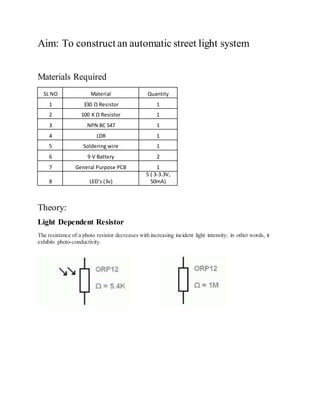
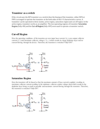
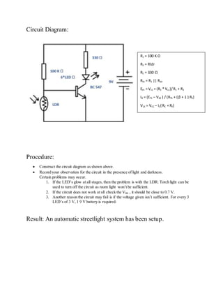
AEC OPEN ENDED REPORT
AUTOMATIC STREET LIGHT SYSTEM
Sankarshan D | PES1201700495 | EEE 3rd SEM
Aim: To construct an automatic street light system
Materials Required
SL NO Material Quantity
1 330 Ω Resistor 1
2 100 K Ω Resistor 1
3 NPN BC 547 1
4 LDR 1
5 Soldering wire 1
6 9 V Battery 2
7 General Purpose PCB 1
8 LED’s (3v)
5 ( 3-3.3V,
50mA)
Theory:
Light Dependent Resistor
The resistance of a photo resistor decreases with increasing incident light intensity; in other words, it
exhibits photo-conductivity.
Transistor as a switch
If the circuituses the BJTtransistor as a switch,then the biasing of the transistor, either NPN or
PNP is arranged to operate the transistor at the both sides of the I-V characteristics curves. A
transistor can be operated in three modes, active region, saturation region and cut-off region. In the
activeregion, transistor works as an amplifier. The twooperating regions of transistor Saturation
Region(fully-ON)andthe Cut-off Region(fully-OFF)wereused to operate a transistor switch.
Cut-off Region
Here the operating conditions of the transistor are zero input base current ( IB ), zero output collector
current ( IC ) and maximum collector voltage ( VCE ) which results in a large depletion layer and no
current flowing through the device. Therefore,the transistor is switched “Fully-OFF”.
Saturation Region
Here the transistor will be biased so that the maximum amount of base current is applied, resulting in
maximum collector current resulting in the minimum collector emitter voltage drop which results in the
depletion layer being as small as possible and maximum current flowing through the transistor. Therefore,
the transistor is switched “Fully-ON”.
Circuit Diagram:
Procedure:
 Construct the circuit diagram as shown above.
 Record your observation for the circuit in the presence of light and darkness.
Certain problems may occur.
1. If the LED’s glow at all stages, then the problem is with the LDR. Torch light can be
used to turn off the circuit as room light won’t be sufficient.
2. If the circuit does not work at all check the VBE , it should be close to 0.7 V.
3. Another reason the circuit may fail is if the voltage given isn’t sufficient. For every 3
LED’s of 3 V, 1 9 V battery is required.
Result: An automatic streetlight system has been setup.
R1 = 100 K Ω
R2 = Rldr
RC = 330 Ω
Rth = R1 || Rldr
Eth = Vr2 = (R2 * Vcc)/R1 + R2
IB = (ETh – VBE ) / (RTh + ( β + 1 ) RE)
VCE = VCC – IC( RC + RE)

Automatic Night Light/ Street Light

  • 1.
    AEC OPEN ENDEDREPORT AUTOMATIC STREET LIGHT SYSTEM Sankarshan D | PES1201700495 | EEE 3rd SEM
  • 2.
    Aim: To constructan automatic street light system Materials Required SL NO Material Quantity 1 330 Ω Resistor 1 2 100 K Ω Resistor 1 3 NPN BC 547 1 4 LDR 1 5 Soldering wire 1 6 9 V Battery 2 7 General Purpose PCB 1 8 LED’s (3v) 5 ( 3-3.3V, 50mA) Theory: Light Dependent Resistor The resistance of a photo resistor decreases with increasing incident light intensity; in other words, it exhibits photo-conductivity.
  • 3.
    Transistor as aswitch If the circuituses the BJTtransistor as a switch,then the biasing of the transistor, either NPN or PNP is arranged to operate the transistor at the both sides of the I-V characteristics curves. A transistor can be operated in three modes, active region, saturation region and cut-off region. In the activeregion, transistor works as an amplifier. The twooperating regions of transistor Saturation Region(fully-ON)andthe Cut-off Region(fully-OFF)wereused to operate a transistor switch. Cut-off Region Here the operating conditions of the transistor are zero input base current ( IB ), zero output collector current ( IC ) and maximum collector voltage ( VCE ) which results in a large depletion layer and no current flowing through the device. Therefore,the transistor is switched “Fully-OFF”. Saturation Region Here the transistor will be biased so that the maximum amount of base current is applied, resulting in maximum collector current resulting in the minimum collector emitter voltage drop which results in the depletion layer being as small as possible and maximum current flowing through the transistor. Therefore, the transistor is switched “Fully-ON”.
  • 4.
    Circuit Diagram: Procedure:  Constructthe circuit diagram as shown above.  Record your observation for the circuit in the presence of light and darkness. Certain problems may occur. 1. If the LED’s glow at all stages, then the problem is with the LDR. Torch light can be used to turn off the circuit as room light won’t be sufficient. 2. If the circuit does not work at all check the VBE , it should be close to 0.7 V. 3. Another reason the circuit may fail is if the voltage given isn’t sufficient. For every 3 LED’s of 3 V, 1 9 V battery is required. Result: An automatic streetlight system has been setup. R1 = 100 K Ω R2 = Rldr RC = 330 Ω Rth = R1 || Rldr Eth = Vr2 = (R2 * Vcc)/R1 + R2 IB = (ETh – VBE ) / (RTh + ( β + 1 ) RE) VCE = VCC – IC( RC + RE)