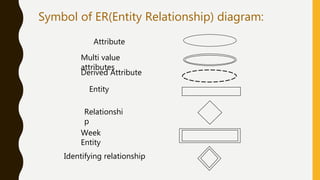
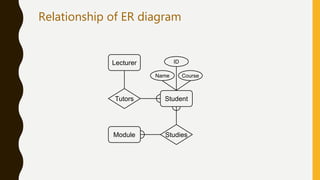
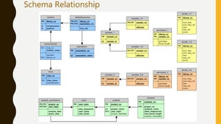
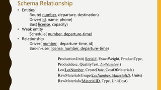
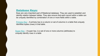
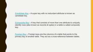
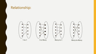
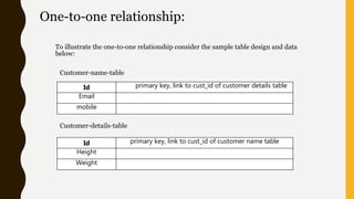
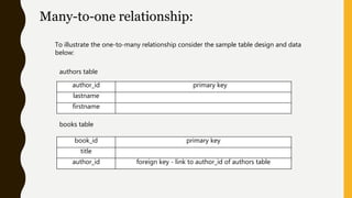
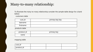
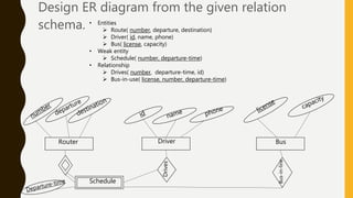
W E L C O M E T O O U R
P R E S E N TAT I O N
Our presentation topic is:
Schema relationship to E-R
diagram.
Symbol of ER(Entity Relationship) diagram:
Attribute
Multi value
attributes
Relationshi
p
Week
Entity
Identifying relationship
Entity
Derived Attribute
Student
Lecturer
Module
Tutors
Studies
ID
CourseName
Relationship of ER diagram
Schema Relationship
Schema Relationship
ProductionUnit( Serial#, ExactWeight, ProductType,
Productdesc, QualityTest, LotNumber )
Lot(LotNumber, CreateDate, CostOfMaterials)
RawMaterialsUsage(LotNumber, MaterialID, Units)
RawMaterials(MaterialID, Type, UnitCost)
• Entities
Route( number, departure, destination)
Driver( id, name, phone)
Bus( license, capacity)
• Weak entity
Schedule( number, departure-time)
• Relationship
Drives( number, departure-time, id)
Bus-in-use( license, number, departure-time)
Database Keys:
Keys are very important part of Relational database. They are used to establish and
identify relation between tables. They also ensure that each record within a table can
be uniquely identified by combination of one or more fields within a table.
Primary Key – A primary key is a column or set of columns in a table that uniquely
identifies tuples (rows) in that table.
Super Key – A super key. is a set of one or more columns (attributes) to
uniquely identify rows in a table
Candidate Key – A super key with no redundant attribute is known as
candidate key.
Composite Key – A key that consists of more than one attribute to uniquely
identify rows (also known as records & tuples) in a table is called composite
key.
Foreign Key – Foreign keys are the columns of a table that points to the
primary key of another table. They act as a cross-reference between tables.
Many-to-Many1-to-1 1-to Many Many-to-1
Relationship:
One-to-one relationship:
To illustrate the one-to-one relationship consider the sample table design and data
below:
Customer-name-table
Id primary key, link to cust_id of customer details table
Email
mobile
Customer-details-table
Id primary key, link to cust_id of customer name table
Height
Weight
To illustrate the one-to-many relationship consider the sample table design and data
below:
authors table
author_id primary key
lastname
firstname
books table
book_id primary key
title
author_id foreign key - link to author_id of authors table
Many-to-one relationship:
To illustrate the many-to-many relationship consider the sample table design for a bank
below:
customers table
cust_id primary key key
lastname
firstname
products table
Many-to-many relationship:
mapping table
product_id primary key
name
cust_id
product_id
Design ER diagram from the given relation
schema. • Entities
 Route( number, departure, destination)
 Driver( id, name, phone)
 Bus( license, capacity)
• Weak entity
 Schedule( number, departure-time)
• Relationship
 Drives( number, departure-time, id)
 Bus-in-use( license, number, departure-time)
Router Driver Bus
Drives
Schedule
Bus-in-line
THANK YOU.

Schema relationship to E-R diagram

  • 1.
    W E LC O M E T O O U R P R E S E N TAT I O N
  • 2.
    Our presentation topicis: Schema relationship to E-R diagram.
  • 3.
    Symbol of ER(EntityRelationship) diagram: Attribute Multi value attributes Relationshi p Week Entity Identifying relationship Entity Derived Attribute
  • 4.
  • 5.
  • 6.
    Schema Relationship ProductionUnit( Serial#,ExactWeight, ProductType, Productdesc, QualityTest, LotNumber ) Lot(LotNumber, CreateDate, CostOfMaterials) RawMaterialsUsage(LotNumber, MaterialID, Units) RawMaterials(MaterialID, Type, UnitCost) • Entities Route( number, departure, destination) Driver( id, name, phone) Bus( license, capacity) • Weak entity Schedule( number, departure-time) • Relationship Drives( number, departure-time, id) Bus-in-use( license, number, departure-time)
  • 7.
    Database Keys: Keys arevery important part of Relational database. They are used to establish and identify relation between tables. They also ensure that each record within a table can be uniquely identified by combination of one or more fields within a table. Primary Key – A primary key is a column or set of columns in a table that uniquely identifies tuples (rows) in that table. Super Key – A super key. is a set of one or more columns (attributes) to uniquely identify rows in a table
  • 8.
    Candidate Key –A super key with no redundant attribute is known as candidate key. Composite Key – A key that consists of more than one attribute to uniquely identify rows (also known as records & tuples) in a table is called composite key. Foreign Key – Foreign keys are the columns of a table that points to the primary key of another table. They act as a cross-reference between tables.
  • 9.
    Many-to-Many1-to-1 1-to ManyMany-to-1 Relationship:
  • 10.
    One-to-one relationship: To illustratethe one-to-one relationship consider the sample table design and data below: Customer-name-table Id primary key, link to cust_id of customer details table Email mobile Customer-details-table Id primary key, link to cust_id of customer name table Height Weight
  • 11.
    To illustrate theone-to-many relationship consider the sample table design and data below: authors table author_id primary key lastname firstname books table book_id primary key title author_id foreign key - link to author_id of authors table Many-to-one relationship:
  • 12.
    To illustrate themany-to-many relationship consider the sample table design for a bank below: customers table cust_id primary key key lastname firstname products table Many-to-many relationship: mapping table product_id primary key name cust_id product_id
  • 13.
    Design ER diagramfrom the given relation schema. • Entities  Route( number, departure, destination)  Driver( id, name, phone)  Bus( license, capacity) • Weak entity  Schedule( number, departure-time) • Relationship  Drives( number, departure-time, id)  Bus-in-use( license, number, departure-time) Router Driver Bus Drives Schedule Bus-in-line
  • 14.