Downloaded 14 times
![IJRET: International Journal of Research in Engineering and Technology eISSN: 2319-1163 | pISSN: 2321-7308
_______________________________________________________________________________________
Volume: 04 Issue: 02 | Feb-2015, Available @ http://www.ijret.org 207
The proposed machine has several devices to do
specified work which will make the robot more
efficient and in safety manner.
If we get sponsor from government or private
organization, we will make the actual robot.
Since the proposed model has only few modifications
and more advantages, it surely improves the rescue
operation with less time.
FUTURE SCOPE
Lower header is under progress and it will be
introduced shortly. This header will be containing
camera, IR LED, mike, oxygen and water supply
tubes and sensors for life saving purpose. For the
purpose of life saving we are going to make the
machine to go inside the bore well.
The cost of rescue machine is high. But comparing to
current military rescue operation, cost is less.
The rescue operation may be declined in case of
foreign bodies over the baby.
As for long distanced operation, there may be
possibilities of breaking of the gas hose or oxygen
hose.
The power transmission through wires along the rope
makes the rope bulkier and it may delay the
operation.
ACKNOWLEDGEMENTS
The first author thankfully acknowledges the support and
co-operation provided by Dharmsinh Desai University,
Nadiad, Gujarat, India and Quantum Age Solution pvt ltd,
Vadodara, Gujarat, India in development of this work.
REFERENCES
[1]. 1Dr. C.N. Sakhale, 2D.M. Mate 3Subhasis Saha, Tomar
Dharmpal, Pranjit Kar, Arindam Sarkar, Rupam Choudhury,
Shahil Kumar , An Approach to Design of Child Saver
Machine for Child Trapped in Borehole , International
Journal of Research in Mechanical Engineering, October-
December, 2013, pp. 26-38.
[2]. K. Saran1, S.Vignesh2, Marlon Jones Louis have
discussed about the project is to design and construct a
“Bore-well rescue robot” (i.e. to rescue a trapped baby from
bore well), International Journal of Research in Aeronautical
and Mechanical Engineering, Boar well rescue robot , pp.
April 2014
[3]. G. Nithin, G. Gowtham, G. Venkatachalam and S.
Narayanan, School of Mechanical Building Sciences, VIT
University, India, Design and Simulation of Bore well
rescue robot– Advanced, ARPN Journal of Engineering and
Applied Sciences, pp. MAY 2014
[4]. B. Bharathi1, B. Suchitha Samuel , M. Tech (Embedded
systems) in Geethanjali College of Engineering and
Technology, Cheeryal (V), Keesara (M), R R Dist, India
have discussed about Design and Construction of Rescue
Robot and Pipeline Inspection Using ZigBee , International
Journal of Scientific Engineering and Research (IJSER),pp.
September 2013.
[5]. Prof. J .P. Ajith Kumar have discussed about Design
Robot for Bore well Rescue Robot for bore well rescue
offers a solution to these kind of
situations,.timeis@ficci.com.
[6]. Sakthivel. T, Sindhulakshmi.K, Bruntha.M, Radhika,
ME Embedded systems and Technologies, Easwari
engineering College Ramapuram, Chennai, Tamilnadu,
SURVEILLANCE PRECISION USING BOREHOLE
NAVIGATION ROBOT, An internatonal journal of
advanced computer technology, Proceeding of 5th National
Conference on VLSI, Embedded, and Communication &
Networks on April 17, 2014
BIOGRAPHIES
Vrunda R shah received her Bachelor of
Engineering with Instrumentation &
control Engineering from government
engineering college, Gandhinagar
Gujarat Technological University,
Ahmedabad, Gujarat, India. Her areas of
interests include Automation Systems,
Virtual Instrumentation and Industrial Process Control,
Biomedical Instrumentation,
E-Mail: er.vrundashah@gmail.com.
Prof. Chirag S. Dalal received his
Bachelor of Engineering with
Instrumentation and Control
Engineering from College L.D
Engineering, Ahmedabad and Master of
Engineering with Instrumentation and
Control Engineering at Indor, India .his
area of interest is power electronics.
E-Mail:chiragsdalal@gmail.com
Rajeev Dubey (M. Tech. – IIT
Kanpur, 1993), Managing Director,
Quantum Age Tech Solutions Pvt. Ltd
Experience: 20 years, Noise and
vibration simulation, measurement and
control.
E-Mail:rajeev@qagetech.com](https://image.slidesharecdn.com/automatemachineforrescueoperationforchild-160829120221/75/Automate-machine-for-rescue-operation-for-child-10-2048.jpg)

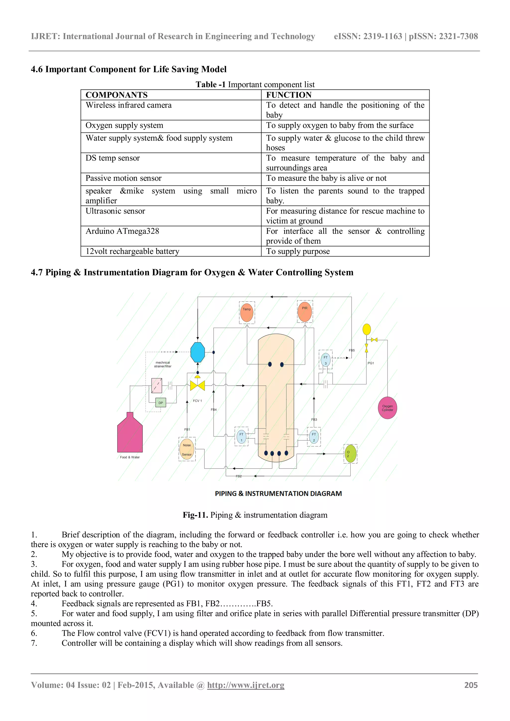
The document describes the design and development of a robotic machine intended to facilitate the rescue of children trapped in bore wells. This machine aims to provide life support by delivering oxygen, food, and water while monitoring the child's condition using sensors and cameras. The proposed solution seeks to reduce the time and risks associated with traditional rescue methods, ultimately saving lives in these tragic situations.