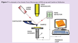
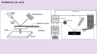
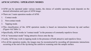
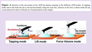
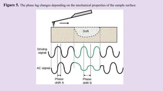
Atomic Force Microscopy
(AFM)
By
Mr. LIKHITH K
(Research Scholar)
Department of Biomedical Engineering
Manipal Institute of Technology
Eshwar Nagar, Manipal, Karnataka-576104
CONTENTS
Introduction
Combinations
• Atomic Force Microscope Infrared (AFM IR)
• Atomic force microscope Optical Microscope (AFM OP)
• Atomic force microscope Total Internal Reflection Fluorescence(AFM TIRF)
• Atomic force microscope Confocal Laser Scanning Microscopy (AFM CLSM)
• Atomic force microscope Fluorescence Lifetime Imaging Microscopy (AFM FLIM)
• Atomic force microscope Reflection Interference Contrast Microscopy (AFM RICM)
Principle and working
Scanning / operation mode
Phase imaging
Applications
Conclusion
Reference
INTRODUCTION
 Atomic force microscope (AFM) is a scanning near-field tool for nanoscale investigation which was invented in 1986.
 Instead of using light or electron beam, AFM uses a sharp tip to ‘‘feel’’ samples. (Fig1)
 As the tip radius of curvature is on the order of nanometers, AFM can detect changes at a spatial resolution up to sub
nanometer level.
Figure 1 A sharp tip to ‘‘feel’’ samples
 Compared to the optical microscope, AFM has a much higher spatial resolution which provides the ability to investigate
ultrafine structure of samples and even map the distribution of single molecules.
 As AFM utilizes direct contact between the tip and the sample, minimum or even no sample preparation is required.
 Moreover, AFM can investigate samples in liquid which provides an opportunity to monitor samples close to their native
surroundings.
Further, AFM provides true 3D images
With optical and electron microscopies, only limited ranges in heights can be ‘‘in-focus’’ at any one time.
Therefore, AFM can provide unique insight into the structure and functional behavior of materials.
AFM is a versatile technique.
Besides scanning the topography of a sample, it can also be used to investigate the mechanical properties of the
sample as well as the interactions between the tip and the sample.
AFM has been successfully applied in widespread branches of science and technology such as nanofabrication,
material science, chemical and drug engineering, biotechnology and microbiology.
As for above mentioned reasons, Atomic force microscope (AFM) is considered a useful tool for the nanoscale
measurement in material-polymer science and engineering.
AFM lacks the robust ability to chemically characterize materials.
COMBINATIONS
Coupling of AFM with infrared and Raman (AFM IR) spectroscopic with nanometer-scale resolution, includes:
1. Tip-Enhanced Raman spectroscopy (TERS)
2. Infrared scattering type Scanning Near-field Optical Microscopy (IR s-SNOM)
3. Thermocouple (nano-TA)
4. Atomic Force Microscopy-Infrared spectroscopy (AFM-IR)
5. Photo-induced Force Microscopy (PiFM)
6. Atomic Force Microscopy Nuclear-Magnetic Resonance (AFM-NMR)
7. Atomic Force Microscopy nuclear- rheometer (Nano-rheology)
were recently developed to overcome these drawbacks.
AFMIR can measure and map local chemical composition below the diffraction limit, as well as nanoscale
topographic, mechanical, and thermal analysis.
This method has been considered one of the most important recent developments in sub-micrometer
spectroscopies and chemical imaging.
The use of this technique has shed light on many assumptions and provided new mechanisms in investigation of
polymer materials.
 Nowadays, AFM-IR has been used to analyze various materials including polymer blends, polymer composites,
multilayer films, polymer thin films, biosciences as well as pharmaceutical blend systems.(Fig 2)
 Additionally, by tuning the source to a fixed wavelength and measuring the deflection as a function of position across
the sample, it can obtain AFM-IR images showing the distribution of chemical species of interest.
 Mechanical and thermal properties of the sample can also be obtained by AFM-IR with suitable devices.
 The AFM-IR can be quickly provided both a nanoscale image and high resolution chemical spectra at selected regions
on the sample and thus helps to identify or quantitative analyses of the complex systems.
Figure 2 Imaging and Mapping Trends For Polymer Materials - Atomic Force Microscopes
AFM-OP (OPTICAL MICROSCOPY)
This combination of the two techniques has made it possible to investigate cellular processes in an unprecedented
way, defying conventional biological practice.
With the aid of light microscopy, precise positioning of the AFM tip into the region of interest of micro sized
objects such as particles or cells is possible, especially after the introduction of technologies that allow the
accurate overlay of optical images and tip lateral displacements.
Using transparent substrates, AFM imaging has been combined with the family of transmitted light optical
microscopies such as
1) Phase and differential interference contrast (P, D-IC)
2) Fluorescence
3) Confocal laser scanning microscopy (CLSM)
4) Total internal reflection fluorescence (TIRF)
5) Fluorescence lifetime imaging microscopy (FLIM)
Recent implementation of AFM with upright microscopes has enabled the extension of the application of the
combined techniques and epifluorescence to non-transparent substrates and hence to a wider range of materials.
Micro and nano interferometric techniques based on transmitted light microscopy such as reflection interference
contrast microscopy (RICM), are particularly useful when combined with AFM.
Indeed, RICM provides complementary information such as absolute tip substrate distances and contact areas,
which the AFM as a stand-alone device cannot produce.
Modification of the AFM setup to be coupled to an inverted or an upright microscope requires the creation of a
obstacle-free optical path to the AFM cantilever and the substrate to be analyzed.
Thus, the configuration of cylindrical piezo scanners mounted upright on tips or on samples is avoided.
In particular, tip-scannable atomic force microscopes are preferable when simultaneous optical and AFM imaging
is required.
In the case of inverted microscopes, a considerable effort in AFM design is needed so as to accommodate optical
condensers of high numerical aperture (0.55) without compromising the quality of optical imaging or instrument
stability.
AFM-TIRF (TOTAL INTERNAL REFLECTION FLUORESCENCE)
TIRF profits from the evanescent wave generated at a surface by a totally reflected light source.
This evanescent wave, which is physically identical to that which excites plasmons on metallic
surfaces, extends a few tens of nano metres along the surface normal.
The wave is capable of exciting fluorophores, which is of particular advantage, since only those in
close proximity to the substrate can be excited.
As a consequence, a fluorescence image of the immediate vicinity of the substrate can be obtained.
An interesting application of the combined AFM-TIRF technique has been applied to live cells.
Cells adhere to affinity substrates by developing so-called focal adhesion points, arrangements of
proteins that act as anchors.
TIRF microscopy (TIRF M) can map the location of these adhesion points while the AFM cantilever
exerts forces on certain cell positions.
In this way, force transmission from the apical membrane to the basal membrane of cells has been
detected from variations in the number and arrangement of focal adhesion points in TIRFM images.
At the molecular level, TIRFM and AFM have been successfully correlated to ascertain the
morphology of myosin self-assembled filaments in a recent study.
AFM-CLSM (CONFOCAL LASER SCANNING MICROSCOPY)
Combining confocal and atomic force microscopy on fluorescently labelled samples has become a
unique tool in imaging molecular complexes on cellular surfaces at high resolution.
The confocal microscope makes use of coherent laser illumination and an optical pinhole system to
extract fluorescence images from different focal planes.
As a result, the sensitivity and image quality is very much improved with respect to conventional
fluorescence microscopy.
Cell organelles can be selectively labelled using standard immune labelling, and co-localized with the
3D topological images provided by the atomic force microscope.
Morphological studies on focal adhesion structures are an example of a successful combination of high
resolution imaging with fluorescence muti labelling to ascertain the localization of interacting
molecules within protein complexes.
AFM-FLIM (FLUORESCENCE LIFETIME IMAGING MICROSCOPY)
This promising combination of techniques has been rather poorly exploited, although it was first reported and
applied in 2002.
The setup shares common features with that of AFM-CLSM and it has mainly been applied to fluorescent nano
spheres, labelled DNA and live bacteria.
Lifetimes of fluorophores attached to molecules or spheres can, however, be altered, which makes the
interpretation of data particularly difficult.
In particular, the presence of the AFM tip—typically Ag or Au metal-coated—can either induce fluorescence
quenching or fluorescence enhancement, which may change lifetimes as well as fluorescence intensity.
The net effect of these two opposing factors is not possible to predict to date.
AFM-RICM (REFLECTION INTERFERENCE CONTRAST MICROSCOPY)
Combining these two techniques is especially advantageous when studying surface interactions and
mechanics.
AFM as a dynamometer detects forces exerted between two interacting surfaces as they are being
approached or separated; the force is quantified through the cantilever deflection, which behaves as a
linear spring.
RICM as an interferometer is capable of detecting the distance between these two surfaces with a
precision on the order of 1–3 nm.
To do that, light is shone on the region between the AFM probe, usually a glass bead, and the substrate.
The light is reflected at both interfaces, i.e. that between the substrate and the surrounding medium and
that between the medium and the probe.
Constructive and destructive interference between the two reflected rays occurs as the tip–substrate
separation varies.
The interference pattern is thus a function of the tip–substrate distance, and also of the bead contour,
the wavelength of the incident light and the optical properties of the medium.
Using this combined approach, protein– ligand interactions and microcapsule and droplet deformability
have been verified.
THE PRINCIPLE AND WORKING OF AFM
Atomic force microscopy is based on determining the interaction between the surface of the analyzed
sample and the probe of the microscope, which is fixed at the end of an elastic cantilever console.
The bending of the console occurs due to the forces acting on the probe from the sample side.
The force of interaction of the probe with the surface is controlled by fixing the bending level.
The radiation of the semiconductor laser is focused on the elastic console of the probe sensor.
The reflected radiation is fixed using a photosensitive element, a photodiode with four sections, which
makes it possible to determine the direction and degree of displacement of the probe sensor console.
The main characteristics recorded by the optical system are the degree of torsion deformation under the
action of tangential components of the interaction forces of the probe with the surface.
And the degree of bending deformation of the console under the action of the normal component of the
attraction or repulsion forces.
Before starting the analysis the optical system of the microscope should be adjusted so that the reflected radiation
falls into the center of the photodetector.
The photocurrents from all sections of the photodiode will have the same value.
Due to the deformation of the bending of the console under the action of interaction forces the reflected beam is
deflected from the central position.
The change in the photocurrent in each section is the result of this shift.
The degree and direction of displacement of the cantilever console is parameterized by a change in the
photocurrent, which is called the difference current.
The photocurrent received from 4 sections of the photodiode allows creating a voltage in the feedback unit, which
is stored as a surface relief.
The distance between the probe of the microscope and the surface of the analyzed sample is maintained at an
unchanged level by means of a tubular piezo motor.
The voltage that is applied to the tubular piezo motor is the voltage in the feedback circuit.
Atomic force microscopy (AFM) is a tool for the study of phenomena at the nanoscale, which includes
quantitative single molecule studies.
AFM is an unparalleled tool for observing temporal changes introduction in cell and polymer
morphology.
The development of devices that operate at elevated temperature has enabled the direct observation of
polymer crystallization and melting, as well as structural changes occurring during the annealing of
thin, metastable lamellar crystals.
AFM is commonly used in the field of polymer crystallization.
Generally, the effect of the AFM tip throughout the scan should be diminished in order to truly reflect
the crystal morphology and crystallization mechanism.
It is a high-resolution technology, regularly with the resolution of sub 10 nm features and due to
enable the fundamental length scale of the polymer lamellar crystal, its thickness, to be perceived.
AFM does not require sample staining or metal coating, so it is straightforward to prepare the
specimen.
In many cases, it is also non-destructive.
It makes images to be captured whereas a process such as melting or crystal growth occurs, providing
lamellar or sub-lamellar resolution time-resolved data.
It is a final feature that provides many of AFM's most interesting opportunities to study polymer
crystallization, as it is now possible to observe crystal melting, crystal growth and lamellar-scale
reorganizations within crystals, seeing how structure evolve and local conditions affect kinetics.
A graphic of an AFM set-up is displayed in Figure 3.
The main element is sensor, a pyramidal tip attached to a 100-400 μm long cantilever, which is in contact with
the sample surface.
Cantilever and tip are often made of silicon or silicon nitride, because these materials allow relatively low-cost
mass production using semi-conductor technology.
The geometry of the apex of the tip is representing one of the key parameters determining the resolution.
With a tip that ends in a single atom, the highest resolutions can be reached.
The cantilever is a system comparable to a contact profilometry, with the 3D displacement of the AFM tip
relative to the pattern being received with the aid of piezoelectric crystals.
This set-up allows for placing of the AFM tip with an accuracy of approximately 1 nm in x-, y- and z-direction.
When the AFM tip is engaging a surface, the cantilever is bending due to repulsive forces between tip and
sample.
This deflection, proportional to the pressure either being applied to the specimen, is used to represent a
topography of the surface directly or as an input for the feedback loop controlling the AFM's z-position.
There are several different techniques for quantifying this deflection.
However, the most common use of an optical sensor is a laser beam that is reflected from the cantilever backside
to a position-sensitive light detector.
Because the laser place on the detector varies in accordance with the degree of bending of the cantilever of the
AFM, the latter can be measured accordingly.
Figure 3 A schematic of an Atomic Force Microscopy (AFM) set-up and Cantilever Deflection
WORKING OF AFM
AFM SCANNING / OPERATION MODES
AFM can be operated under various modes, the choice of suitable operating mode depends on the
desired information and types of AFM image.
There are 3 main operation modes of AFM:
1. Contact mode
2. Non-contact mode
3. Tapping mode.
This classification of the AFM operation modes is based on interactions between tip and surface
(Figure 4 & Table 1).
Specifically, AFM works in “contact mode” in the presence of constantly repulsive forces
Or in “noncontact mode” being attractive forces onto the tip.
Lastly, AFM may work in tapping mode in the presence of both attractive and repulsive force.
For all the operation modes, the images may be reconstructed by recording all interatomic interactions
occurring at the end of the tip during the cantilever scanning onto the sample surface.
Figure. 4 Schemes of the movement of the AFM tip during scanning in the different AFM modes. In tapping
mode and in lift mode the tip is moved horizontally along the scan line, whereas in the force volume mode the tip
is moved pixel by pixel vertically at a fixed position on the sample.
Table 1. Summary of AFM modes of operation (scanning)
1.Contact mode (CM)
AFM Contact is mostly named a static mode.
The contact operational mode is the most suitable for flat and rigid surfaces such as crystal, hard polymers and
tissue, enabling the highest resolution level.
In this mode, it is possible to capture image artifacts associated with a not-flat surface or to a mechanical drift
derived from the scanner motion.
These artifacts can prevail the topography image over the real morphological features.
To intercept these artifacts and to measure how well the desired deflection set point is maintained constant by the
feedback system, the error mode can be used.
2. Non contact mode (NC)
In non-contact mode, the oscillating probe is generally influenced by the close surface, so producing a frequency
shift in the resonant frequency, due to Van der Waals attractive forces.
Hence, the signals recorded in non-contact mode are related to the variation between cantilever resonance
frequency and free oscillation of the system, giving a preliminary estimation of atomic tip-sample interaction
forces intensities.
Tapping and noncontact are called dynamic modes, as the cantilever is oscillated in tapping and noncontact
modes.
Typically, this is done by adding an extra piezoelectric element that oscillates up and down at
somewhere between 5-400 kHz to the cantilever holder.
Noncontact AFM, unlike the other AFM techniques can obtain true atomic resolution images.
3. Tapping mode (TM)
Tapping mode would then be called Amplitude Modulation AFM (AM-AFM).
In the case of tapping or intermittent contact AFM (IC-AFM), probe excitation externally occurs, and
the amplitude and cantilever phase may be monitored in the proximity of the resonance frequency.
With respect to the other operation modes, tapping mode has been employed successfully for the
topographic characterization of cell-loaded surfaces, due to the application of lower forces and high-
resolution imaging.
The main difference between tapping mode and non contact mode is
In tapping mode; the tip of the probe actually touches the sample and moves completely away from the sample
in each oscillation cycle.
In NC-AFM, the cantilever stays close to the sample all the times and has a much smaller oscillation amplitude.
NC-AFM is more sensitive to small oscillations of the cantilever, so may be operated in close contact (almost
touching).
NC AFM, unlike the other AFM techniques can obtain true atomic resolution images.
Amplitude Modulation (AM)-AFM is typically used for tapping mode, where the tip actually taps the sample
during each oscillation.
This is often the most stable mode to use in air, and so is currently more commonly used than either noncontact
or contact modes for most applications.
PHASE IMAGING
The contrast of an atomic force micrograph generally depends on the mechanical properties of the surface and
the probe, for instance, the adhesiveness and elasticity.
To produce a sharp image of the surface topography, the sample material has to be relatively rigid compared to
the probe.
As the material becomes softer, the image obtained will become more influenced by the elastic properties of the
surface.
In extreme cases, the tip-surface interaction can cause damage or displacement of the sample.
Phase imaging, a method closely associated with IC-AFM, enables surface properties to be observed beyond
pure topography.
Once scanning in IC-AFM, the damping of the oscillation outcomes in a loss of oscillation energy occurred in
the cantilever due to energy transfer to the sample.
This results in a phase change as well as the lower amplitude of the cantilever oscillation.
Since this phase change is a feature of the sample material's energy absorbency, it is idiosyncratic for rigid or
soft materials or, more generally, low and high-energy absorbency materials (Figure 5)
Figure 5. The phase lag changes depending on the mechanical properties of the sample surface:
It results in a phase shift of the cantilever oscillation as well as the lower amplitude.
As this phase shift is a function of energy absorbency of the sample material, it is idiosyncratic for stiff or soft
materials, or more precisely, materials with high and low energy absorbency.
This allows analyzing the distribution of different materials or phases within the sample, for example, phase
separation within lipids or drug distribution within nanoparticles.
APPLICATIONS
This type of microscopy has been used in various disciplines in natural science such as solid-state
physics, semiconductor studies, molecular engineering, polymer chemistry, surface chemistry,
molecular biology, biotechnology, biomedical engineering, chemical engineering, cell biology,
medicine, and physics.
Some of these applications include:
Identifying atoms from samples.
Evaluating force interactions between atoms.
Studying the physical changing properties of atoms.
Studying the structural and mechanical properties of protein complexes and assembly, such as
microtubules.
Studding the surface topography of polymer and nanocomposites.
Used to differentiate cancer cells and normal cells.
Evaluating and differentiating neighboring cells and their shape and cell wall rigidity.
CONCLUSIONS
AFM has been proved to be a powerful tool for morphology and rheology studies in various felids of science and
technology, providing unique insights into structures and functional behaviors on the nanoscale.
It is widely applied in fundamental researches of basic chemistry as well as complicated biological systems.
Structures of molecules and their aggregates, local rheological properties, and functional mechanisms are
revealed.
With the help of other macroscale analysis techniques (IR), researchers could correlate the nanoscale structures
observed with AFM to the bulk properties of the samples.
AFM will continuously play an important role in nano and micro research, and the above mentioned analytical
techniques will be applied in more fields.
With improvements in the instrument, researchers will be able to investigate a wider range of samples closer to
their native status.
Combinations with other complementary analysis techniques may provide more comprehensive information of
the research object.
AFM will always provide opportunities for researchers to discover a vivid world on the nanoscale.
REFERENCE
Phuong Nguyen-Tri etal, Recent Applications of Advanced Atomic Force Microscopy in Polymer Science: A
Review, Polymers. May 2020
Shaoyang Liu etal, A Review of the Application of Atomic Force Microscopy (AFM) in Food Science and
Technology, Advances in Food and Nutrition Research. December 2011
 Susana etal, The new future of scanning probe microscopy: Combining atomic force microscopy with other
surface-sensitive techniques, optical microscopy and fluorescence techniques. September 2009
THANK YOU

Atomic force microscopy (AFM) Likhith K

  • 1.
    Atomic Force Microscopy (AFM) By Mr.LIKHITH K (Research Scholar) Department of Biomedical Engineering Manipal Institute of Technology Eshwar Nagar, Manipal, Karnataka-576104
  • 2.
    CONTENTS Introduction Combinations • Atomic ForceMicroscope Infrared (AFM IR) • Atomic force microscope Optical Microscope (AFM OP) • Atomic force microscope Total Internal Reflection Fluorescence(AFM TIRF) • Atomic force microscope Confocal Laser Scanning Microscopy (AFM CLSM) • Atomic force microscope Fluorescence Lifetime Imaging Microscopy (AFM FLIM) • Atomic force microscope Reflection Interference Contrast Microscopy (AFM RICM) Principle and working Scanning / operation mode Phase imaging Applications Conclusion Reference
  • 3.
    INTRODUCTION  Atomic forcemicroscope (AFM) is a scanning near-field tool for nanoscale investigation which was invented in 1986.  Instead of using light or electron beam, AFM uses a sharp tip to ‘‘feel’’ samples. (Fig1)  As the tip radius of curvature is on the order of nanometers, AFM can detect changes at a spatial resolution up to sub nanometer level. Figure 1 A sharp tip to ‘‘feel’’ samples  Compared to the optical microscope, AFM has a much higher spatial resolution which provides the ability to investigate ultrafine structure of samples and even map the distribution of single molecules.  As AFM utilizes direct contact between the tip and the sample, minimum or even no sample preparation is required.  Moreover, AFM can investigate samples in liquid which provides an opportunity to monitor samples close to their native surroundings.
  • 4.
    Further, AFM providestrue 3D images With optical and electron microscopies, only limited ranges in heights can be ‘‘in-focus’’ at any one time. Therefore, AFM can provide unique insight into the structure and functional behavior of materials. AFM is a versatile technique. Besides scanning the topography of a sample, it can also be used to investigate the mechanical properties of the sample as well as the interactions between the tip and the sample. AFM has been successfully applied in widespread branches of science and technology such as nanofabrication, material science, chemical and drug engineering, biotechnology and microbiology. As for above mentioned reasons, Atomic force microscope (AFM) is considered a useful tool for the nanoscale measurement in material-polymer science and engineering. AFM lacks the robust ability to chemically characterize materials.
  • 5.
    COMBINATIONS Coupling of AFMwith infrared and Raman (AFM IR) spectroscopic with nanometer-scale resolution, includes: 1. Tip-Enhanced Raman spectroscopy (TERS) 2. Infrared scattering type Scanning Near-field Optical Microscopy (IR s-SNOM) 3. Thermocouple (nano-TA) 4. Atomic Force Microscopy-Infrared spectroscopy (AFM-IR) 5. Photo-induced Force Microscopy (PiFM) 6. Atomic Force Microscopy Nuclear-Magnetic Resonance (AFM-NMR) 7. Atomic Force Microscopy nuclear- rheometer (Nano-rheology) were recently developed to overcome these drawbacks. AFMIR can measure and map local chemical composition below the diffraction limit, as well as nanoscale topographic, mechanical, and thermal analysis. This method has been considered one of the most important recent developments in sub-micrometer spectroscopies and chemical imaging. The use of this technique has shed light on many assumptions and provided new mechanisms in investigation of polymer materials.
  • 6.
     Nowadays, AFM-IRhas been used to analyze various materials including polymer blends, polymer composites, multilayer films, polymer thin films, biosciences as well as pharmaceutical blend systems.(Fig 2)  Additionally, by tuning the source to a fixed wavelength and measuring the deflection as a function of position across the sample, it can obtain AFM-IR images showing the distribution of chemical species of interest.  Mechanical and thermal properties of the sample can also be obtained by AFM-IR with suitable devices.  The AFM-IR can be quickly provided both a nanoscale image and high resolution chemical spectra at selected regions on the sample and thus helps to identify or quantitative analyses of the complex systems. Figure 2 Imaging and Mapping Trends For Polymer Materials - Atomic Force Microscopes
  • 7.
    AFM-OP (OPTICAL MICROSCOPY) Thiscombination of the two techniques has made it possible to investigate cellular processes in an unprecedented way, defying conventional biological practice. With the aid of light microscopy, precise positioning of the AFM tip into the region of interest of micro sized objects such as particles or cells is possible, especially after the introduction of technologies that allow the accurate overlay of optical images and tip lateral displacements. Using transparent substrates, AFM imaging has been combined with the family of transmitted light optical microscopies such as 1) Phase and differential interference contrast (P, D-IC) 2) Fluorescence 3) Confocal laser scanning microscopy (CLSM) 4) Total internal reflection fluorescence (TIRF) 5) Fluorescence lifetime imaging microscopy (FLIM) Recent implementation of AFM with upright microscopes has enabled the extension of the application of the combined techniques and epifluorescence to non-transparent substrates and hence to a wider range of materials.
  • 8.
    Micro and nanointerferometric techniques based on transmitted light microscopy such as reflection interference contrast microscopy (RICM), are particularly useful when combined with AFM. Indeed, RICM provides complementary information such as absolute tip substrate distances and contact areas, which the AFM as a stand-alone device cannot produce. Modification of the AFM setup to be coupled to an inverted or an upright microscope requires the creation of a obstacle-free optical path to the AFM cantilever and the substrate to be analyzed. Thus, the configuration of cylindrical piezo scanners mounted upright on tips or on samples is avoided. In particular, tip-scannable atomic force microscopes are preferable when simultaneous optical and AFM imaging is required. In the case of inverted microscopes, a considerable effort in AFM design is needed so as to accommodate optical condensers of high numerical aperture (0.55) without compromising the quality of optical imaging or instrument stability.
  • 9.
    AFM-TIRF (TOTAL INTERNALREFLECTION FLUORESCENCE) TIRF profits from the evanescent wave generated at a surface by a totally reflected light source. This evanescent wave, which is physically identical to that which excites plasmons on metallic surfaces, extends a few tens of nano metres along the surface normal. The wave is capable of exciting fluorophores, which is of particular advantage, since only those in close proximity to the substrate can be excited. As a consequence, a fluorescence image of the immediate vicinity of the substrate can be obtained. An interesting application of the combined AFM-TIRF technique has been applied to live cells. Cells adhere to affinity substrates by developing so-called focal adhesion points, arrangements of proteins that act as anchors. TIRF microscopy (TIRF M) can map the location of these adhesion points while the AFM cantilever exerts forces on certain cell positions. In this way, force transmission from the apical membrane to the basal membrane of cells has been detected from variations in the number and arrangement of focal adhesion points in TIRFM images. At the molecular level, TIRFM and AFM have been successfully correlated to ascertain the morphology of myosin self-assembled filaments in a recent study.
  • 10.
    AFM-CLSM (CONFOCAL LASERSCANNING MICROSCOPY) Combining confocal and atomic force microscopy on fluorescently labelled samples has become a unique tool in imaging molecular complexes on cellular surfaces at high resolution. The confocal microscope makes use of coherent laser illumination and an optical pinhole system to extract fluorescence images from different focal planes. As a result, the sensitivity and image quality is very much improved with respect to conventional fluorescence microscopy. Cell organelles can be selectively labelled using standard immune labelling, and co-localized with the 3D topological images provided by the atomic force microscope. Morphological studies on focal adhesion structures are an example of a successful combination of high resolution imaging with fluorescence muti labelling to ascertain the localization of interacting molecules within protein complexes.
  • 11.
    AFM-FLIM (FLUORESCENCE LIFETIMEIMAGING MICROSCOPY) This promising combination of techniques has been rather poorly exploited, although it was first reported and applied in 2002. The setup shares common features with that of AFM-CLSM and it has mainly been applied to fluorescent nano spheres, labelled DNA and live bacteria. Lifetimes of fluorophores attached to molecules or spheres can, however, be altered, which makes the interpretation of data particularly difficult. In particular, the presence of the AFM tip—typically Ag or Au metal-coated—can either induce fluorescence quenching or fluorescence enhancement, which may change lifetimes as well as fluorescence intensity. The net effect of these two opposing factors is not possible to predict to date.
  • 12.
    AFM-RICM (REFLECTION INTERFERENCECONTRAST MICROSCOPY) Combining these two techniques is especially advantageous when studying surface interactions and mechanics. AFM as a dynamometer detects forces exerted between two interacting surfaces as they are being approached or separated; the force is quantified through the cantilever deflection, which behaves as a linear spring. RICM as an interferometer is capable of detecting the distance between these two surfaces with a precision on the order of 1–3 nm. To do that, light is shone on the region between the AFM probe, usually a glass bead, and the substrate. The light is reflected at both interfaces, i.e. that between the substrate and the surrounding medium and that between the medium and the probe. Constructive and destructive interference between the two reflected rays occurs as the tip–substrate separation varies. The interference pattern is thus a function of the tip–substrate distance, and also of the bead contour, the wavelength of the incident light and the optical properties of the medium. Using this combined approach, protein– ligand interactions and microcapsule and droplet deformability have been verified.
  • 13.
    THE PRINCIPLE ANDWORKING OF AFM Atomic force microscopy is based on determining the interaction between the surface of the analyzed sample and the probe of the microscope, which is fixed at the end of an elastic cantilever console. The bending of the console occurs due to the forces acting on the probe from the sample side. The force of interaction of the probe with the surface is controlled by fixing the bending level. The radiation of the semiconductor laser is focused on the elastic console of the probe sensor. The reflected radiation is fixed using a photosensitive element, a photodiode with four sections, which makes it possible to determine the direction and degree of displacement of the probe sensor console. The main characteristics recorded by the optical system are the degree of torsion deformation under the action of tangential components of the interaction forces of the probe with the surface. And the degree of bending deformation of the console under the action of the normal component of the attraction or repulsion forces.
  • 14.
    Before starting theanalysis the optical system of the microscope should be adjusted so that the reflected radiation falls into the center of the photodetector. The photocurrents from all sections of the photodiode will have the same value. Due to the deformation of the bending of the console under the action of interaction forces the reflected beam is deflected from the central position. The change in the photocurrent in each section is the result of this shift. The degree and direction of displacement of the cantilever console is parameterized by a change in the photocurrent, which is called the difference current. The photocurrent received from 4 sections of the photodiode allows creating a voltage in the feedback unit, which is stored as a surface relief. The distance between the probe of the microscope and the surface of the analyzed sample is maintained at an unchanged level by means of a tubular piezo motor. The voltage that is applied to the tubular piezo motor is the voltage in the feedback circuit.
  • 15.
    Atomic force microscopy(AFM) is a tool for the study of phenomena at the nanoscale, which includes quantitative single molecule studies. AFM is an unparalleled tool for observing temporal changes introduction in cell and polymer morphology. The development of devices that operate at elevated temperature has enabled the direct observation of polymer crystallization and melting, as well as structural changes occurring during the annealing of thin, metastable lamellar crystals. AFM is commonly used in the field of polymer crystallization. Generally, the effect of the AFM tip throughout the scan should be diminished in order to truly reflect the crystal morphology and crystallization mechanism. It is a high-resolution technology, regularly with the resolution of sub 10 nm features and due to enable the fundamental length scale of the polymer lamellar crystal, its thickness, to be perceived. AFM does not require sample staining or metal coating, so it is straightforward to prepare the specimen. In many cases, it is also non-destructive. It makes images to be captured whereas a process such as melting or crystal growth occurs, providing lamellar or sub-lamellar resolution time-resolved data. It is a final feature that provides many of AFM's most interesting opportunities to study polymer crystallization, as it is now possible to observe crystal melting, crystal growth and lamellar-scale reorganizations within crystals, seeing how structure evolve and local conditions affect kinetics.
  • 16.
    A graphic ofan AFM set-up is displayed in Figure 3. The main element is sensor, a pyramidal tip attached to a 100-400 μm long cantilever, which is in contact with the sample surface. Cantilever and tip are often made of silicon or silicon nitride, because these materials allow relatively low-cost mass production using semi-conductor technology. The geometry of the apex of the tip is representing one of the key parameters determining the resolution. With a tip that ends in a single atom, the highest resolutions can be reached. The cantilever is a system comparable to a contact profilometry, with the 3D displacement of the AFM tip relative to the pattern being received with the aid of piezoelectric crystals. This set-up allows for placing of the AFM tip with an accuracy of approximately 1 nm in x-, y- and z-direction. When the AFM tip is engaging a surface, the cantilever is bending due to repulsive forces between tip and sample. This deflection, proportional to the pressure either being applied to the specimen, is used to represent a topography of the surface directly or as an input for the feedback loop controlling the AFM's z-position. There are several different techniques for quantifying this deflection. However, the most common use of an optical sensor is a laser beam that is reflected from the cantilever backside to a position-sensitive light detector. Because the laser place on the detector varies in accordance with the degree of bending of the cantilever of the AFM, the latter can be measured accordingly.
  • 17.
    Figure 3 Aschematic of an Atomic Force Microscopy (AFM) set-up and Cantilever Deflection
  • 18.
  • 19.
    AFM SCANNING /OPERATION MODES AFM can be operated under various modes, the choice of suitable operating mode depends on the desired information and types of AFM image. There are 3 main operation modes of AFM: 1. Contact mode 2. Non-contact mode 3. Tapping mode. This classification of the AFM operation modes is based on interactions between tip and surface (Figure 4 & Table 1). Specifically, AFM works in “contact mode” in the presence of constantly repulsive forces Or in “noncontact mode” being attractive forces onto the tip. Lastly, AFM may work in tapping mode in the presence of both attractive and repulsive force. For all the operation modes, the images may be reconstructed by recording all interatomic interactions occurring at the end of the tip during the cantilever scanning onto the sample surface.
  • 20.
    Figure. 4 Schemesof the movement of the AFM tip during scanning in the different AFM modes. In tapping mode and in lift mode the tip is moved horizontally along the scan line, whereas in the force volume mode the tip is moved pixel by pixel vertically at a fixed position on the sample.
  • 21.
    Table 1. Summaryof AFM modes of operation (scanning)
  • 22.
    1.Contact mode (CM) AFMContact is mostly named a static mode. The contact operational mode is the most suitable for flat and rigid surfaces such as crystal, hard polymers and tissue, enabling the highest resolution level. In this mode, it is possible to capture image artifacts associated with a not-flat surface or to a mechanical drift derived from the scanner motion. These artifacts can prevail the topography image over the real morphological features. To intercept these artifacts and to measure how well the desired deflection set point is maintained constant by the feedback system, the error mode can be used. 2. Non contact mode (NC) In non-contact mode, the oscillating probe is generally influenced by the close surface, so producing a frequency shift in the resonant frequency, due to Van der Waals attractive forces. Hence, the signals recorded in non-contact mode are related to the variation between cantilever resonance frequency and free oscillation of the system, giving a preliminary estimation of atomic tip-sample interaction forces intensities. Tapping and noncontact are called dynamic modes, as the cantilever is oscillated in tapping and noncontact modes.
  • 23.
    Typically, this isdone by adding an extra piezoelectric element that oscillates up and down at somewhere between 5-400 kHz to the cantilever holder. Noncontact AFM, unlike the other AFM techniques can obtain true atomic resolution images. 3. Tapping mode (TM) Tapping mode would then be called Amplitude Modulation AFM (AM-AFM). In the case of tapping or intermittent contact AFM (IC-AFM), probe excitation externally occurs, and the amplitude and cantilever phase may be monitored in the proximity of the resonance frequency. With respect to the other operation modes, tapping mode has been employed successfully for the topographic characterization of cell-loaded surfaces, due to the application of lower forces and high- resolution imaging.
  • 25.
    The main differencebetween tapping mode and non contact mode is In tapping mode; the tip of the probe actually touches the sample and moves completely away from the sample in each oscillation cycle. In NC-AFM, the cantilever stays close to the sample all the times and has a much smaller oscillation amplitude. NC-AFM is more sensitive to small oscillations of the cantilever, so may be operated in close contact (almost touching). NC AFM, unlike the other AFM techniques can obtain true atomic resolution images. Amplitude Modulation (AM)-AFM is typically used for tapping mode, where the tip actually taps the sample during each oscillation. This is often the most stable mode to use in air, and so is currently more commonly used than either noncontact or contact modes for most applications.
  • 26.
    PHASE IMAGING The contrastof an atomic force micrograph generally depends on the mechanical properties of the surface and the probe, for instance, the adhesiveness and elasticity. To produce a sharp image of the surface topography, the sample material has to be relatively rigid compared to the probe. As the material becomes softer, the image obtained will become more influenced by the elastic properties of the surface. In extreme cases, the tip-surface interaction can cause damage or displacement of the sample. Phase imaging, a method closely associated with IC-AFM, enables surface properties to be observed beyond pure topography. Once scanning in IC-AFM, the damping of the oscillation outcomes in a loss of oscillation energy occurred in the cantilever due to energy transfer to the sample. This results in a phase change as well as the lower amplitude of the cantilever oscillation. Since this phase change is a feature of the sample material's energy absorbency, it is idiosyncratic for rigid or soft materials or, more generally, low and high-energy absorbency materials (Figure 5)
  • 27.
    Figure 5. Thephase lag changes depending on the mechanical properties of the sample surface:
  • 28.
    It results ina phase shift of the cantilever oscillation as well as the lower amplitude. As this phase shift is a function of energy absorbency of the sample material, it is idiosyncratic for stiff or soft materials, or more precisely, materials with high and low energy absorbency. This allows analyzing the distribution of different materials or phases within the sample, for example, phase separation within lipids or drug distribution within nanoparticles.
  • 29.
    APPLICATIONS This type ofmicroscopy has been used in various disciplines in natural science such as solid-state physics, semiconductor studies, molecular engineering, polymer chemistry, surface chemistry, molecular biology, biotechnology, biomedical engineering, chemical engineering, cell biology, medicine, and physics. Some of these applications include: Identifying atoms from samples. Evaluating force interactions between atoms. Studying the physical changing properties of atoms. Studying the structural and mechanical properties of protein complexes and assembly, such as microtubules. Studding the surface topography of polymer and nanocomposites. Used to differentiate cancer cells and normal cells. Evaluating and differentiating neighboring cells and their shape and cell wall rigidity.
  • 30.
    CONCLUSIONS AFM has beenproved to be a powerful tool for morphology and rheology studies in various felids of science and technology, providing unique insights into structures and functional behaviors on the nanoscale. It is widely applied in fundamental researches of basic chemistry as well as complicated biological systems. Structures of molecules and their aggregates, local rheological properties, and functional mechanisms are revealed. With the help of other macroscale analysis techniques (IR), researchers could correlate the nanoscale structures observed with AFM to the bulk properties of the samples. AFM will continuously play an important role in nano and micro research, and the above mentioned analytical techniques will be applied in more fields. With improvements in the instrument, researchers will be able to investigate a wider range of samples closer to their native status. Combinations with other complementary analysis techniques may provide more comprehensive information of the research object. AFM will always provide opportunities for researchers to discover a vivid world on the nanoscale.
  • 31.
    REFERENCE Phuong Nguyen-Tri etal,Recent Applications of Advanced Atomic Force Microscopy in Polymer Science: A Review, Polymers. May 2020 Shaoyang Liu etal, A Review of the Application of Atomic Force Microscopy (AFM) in Food Science and Technology, Advances in Food and Nutrition Research. December 2011  Susana etal, The new future of scanning probe microscopy: Combining atomic force microscopy with other surface-sensitive techniques, optical microscopy and fluorescence techniques. September 2009
  • 32.