Downloaded 12 times
![ELECTRICAL PROJECTS USING MATLAB/SIMULINK
Gmail: asokatechnologies@gmail.com, Website: http://www.asokatechnologies.in
0-9347143789/9949240245
For Simulation Results of the project Contact Us
Gmail: asokatechnologies@gmail.com, Website: http://www.asokatechnologies.in
0-9347143789/9949240245
REFERENCES:
[1] D.M. Vilathgamuwa, A.A.D.R. Perera, S.S. Choi, “Voltage Sag Compensation with Energy
Optimized Dynamic Voltage Restorer”, IEEE Trans. on Power Del., Vol. 11, No. 3, pp. 928-936,
July 2003.
[2] P. Boonchiam, N. Mithulananthan, “Understanding of Dynamic Voltage Restorers through
Matlab Simulation”, Thammasat Int. J. Sc. Tech., Vol. 11, No. 3, July-Sept. 2006.
[3] IEEE Std. 1159-2009, “Recommended Practice for Monitoring Electric Power Quality”, pp.
1-81 June 2009.
[4] V. Salehi, S. Kahrobaee, S. Afsharnia, “Power Flow Control and Power Quality
Improvement of Wind Turbine Using Universal Custom Power Conditioner”, IEEE Conference
on Industrial Electronics, Vol. 4, pp. 1688-1892, July 2002.
[5] B.H. Li, S.S. Choi, D.M. Vilathgamuwa, “Design Considerations on the Line-Side Filter
Used in the Dynamic Voltage Restorer”, IEE Proc. Gener. Transmission Distrib., Issue 1, Vol.
148, pp. 1-7, Jan. 2001.](https://image.slidesharecdn.com/at51compensationofsagsandswellsvoltageusingdynamic-150619100305-lva1-app6892/75/COMPENSATION-OF-SAGS-AND-SWELLS-VOLTAGE-USING-DYNAMIC-VOLTAGE-RESTORER-DVR-DURING-SINGLE-LINE-TO-GROUND-AND-TREE-PHASE-FAULTS-5-2048.jpg)

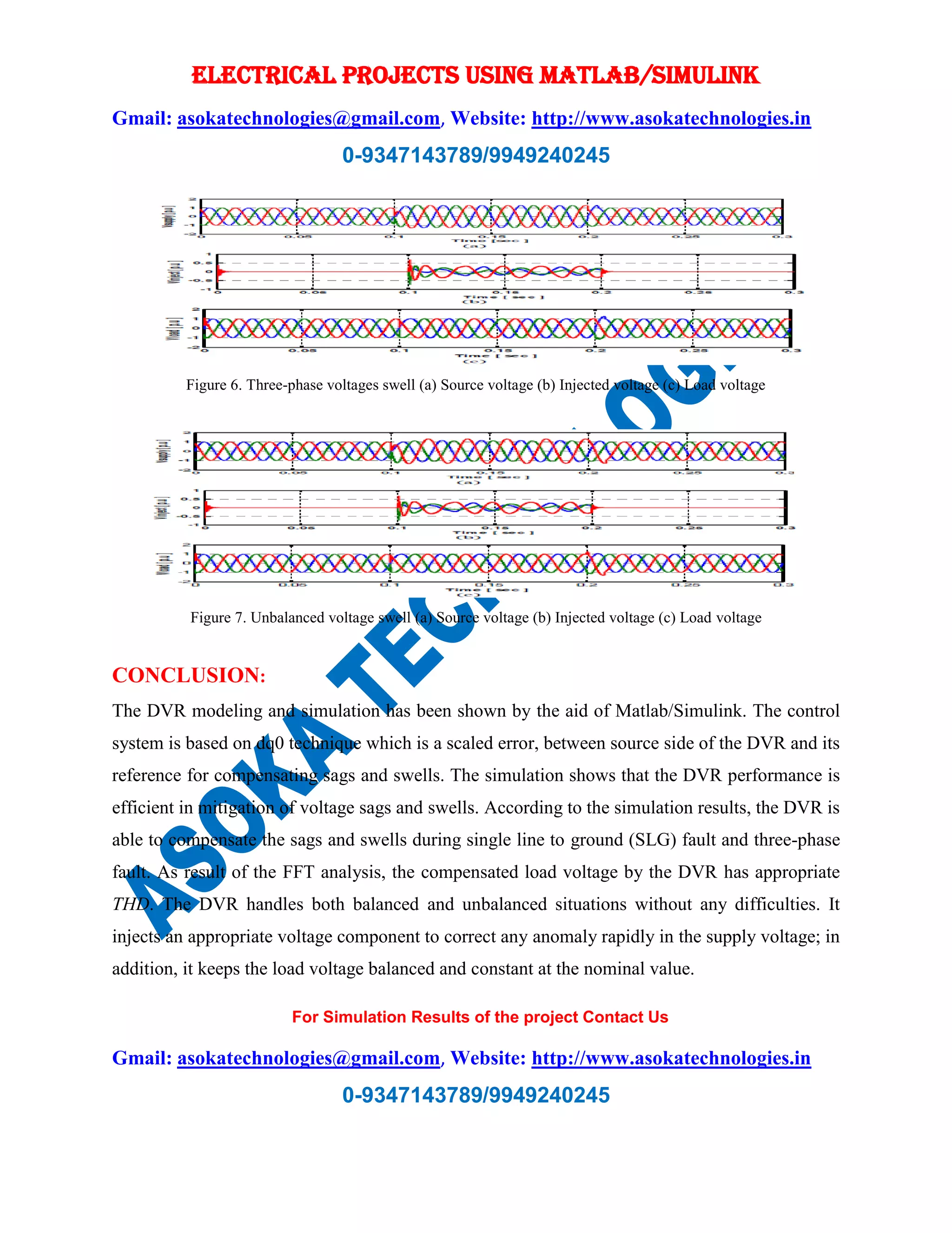
The document discusses the modeling and simulation of a Dynamic Voltage Restorer (DVR) using MATLAB/Simulink to combat voltage sags and swells during single line to ground and three-phase faults. It details a new configuration of the DVR with an improved d-q-0 controller technique, demonstrating through simulation results that it effectively mitigates voltage issues while maintaining a balanced load voltage. The study concludes that the DVR can handle both balanced and unbalanced voltage situations efficiently.