
Recommended
Recommended
More Related Content
What's hot
What's hot (20)
Similar to Assignement 2: Structural Analysis
Similar to Assignement 2: Structural Analysis (20)
More from DavidJPCChai
More from DavidJPCChai (16)
Recently uploaded
Recently uploaded (20)
Assignement 2: Structural Analysis
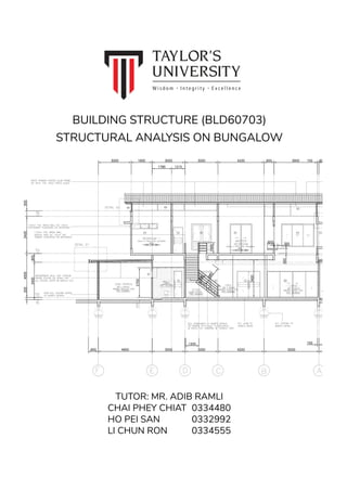
- 1. BUILDING STRUCTURE (BLD60703) STRUCTURAL ANALYSIS ON BUNGALOW TUTOR: MR. ADIB RAMLI CHAI PHEY CHIAT 0334480 HO PEI SAN 0332992 LI CHUN RON 0334555
- 2. TABLE OF CONTENTS 1.0 INTRODUCTION 2.0 ARCHITECTURAL PLANS 2.1 GROUND FLOOR PLAN 2.2 FIRST FLOOR PLAN 2.3 ROOF PLAN 3.0 STRUCTURAL BRIEF 4.0 STRUCTURAL PLANS 4.1 GROUND FLOOR STRUCTURAL PLAN 4.2 FIRST FLOOR STRUCTURAL PLAN 4.3 ROOF STRUCTURAL PLAN 5.0 LOAD DISTRIBUTION PLAN 5.1 GROUND FLOOR LOAD DISTRIBUTION PLAN 5.2 FIRST FLOOR LOAD DISTRIBUTION PLAN 6.0 COLUMN TRIBUTARY AREA DIAGRAMS 6.1 GROUND FLOOR COLUMNS TRIBUTARY AREA DIAGRAM 6.2 FIRST FLOOR COLUMNS TRIBUTARY AREA DIAGRAM 7.0 CHAI PHEY CHIAT - BEAM AND COLUMN ANALYSIS 7.1 SELECTED BEAMS AND COLUMNS 7.2 BEAM ANALYSIS 7.2.1 UNIFORM DISTRIBUTED LOAD 7.2.2 POINT LOAD & UNIFORM DISTRIBUTED LOAD 7.3 COLUMN ANALYSIS 7.3.1 PERIMETER COLUMN 7.3.2 INTERNAL COLUMN 8.0 LI CHUN RON - BEAM AND COLUMN ANALYSIS 8.1 SELECTED BEAMS AND COLUMNS 8.2 BEAM ANALYSIS 8.2.1 UNIFORM DISTRIBUTED LOAD 8.2.2 POINT LOAD & UNIFORM DISTRIBUTED LOAD 8.3 COLUMN ANALYSIS 8.3.1 PERIMETER COLUMN 8.3.2 INTERNAL COLUMN 9.0 REFERENCES
- 3. 1.0 INTRODUCTION The objectives of this project are to introduce us to the basic process of structural design of a two-storey bungalow to gain a holistic structural design experience including the basic concepts in structural design, engineering considerations in building structure, quantification of loads and stresses, as well as the estimation of the sizes of structural members. Through this assignment, we will be able to apply structural theory in designing structural elements, analyse loading conditions using simple mathematical calculation and illustrate the manipulation of loading forces graphically. The chosen building is a two storey bungalow located on Lot 1404, block 16 at Lorong Hua Joo Park 8A1, Kuching Sarawak. The architectural plans were refined and modified leaving only grid lines, dimensions, and room labels. Then a list of drawings were produced in order to suit the requirements of the assignment: 1. Ground Floor Structural Plan 2. First Floor Structural Plan 3. Roof Structural Plan 4. Ground Floor Load Distribution Plan 5. First Floor Load Distribution Plan 6. Roof Load Distribution Plan 7. Ground Floor Tributary Area Plan 8. First Floor Tributary Area Plan 9. Roof Tributary Area Plan Group members were to choose 2 beams and 2 columns in order to conduct the structural analysis and calculations: 1. One (1) beam with only uniform distributed load 2. One (1) beam with point load and uniform distributed load 3. One (1) perimeter column (from roof to ground level) 4. One (1) internal column (from roof to ground floor) It is to produce load diagrams, shear forces diagram and bending moment diagram to clearly illustrates the loads and forces acting on the structure. Also, the column, and the ultimate load for the column is analysed.
- 4. 2.0 ARCHITECTURAL PLANS 2.1 GROUND FLOOR PLAN GROUND FLOOR PLAN SCALE 1:150
- 5. 2.0 ARCHITECTURAL PLANS 2.2 FIRST FLOOR PLAN FIRST FLOOR PLAN SCALE 1:150
- 6. 2.0 ARCHITECTURAL PLANS 2.3 ROOF PLAN ROOF PLAN SCALE 1:150
- 7. 3.0 STRUCTURAL BRIEF Structure Dimension Type 1 Column 0.3m X 0.3m X 0.3m (Length X Width X Height) Type 2 Column 0.15m X 0.4m X 0.3m (Length X Width X Height) Beam 0.15m X 0.3m (Width X Depth) Slab 0.15m (Thickness) Wall 0.15m X 3.0m (Thickness X Height) Dimension of the Structure Standard Weight of Material (Refer to UBBL Fourth Schedule) Material Standard Weight (kN/m³) Reinforced Concrete 24 Brickwork 19 Structure Self-Weight Structure Calculation Self-Weight Type 1 Column 0.3m X 0.3m X 3.0m X 24 kN/m³ 6.5 kN Type 2 Column 0.15m X 0.4m X 3.0m X 24 kN/m³ 4.32 kN Beam 0.15m X 0.3m X 24 kN/m³ 1.08 kN/m Slab 0.15m X 24 kN/m³ 3.6 kN/m² Brick Wall 0.15m X 3.0m X 19 kN/m³ 8.55 kN/m Roof - 1.0 kN/m²
- 8. 4.0 STRUCTURAL PLANS 4.1 GROUND FLOOR STRUCTURAL PLAN GROUND FLOOR STRUCTURAL PLAN SCALE 1:150
- 9. 4.0 STRUCTURAL PLANS 4.2 FIRST FLOOR STRUCTURAL PLAN FIRST FLOOR STRUCTURAL PLAN SCALE 1:150
- 10. 4.0 STRUCTURAL PLANS 4.3 ROOF STRUCTURAL PLAN ROOF STRUCTURAL PLAN SCALE 1:150
- 11. 5.0 LOAD DISTRIBUTION PLANS 5.1 GROUND FLOOR LOAD DISTRIBUTION PLAN GROUND FLOOR LOAD DISTRIBUTION PLAN SCALE 1:150
- 12. 5.0 LOAD DISTRIBUTION PLANS 5.2 FIRST FLOOR LOAD DISTRIBUTION PLAN FIRST FLOOR LOAD DISTRIBUTION PLAN SCALE 1:150
- 13. 5.0 LOAD DISTRIBUTION PLANS 5.3 ROOF LOAD DISTRIBUTION PLAN ROOF LOAD DISTRIBUTION PLAN SCALE 1:150
- 14. 6.0 TRIBUTARY AREA PLANS 6.1 GROUND FLOOR TRIBUTARY AREA PLAN GROUND FLOOR TRIBUTARY AREA PLAN SCALE 1:150
- 15. 6.0 TRIBUTARY AREA PLANS 6.2 FIRST FLOOR TRIBUTARY AREA PLAN FIRST FLOOR TRIBUTARY AREA PLAN SCALE 1:150
- 16. 6.0 TRIBUTARY AREA PLANS 6.3 ROOF TRIBUTARY AREA PLAN ROOF TRIBUTARY AREA PLAN SCALE 1:150
- 17. 7.0 CHAI PHEY CHIAT BEAM AND COLUMN ANALYSIS 7.1 SELECTED BEAMS AND COLUMNS 7.2 BEAM ANALYSIS 7.2.1 UNIFORM DISTRIBUTED LOAD 7.2.2 POINT LOAD & UNIFORM DISTRIBUTED LOAD 7.3 COLUMN ANALYSIS 7.3.1 PERIMETER COLUMN 7.3.2 INTERIOR COLUMN
- 18. 7.0 CHAI PHEY CHIAT - BEAM AND COLUMN ANALYSIS 7.1 SELECTED BEAMS AND COLUMNS Point Load & Uniform Distributed Load Beam E/1-2 Uniform Distributed Load Beam 1b/E-D Perimeter Column Column E1 Interior Column Column E2
- 19. 7.2 BEAM ANALYSIS 7.2.1 UNIFORM DISTRIBUTED LOAD Ground Floor Beam 1b/E-D Ground Floor Beam 1b/E-D carries: ● Dead Load from Beam Self Weight: Gridline E-D ● Dead Load from Brick Wall Weight: Gridline E-D ● Dead Load from Slab: i) Gridline E-D/1-2 ii) Gridline E-D/1b-2 ● Live Load from Slab: i) Gridline E-D/1-2 ii) Gridline E-D/1b-2 Ground Floor Structural Plan Ground Floor Load Distribution Plan
- 20. 7.2.1 UNIFORM DISTRIBUTED LOAD Ground Floor Beam 1b/E-D Beam Self-Weight = 0.15m X 0.3m X 24kN/m³ = 1.08 kN/m Dead Load Brick Wall Weight = 0.15m X 3m X 19kN/m³ = 8.55 kN/m Slab E-D/1-1b = (0.15m X 24kN/m³) X (1.625 / 2) = 2.925 kN/m Slab E-D/1b-2 = (0.15m X 24kN/m³) X (1.525m / 2) = 2.745 kN/m Total Dead Load = (1.08 + 8.55 + 2.925 + 2.745) kN/m = 15.25 kN/m
- 21. 7.2.1 UNIFORM DISTRIBUTED LOAD Ground Floor Beam 1b/E-D Slab E-D/1-1b = 1.5kN/m² X (1.625m / 2) = 1.2188 kN/m Live Load Slab E-D/1b-2 = 1.5kN/m² X (1.525 / 2) = 1.1438 kN/m Total Live Load = (1.2188 + 1.1438) kN/m = 2.3626 kN/m Ultimate Dead Load = 15.25 kN/m X 1.4 = 21.35 kN/m Ultimate Load Ultimate Live Load = 2.3626 kN/m X 1.6 = 3.78 kN/m Total Ultimate Load = (21.35 + 3.78) kN/m = 25.13 kN/m
- 22. 7.2.1 UNIFORM DISTRIBUTED LOAD Ground Floor Beam 1b/E-D 25.13kN/m X 3m = 75.39 kN Resultant Force ∑M = 0 = (Ra X 3) + [ -75.39 X (3/2) ] = 3Ra - 113.09 3Ra = 113.09 Ra = 37.7 kN 37.7kN - 75.39kN = -37.7kN Shear Force Diagram Positive Area 37.7kN X 1.5m X ½ = 28.28 kNm Reaction Force ∑Fy = 0 = Rb + 37.7 + 75.39 Rb = 37.7 kN 37.7kN + (-37.7kN) = 0 kN Bending Moment Diagram Negative Area 37.7kN X 1.5m X ½ = 28.28 kNm Positive Area = Negative Area
- 23. 7.2 BEAM ANALYSIS 7.2.2 POINT LOAD & UNIFORM DISTRIBUTED LOAD Ground Floor Beam E/1-2 Ground Floor Beam E/1-2 carries: ● Dead Load from Beam Self Weight: Gridline 1-2 ● Dead Load from Brick Wall Weight: Gridline 1-2 ● Dead Load from Slab: i) Gridline F-E/1-2 ii) Gridline E-D/1-1b iii) Gridline E-D/1b-2 ● Live Load from Slab: i) Gridline F-E/1-2 ii) Gridline E-D/1-1b iii) Gridline E-D/1b-2 ● Point Load at Point E/1b from Beam 1b/E-D Ground Floor Structural Plan Ground Floor Load Distribution Plan
- 24. 7.2.2 POINT LOAD & UNIFORM DISTRIBUTED LOAD Ground Floor Beam E/1-2 Beam Self-Weight = 0.15m X 0.3m X 24kN/m³ = 1.08 kN/m Dead Load Brick Wall Weight = 0.15m X 3m X 19kN/m³ = 8.55 kN/m Slab F-E/1-2 = (0.15m X 24kN/m³) X (3.15m / 2) X 2/3 = 3.78 kN/m Slab E-D/1-1b = (0.15m X 24kN/m³) X (1.625m / 2) X 2/3 = 1.95 kN/m Total Dead Load for 1-1b = (1.08 + 8.55 + 3.78 + 1.95) kN/m = 15.36 kN/m Slab E-D/1b-2 = (0.15m X 24kN/m³) X (1.525m / 2) X 2/3 = 1.83 kN/m Total Dead Load for 1b-2 = (1.08 + 8.55 + 3.78 + 1.83) kN/m = 15.24 kN/m
- 25. 7.2.2 POINT LOAD & UNIFORM DISTRIBUTED LOAD Ground Floor Beam E/1-2 Slab E-D/1-1b = 1.5kN/m² X (1.625m / 2) X 2/3 = 0.8125 kN/m Live Load Slab E-D/1b-2 = 1.5kN/m² X (1.525 / 2) X 2/3 = 0.7625 kN/m Ultimate Load for 1-1b = (15.36kN/m X 1.4) + (2.3875kN/m X 1.6) = 25.32 kN/m Ultimate Load Ultimate Load for 1b-2 = (15.24kN/m X 1.4) + (2.3375kN/m X 1.6) = 25.08 kN/m Slab F-E/1-2 = 1.5kN/m² X (3.15m / 2) X 2/3 = 1.575 kN/m Total Live Load for 1-1b = (1.575 + 0.8125) kN/m = 2.3875 kN/m Total Live Load for 1b-2 = (1.575 + 0.7625) kN/m = 2.3375 kN/m Point Load from Beam 1b/E-D = 37.7 kN
- 26. 7.2.2 POINT LOAD & UNIFORM DISTRIBUTED LOAD Ground Floor Beam E/1-2 Point Load at Point 1b = 37.7 kN Resultant Force ∑M = 0 = (Ra X 3.15) + (-41.145 X 2.34) + (-37.7 X 1.525) + (-38.247 X 0.7625) = 3.15Ra - 96.28 - 57.49 - 29.16 = 3.15Ra - 182.93 Ra = 58.07 kN 58.07kN - 41.145kN = 16.925 kN Shear Force Diagram Positive Area (58.07 + 16.925) kN X 1.625m X ½ = 74.98kN X 1.625m X ½ = 60.9 kNm Reaction Force ∑Fy = 0 = 58.07 + Rb + (-41.15) + (-37.7) + (-38.25) = Rb - 59.03 Rb = 59.03 kN 16.925kN - 37.7kN = -20.775 kN Bending Moment Diagram Negative Area (20.775 + 59.03)kN X 1.525m X ½ = 79.81kN X 1.525m X ½ = 60.9 kNm Positive Area - Negative Area = 60.9 kNm - 60.9 kNm = 0 kNm -20.775kN - 38.247 kN = -59.03 kN -59.03kN + 59.03 kN = 0 kN Positive Area = Negative Area
- 27. 7.3 COLUMN ANALYSIS 7.3.1 PERIMETER COLUMN Column E/1 No Column at position E/1 Roof Level Dead Load First Floor Level Roof Weight = (3.95m X 1.575m) X 1.0kN/m² = 6.22 kN Roof Beam = (3.95m + 1.575m) X 1.08kN/m = 5.967kN Total Dead Load = 6.22kN + 5.967kN = 12.19 kN Live Load Roof Weight = (3.95m X 1.575m) X 0.5kN/m² = 3.11 kN
- 28. 7.3.1 PERIMETER COLUMN Column E/1 Dead Load Ground Floor Level Concrete Slab = (3.95m X 1.575m) X 3.6kN/m² = 22.4 kN Beam Self Weight = (3.95m + 1.575m) X 1.08kN/m = 5.967kN Brick Wall = (1.5m + 1.575m) X 8.55kN/m = 26.29 kN Live Load Concrete Slab = (3.95m X 1.575m) X 1.5kN/m² = 9.33 kN Column Self Weight = (0.3m X 0.3m X 3m) X 24kN/m³ = 6.48 kN Total Dead Load = (22.4 + 5.967 + 26.29 + 6.48) kN = 61.14 kN Ultimate Load Total Dead Load = 12.19kN + 61.15kN = 73.33 kN Total Live Load = 3.11kN + 9.33kN = 12.44 kN Ultimate Dead Load = 73.33kN X 1.4 = 102.7 kN Total Live Load = 12.44kN X 1.6 = 19.9 kN Total Ultimate Load = 102.7kN + 19.9kN = 122.6 kN
- 29. 7.3.2 INTERIOR COLUMN Column E/2 Roof Level First Floor Level Dead Load Roof Weight = (1.95m X 1.5m) X 1.0kN/m² = 2.925 kN Roof Beam = (1.95m + 1.5m) X 1.08kN/m = 3.726 kN Total Dead Load = 2.925kN + 3.726kN = 6.65 kN Live Load Roof Weight = (1.95m X 1.5m) X 0.5kN/m² = 1.4625 kN Dead Load Concrete Slab = (1.95m X 1.5m) X 3.6kN/m² = 10.53 kN Beam Self Weight = (3.95m + 3.525m) X 1.08kN/m = 8.073 kN Brick Wall = (1.95m + 1.5m) X 8.55kN/m = 29.5 kN Column Self Weight = (0.15m X 0.4m X 3m) X 24kN/m³ = 4.32 kN Roof Weight = (1.575m X 1.5m + 2.45m X 3.525) kN X 1.0kN/m² = 11.0 kN Total Dead Load = (10.53 + 11.0 + 8.073 + 29.5 + 4.32) kN = 63.42 kN
- 30. 7.3.2 INTERIOR COLUMN Column E/2 First Floor Level Live Load Concrete Slab = (1.95m X 1.5m) X 1.5kN/m² = 4.39 kN Roof Weight = (1.575m X 1.5m + 2.45m X 3.525m) X 0.5kN/m = 5.5 kN Total Live Load = 4.39kN + 5.5kN = 9.89 kN Ground Floor Level Dead Load Concrete Slab = (3.95 X 1.575 + 1.5 X 1.95)m² X 3.6kN/m² = 32.93 kN Beam Self Weight = (3.95m + 3.525m) X 1.08kN/m = 8.073 kN Brick Wall = (3.525m + 1.5m + 0.5m) X 8.55kN/m = 47.24 kN Column Self Weight = (0.15m X 0.4m X 3m) X 24kN/m³ = 4.32 kN Total Dead Load = (32.93 + 8.073 + 47.24 + 4.32) kN = 92.56 kN
- 31. 7.3.2 INTERIOR COLUMN Column E/2 Ground Floor Level Live Load Concrete Slab = (3.95 X 1.575 + 1.5 X 1.95)m² X 1.5kN/m² = 13.72 kN Total Live Load = 13.72 kN Ultimate Load Total Dead Load = 6.65kN + 63.42kN + 92.56kN = 162.63 kN Total Live Load = 1.4625kN + 9.89kN + 13.72kN = 25.07 kN Ultimate Dead Load = 162.63kN X 1.4 = 227.68 kN Total Live Load = 25.07kN X 1.6 = 40.11 kN Total Ultimate Load = 227.68kN + 40.11kN = 267.79 kN
- 32. 8.0 LI CHUN RON BEAM AND COLUMN ANALYSIS 8.1 SELECTED BEAMS AND COLUMNS 8.2 BEAM ANALYSIS 8.2.1 UNIFORM DISTRIBUTED LOAD 8.2.2 POINT LOAD & UNIFORM DISTRIBUTED LOAD 8.3 COLUMN ANALYSIS 8.3.1 PERIMETER COLUMN 8.3.2 INTERIOR COLUMN
- 33. 8.0 LI CHUN RON - BEAM AND COLUMN ANALYSIS 8.1 SELECTED BEAMS AND COLUMNS Point Load & Uniform Distributed Load Beam D/2-3 Uniform Distributed Load Beam 2B/E-D Perimeter Column Column E3 Interior Column Column D3
- 34. 8.2 BEAM ANALYSIS 8.2.1 UNIFORM DISTRIBUTED LOAD First Floor Beam 2B/E-D First Floor Beam 2B/E-D carries: ● Dead Load from Beam Self Weight: Gridline E-D ● Dead Load from Brick Wall Weight: Gridline E-D ● Dead Load from Slab: i) Gridline E-D/2-2B ii) Gridline E-D/2B-3 ● Live Load from Slab: i) Gridline E-D/2-2B ii) Gridline E-D/2B-3 First Floor Structural Plan First Floor Load Distribution Plan
- 35. 8.2.1 UNIFORM DISTRIBUTED LOAD First Floor Beam 2B/D-E Beam Self-Weight = 0.15m X 0.3m X 24kN/m³ = 1.08 kN/m Dead Load Brick Wall Weight = 0.15m X 3m X 19kN/m³ = 8.55 kN/m Slab E-D / 2-2B = (0.15m X 24kN/m³) X (2.300m / 2) = 4.14 kN/m Slab E-D / 2B-3 = (0.15m X 24kN/m³) X (1.870m / 2) = 3.366 kN/m Total Dead Load = (1.08 + 8.55 + 4.14 + 3.366) kN/m = 17.136 kN/m
- 36. 8.2.1 UNIFORM DISTRIBUTED LOAD First Floor Beam 2B/D-E Slab D-E/2-2B = 1.5kN/m² X (2.300m / 2) = 1.725 kN/m Live Load Slab D-E/2B-3 = 1.5kN/m² X (1.870m / 2) = 1.403 kN/m Total Live Load = (1.725 + 1.403kN/m) = 3.128 kN/m Ultimate Dead Load = 17.136 kN/m X 1.4 = 23.9904 kN/m Ultimate Load Ultimate Live Load = 3.128 kN/m X 1.6 = 5.0048 kN/m Total Ultimate Load = (23.9904kN/m + 5.0048kN/m) = 28.9952 kN/m
- 37. 8.2.1 UNIFORM DISTRIBUTED LOAD First FLoor Beam D-E / 2B (Ra x 3.000) - (28.9952 x 3.000) x (3.000 ÷ 2) 3.000Ra = 130.478 Ra = 43.49 kN 43.49 kN - 86.9856 kN = -43.49 kN Shear Force Diagram Positive Area 43.39 kN X 1.5m X ½ = 32.54 kNm Reaction Force 43.49 kN + (-43.49 kN) = 0 kN Bending Moment Diagram Negative Area 43.39 kN X 1.5m X ½ = 32.54 kNm Positive Area = Negative Area 43.49 - (28.9952 x 3.00) Rb = 0 Rb = 43.49 kN Resultant Force 28.9952 kN/m x3m =86.9856 kN 0 kN ( + ) ( - ) Ra = 43.49 kN 43.49 kN + (-43.49 kN) = 0 kN 43.49 kN - 86.9856 kN = -43.49 kN 0 kN 0 kN 32.52 kNm
- 38. First Floor Structural Plan First Floor Load Distribution Plan 8.2 BEAM ANALYSIS 8.2.2 POINT LOAD & UNIFORM DISTRIBUTED LOAD First Floor Beam D/2-3 First Floor Beam D/2-3 carries: ● Dead Load from Beam Self Weight: Gridline 2-3 ● Dead Load from Brick Wall Weight: Gridline 2-3 ● Dead Load from Slab: i) Gridline E-D / 2-2B ii) Gridline E-D / 2B-3 iii) Gridline D-C / 1C-3 ● Live Load from Slab: i) Gridline E-D / 2-2B ii) Gridline E-D / 2B-3 iii) Gridline D-C / 1C-3 ● Point Load at D / 2B from Beam 2B / E-D
- 39. 8.2.2 POINT LOAD & UNIFORM DISTRIBUTED LOAD First Floor Beam D / 2-3 Beam Self-Weight = 0.15m X 0.3m X 24kN/m³ = 1.08 kN/m Dead Load Brick Wall Weight = 0.15m X 3m X 19kN/m³ = 8.55 kN/m Slab D-C / 1C-3 = (0.15m X 24kN/m³) X (5.1m / 2) X 2/3 = 6.12 kN/m Slab E-D / 2-2B = (0.15m X 24kN/m³) X (2.030m / 2) X 2/3 = 2.436 kN/m Total Dead Load for 2-2B = (1.08 + 8.55 + 6.12 + 2.436) kN/m = 18.186 kN/m Slab E-D / 2B-3 = (0.15m X 24kN/m³) X (1.870m / 2) X 2/3 = 2.244 kN/m Total Dead Load for 2B-3 = (1.08 + 8.55 + 6.12 + 2.244) kN/m = 17.994 kN/m
- 40. 8.2.2 POINT LOAD & UNIFORM DISTRIBUTED LOAD First Floor Beam D / 2-3 Slab E-D / 2-2B = 1.5kN/m² X (1.625m / 2) X 2/3 = 0.8125 kN/m Live Load Slab E-D / 2B-3 = 1.5kN/m² X (1.525 / 2) X 2/3 = 0.7625 kN/m Ultimate Load for 2-2B = (18.186kN/m X 1.4) + (3.3625kN/m X 1.6) = 30.8404kN/m Ultimate Load Ultimate Load for 2B-3 = (17.994kN/m X 1.4) + (3.3125kN/m X 1.6) = 30.4916kN/m Slab D-C / 1C-3 = 1.5kN/m² X (5.1m / 2) X 2/3 = 2.55 kN/m Total Live Load for 2-2B = (2.55 + 0.8125) kN/m = 3.3625 kN/m Total Live Load for 2B-3 = (2.55 + 0.7625) kN/m =3.3125 kN/m Point Load from Beam 2B / E-D = 43.49 kN
- 41. 8.2.2 POINT LOAD & UNIFORM DISTRIBUTED LOAD Ground Floor Beam D / 2-3 Point Load at Point 2B / E-D = 43.39 kN Resultant Force ∑M = 0 = (Ra X 3.9) + (-62.606 X 2.9) + (-43.49 X 1.95) + (-57.019 X 0.935) = 3.9Ra - 181.6 - 84.8 - 53.3 = 3.9Ra - 318.7 Ra = 81.72 kN 81.72kN - 62.6kN = 19.12 kN Shear Force Diagram Positive Area (81.72 + 19.12) kN X 2.030m X ½ = 100.84kN X 2.030m X ½ = 102.4 kNm Reaction Force ∑Fy = 0 = 81.72 + Rb + (-62.6) + (-43.49) + (-57.02) = Rb - 81.39 Rb = 81.39kN 19.12kN - 43.49kN = -24.37 kN Bending Moment Diagram Negative Area (24.37 + 81.39)kN X 1.870m X ½ =105.8kN X 1.870m X ½ = 98.9 kNm Positive Area - Negative Area = 102.4 kNm - 98.9 kNm = 3.5 kNm = 0 -24.37kN - 57.02kN = -81.39 kN -81.39kN + 81.39kN = 0 kN Positive Area = Negative Area ( + ) ( - ) Ra = 81.72 kN 19.12kN - 43.49kN = -24.37 kN 0 kN 0 kN 102.4 kNm 0 kN 0 kN Rb = 81.39 kN 81.72kN - 62.6kN = 19.12 kN
- 42. 8.3 COLUMN ANALYSIS 8.3.1 PERIMETER COLUMN Column E / 3 Dead Load Beam : (3.0 + 1.95 + 1.95 + 2.55) x 0.15 x 0.45 x 24 = 15.3kN Roof : 3.0 x (1.95 + 2.55) x 1.0kN/m2 =13.5kN Total Dead load = 28.8kN Live Load Slab: (1.95 + 2.55) x 3 x 0.5kN/m2 =6.75kN Ultimate Load: =(1.4 x 28.8) + (1.6 x 6.75) = 40.32 + 10.8 = 51.12kN Roof Level Dead Load Beam : 24kN/m2 x 0.15 x 0.45 x (5.1 + 1.9 + 1.8) =14.28kN Slab : 24kN/m2 x 0.15 x 5.1 x 3.7 =67.9kN Brick Wall: 19kN/m2 x 0.15 x 3m x (5.1 + 1.9 + 1.8) =74.8 Total Dead load = 67.9 + 14.26 + 74.8 =156.96kN Live Load Slab: 1.5kN/m2 x 0.15 x 5.1 x 3.7 =4.24kN Ultimate Load: (1.4 x 156.96kN) + (1.6 x 4.24kN) = 219.7 + 6.8 = 226.5kN First Floor Level
- 43. 8.3.1 PERIMETER COLUMN Column E / 3 Ground Floor Level Ultimate Load Total Dead Load = 96.56kN + 28.8kN + 156.9kN = 282.26 kN Total Live Load = 14.175kN + 4.24kN + 6.75kN = 25.165kN Ultimate Dead Load = 282.26kN X 1.4 = 395.164 kN Total Live Load = 25.165kN X 1.6 = 40.264 kN Total Ultimate Load = 395.164kN + 40.264kN = 435.428 kN Dead Load Beam : (1.95 + 1.2 + 3.0) x 0.15 x 0.45 x 24 =9.96kN Slab : (1.95 + 1.2) x 3.0 x 0.15 x 24 =34.02kN Brick Wall: (1.95 + 1.2 + 3.0) x 0.15 x 19 x 3 =52.58kN Total Dead load = 96.56kN Live Load Slab: (1.95 + 1.2) x 3.0 x 1.5 =14.175kN Ultimate Load: (1.4 x 96.56kN) + (1.6 x 14.175kN) =135.18 + 22.68 =157.86kN
- 44. 8.3.2 INTERIOR COLUMN Column D / 3 Roof Level Dead Load Beam : 24kN2 x 0.15 x 0.45 x (3.0 + 4.5) =12.15kN Roof : 1.0kN/m2 x 3.0 x 4.5 =13.5kN Total Dead load = 13.5kN + 12.15kN =25.65kN Live Load Roof: 0.5kN/m2 x 4.5 x 3.0 =6.75kN Ultimate Load: =(1.4 x 25.65) + (1.6 x 6.75) = 35.91 + 10.8 =46.71kN Dead Load Beam : 24kN2 x 0.15 x 0.45 x (3.0 + 3.9 + 1.2) =9.72kN Slab : 24kN/m2 x 0.15m x 3.9 x 1.2 =16.8kN Brick Wall: 19kN/m2 x 0.15m x 3m x (1.95 + 1.2 +1.95 +3.0) =16.65kN Total Dead load = 16.8 + 9.72 + 16.65 =43.17 Live Load Slab: 1.5kN/m2 x 0.15m x 5.1 x 3.0 =3.44kN Ultimate Load: =(1.4 x 43.17) + (1.6 x 3.44) =60.4 + 5.5 =65.9kN First Floor Level
- 45. 8.3.2 INTERIOR COLUMN Column D / 3 Ground Floor Level Ultimate Load Total Dead Load = 25.65kN + 43.17kN + 137.5kN = 206.32 kN Total Live Load = 3.44kN + 3.44kN + 6.75kN = 13.63 kN Ultimate Dead Load = 206.32kN X 1.4 = 288.85 kN Total Live Load = 13.63kN X 1.6 = 21.80 kN Total Ultimate Load = 288.85kN + 21.80kN = 310.65 kN Dead Load Beam : 24kN2 x 0.15 x 0.45 x (3.0 + 3.9 + 1.2) =9.72kN Slab : 24kN/m2 x 0.15m x 5.1 x 3.0 =55.08kN Brick Wall: 19kN/m2 x 0.15m x 3m x (3.0 + 3.9 + 1.2) =69.3kN Total Dead load = 55.08 + 13.12 + 69.3 =137.5kN Live Load Slab: 1.5kN/m2 x 0.15m x 5.1 x 3.0 =3.44kN Ultimate Load: =(1.4 x 137.5) + (1.6 x 3.44) =192.5 + 5.5 =198kN
- 46. 9.0 REFERENCES Malaysia.; International Law Book Services. Legal Research Board, Uniform Building By Law 1984. Kuala Lumpur : International Law Book Services, 2013.