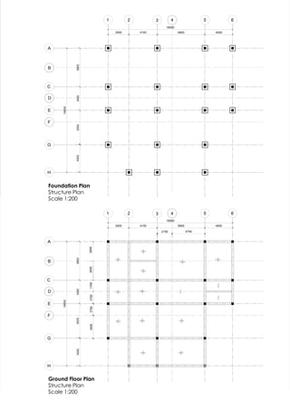
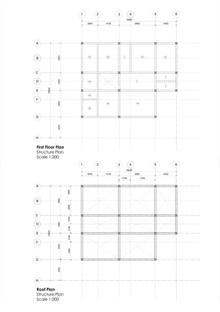
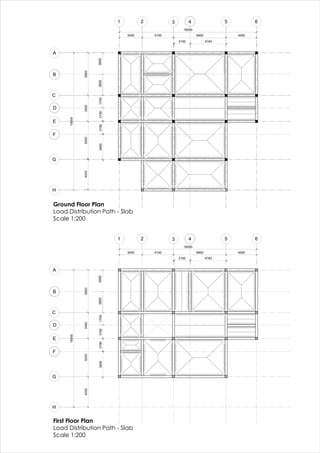
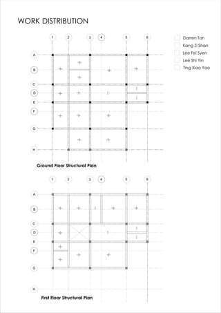
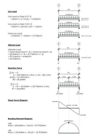
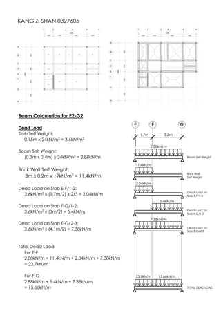
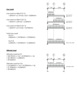
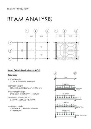
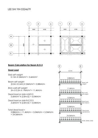
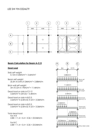
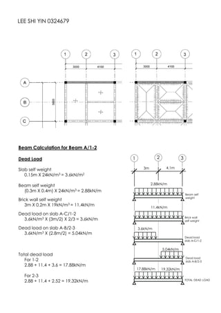
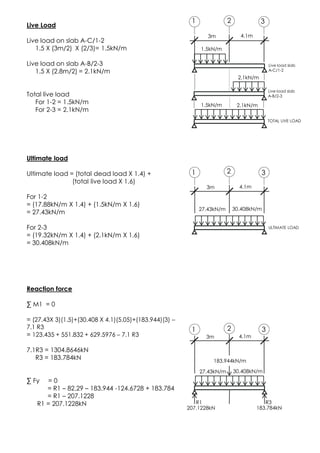
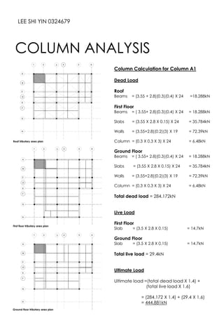
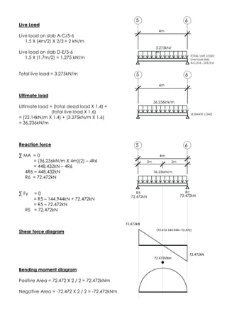
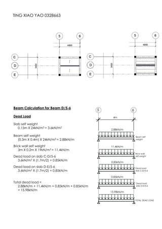
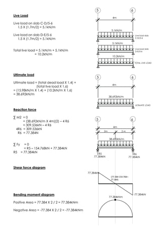
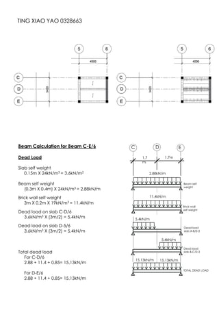
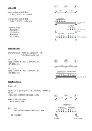
This document outlines a group project to analyze the structural components of a two-storey bungalow. The group was tasked with designing the bungalow floor plans using preset geometric shapes and ensuring certain room requirements were met. They then had to produce structural drawings and individually analyze specific beams and columns based on the design. Calculations were shown for several beams, applying formulas to determine dead loads, live loads, reaction forces, shear forces, and bending moments. The analyses followed the prescribed process and provided the necessary structural information and calculations.


![2.1 CALCULATION FORMULA
UBBL Factor
Density of RC (reinforced concrete) = 24kN/m3
Density of Brick = 19kN/m3
Live Load in House = 15kN/m3
Assumption
ALL BEAM DIMENSIONS ARE FIXED AT 300mm x 400mm
ALL COLUMN ARE FIXED AT 300mm x 300mm
ALL SLAB THICKNESS ARE FIXED AT 150mm
ALL WALL THICKNESS ARE FIXED AT 200mm, HEIGHT AT 3000mm
Note: x-axis (right), y-axis (up), moment (clockwise) is positive
Slab System
Ly = Longer side of slab When Ly/ Lx > 2 (one way slab system)
Lx = Shorter side of slab When Ly/ Lx <2 or = 2 (two way slab system)
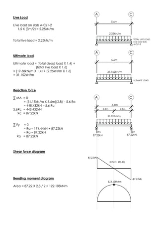
Beam Calculations
Beam self weight = material density x size of beam
Dead load on slab = material density x thickness x Lx/2 one way / two way trapezoidal
= [ material density x thickness x Lx/2 ]x 2/3 two way triangular slab
Brick wall self weight = material density x thickness x height
Live load on slab = UBBL live load factor x Lx/2 one way/ two way trapezoidal slab
= [ UBBL live load factor x Lx/2 ] x 2/3 two way triangular slab
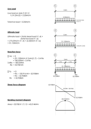
Ultimate load = ( Total dead load x 1.4) + (Total live load x 1.6)
Reaction force =
=
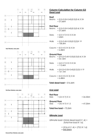
Column Calculation
Brick wall self weight = material density x thickness x height x total length of walls in tributary area
Slab self weight = material density x thickness x area of tributary area
Beam self weight = material density x size of column x height of column
Live load on slab = (Total dead load x 1.4) + ( Total live load x 1.6)
Capacity of concrete (N) = 0.4fcuAc + 0.8 fyAsc
DESIGN
BRIEF2
= capacity of concrete
= concrete strength (N/mm2)
= cross section of concrete column
= yield strength of steel ( N/mm2)
= steel content in a column](https://image.slidesharecdn.com/bstructurefinalfinal-180704133728/85/B-structure-final-final-4-320.jpg)


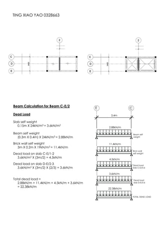
![Reaction Force
∑ Me = 0
0 = (-Rg x 5m) + [(39.46kN/m x 1.7m) x 0.8m]
+ (50.634kN x 1.7m)
+ [(30.44kN/m x 3.3m) x 3.35m]
5Rg = 57.0197 + 86.0778 + 336.5142
Rg = 95.9223kN
∑ Fy = 0
0 = Re - 67.082 - 50.634 - 100.452 + 95.9223
Re = 122.2457kN
Shear Force Diagram
X/3.3 = 4.5297/(4.5297+95.9223)
100.452X = 14.948
X = 0.148
Bending Moment Diagram
+ve Area:
[(122.2457 + 55.1637) x 1.7/2] + (4.5297 x 0148/2)
= 150.798 + 0.3357
= 151.3309kNm
-ve Area:
(-95.9223) x (3.3-0.148)/2
= -95.9223 x 1.576
= -151.17kNm
-95.9223kN
151kNm
122.2457kN 95.9223kN
39.46kN/m
Re Rg
3.3m
E GF
1.7m
30.44N/m
50.634kN
122.2457kN
55.1637kN
4.5297kNX
3.3
4.5297
95.9223](https://image.slidesharecdn.com/bstructurefinalfinal-180704133728/85/B-structure-final-final-26-320.jpg)
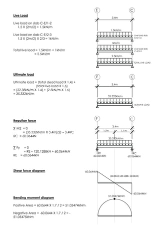
![Reaction Force
∑ M1 = 0
0 = (-R3 x 7.1m) + [(27.432kN/m x 3m) x 1.5m]
+ (95.9223kN x 3m)
+ [(30.416kN/m x 4.1m) x 5.05m]
7.1R3 = 123.44 + 287.77 + 624.4628
R3 = 145.87kN
∑ Fy = 0
0 = R1 - 82.296 - 95.9223 - 123.656 + 145.87
R1 = 156.0043kN
Shear Force Diagram
Bending Moment Diagram
+ve Area:
(156.0043 + 73.7083) x 3/2]
= 344.5689kNm
-ve Area:
(-145.87 - 22.214) x 4.1/2
= -344.5722kNm
-145.87kN
344kNm
156.0043kN 145.87kN
27.43kN/m
R1 R2
4.1m
1 32
3m
30.16N/m
95.9223kN
156.0043kN
73.7083kN
-22.214kN](https://image.slidesharecdn.com/bstructurefinalfinal-180704133728/85/B-structure-final-final-29-320.jpg)
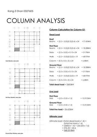
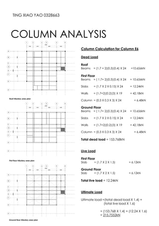
![Column Calculation for Column E3
Dead Load
Roof
Beams = (3.55+1.7+3.45+2.5)(0.3)(0.4) x 24
= 32.256kN
First Floor
Beams = (3.55+1.7+3.45+2.5)(0.3)(0.4) x 24
= 32.256kN
Slabs = [(2.5 x 3.45)+(3.55 x 2.5)+(1.7 x 3.45)] x 24
= 84.114kN
Walls = (3.55+2.5)(0.2)(3)x 19
= 68.97kN
Column = (0.3 x 0.3 x 3) x 24
= 6.48kN
Ground Floor
Beams = (3.55+1.7+3.45+2.5)(0.3)(0.4) x 24
= 32.256kN
Slabs = (3.55+3.45)(1.7+2.5)(0.15) x 24
= 105.84kN
Walls = (3.55+3.45+2.5)(0.2)(3) x 19
= 108.3kN
Column = (0.3 x 0.3 x 3) x 24
= 6.48kN
Total dead load = 476.952kN
Live Load
First Floor
Slab = (5.865+8.625+8.875) x 1.5 = 35.0475kN
Ground Floor
Slab = (7 x 4.2) x 1.5 = 44.1kN
Total live load = 79.1475kN
Ultimate Load
Ultimate load =(total dead load x 1.4) +
(total live load x 1.6)
= (476.952 x 1.4) + (79.1475 x 1.6)
= 667.7328 + 126.636
= 794.3688kN
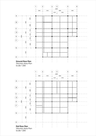
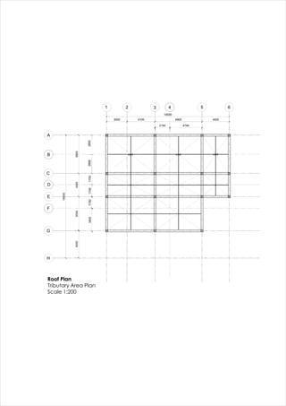
Roof tributary area plan
First floor tributary area plan
Ground floor tributary area plan
Kang Zi Shan 0327605](https://image.slidesharecdn.com/bstructurefinalfinal-180704133728/85/B-structure-final-final-31-320.jpg)

![Shear Force Diagram
175.642kN – 82.29kN = 93.352kN
93.352kN – 129.93kN = -36.578kN
-36.578kN – 123.66kN = -160.238kN
-160.238kN + 160.238kN = 0
Bending Moment Diagram
+ve
Area = [3(175.642+93.352)]/2 = 430.491kNm
-ve
Area = [4.1(36.578+160.238)]/2 = 430.473kNm
175.642kN
-160.238kN
403.8kNm
(93.352-129.93)
(175.642-82.29)93.352kN
-36.578kN
3m 4.1m
-ve
+ve](https://image.slidesharecdn.com/bstructurefinalfinal-180704133728/85/B-structure-final-final-38-320.jpg)
![Column Calculation for Column C1
Dead Load
Roof
Beams = (2.8+1.7+3.55+2.8+1.7)(0.3)(0.4) X 24
=36.144kN
First Floor
Beams = (2.8+1.7+3.55+2.8+1.7)(0.3)(0.4) X 24
= 36.144kN
Slabs = [(2.8X3.55)+(3X1.7)] X 0.15 X 24
= 54.144kN
Walls = (3.55+2.8+1.7+2.8+1.7)(0.2)(3) X 19
= 143.07kN
Column = (0.3 X 0.3 X 3) X 24 = 6.48kN
Ground Floor
Beams = (2.8+1.7+3.55+2.8+1.7)(0.3)(0.4) X 24
= 36.144kN
Slabs = (4.5X3.55) X 0.15 X 24 = 57.51kN
Walls = (3.55+2.8+1.7+2.8+1.7)(0.2)(3) X 19
= 143.07kN
Column = (0.3 X 0.3 X 3) X 24 = 6.48kN
Total dead load = 519.186kN
Live Load
First Floor
Slab = [(2.8X3.55) + (3X1.7)] X 1.5 = 22.56kN
Ground Floor
Slab = (4.5X3.55) X 1.5 = 23.96kN
Total live load = 46.52kN
Ultimate Load
Ultimate load =(total dead load X 1.4) +
(total live load X 1.6)
= (519.186 X 1.4) + (46.52 X 1.6)
= 801.292kN
COLUMN ANALYSIS
LEE FEI SYEN 0323008
Roof tributary area plan
First floor tributary area plan
Ground floor tributary area plan](https://image.slidesharecdn.com/bstructurefinalfinal-180704133728/85/B-structure-final-final-41-320.jpg)
![Shear Force Diagram
183.9kN – 114.3kN = 69.644kN
69.644kN – 83.7kN = -14.056kN
-14.056kN – 157.496kN = -171.496kN
-171.496kN + 171.496kN = 0
Bending Moment Diagram
+ve
Area = [3(185.94+69.64)]/2 = 380.38kNm
-ve
Area = [4.1(14.056+171.496)]/2 = 380.381kNm
183.94kN
-171.496kN
380.376kNm
(69.644-83.7)
(183.94 –114.3)69.644kN
-14.056kN
3m 4.1m
-ve
+ve](https://image.slidesharecdn.com/bstructurefinalfinal-180704133728/85/B-structure-final-final-49-320.jpg)
![Shear Force Diagram
207.1228kN – 82.29kN = 124.8328kN
124.8324kN – 183.944kN = -59.1112kN
-59.1112kN – 124.6728kN = -183.784kN
-183.784kN + 183.784kN = 0
Bending Moment Diagram
+ve
Area = [3(124.8328+ 207.1228)]/2 = 497.9334kNm
-ve
Area = [4.1(183.784+59.1112)]/2 = 497.935kNm
3m 4.1m
207.1228kN
-183.784kN
(124.883-183.944)
(207.1228 – 82.29)124.8328kN
-59.1112kN
497.935kNm
-ve
+ve](https://image.slidesharecdn.com/bstructurefinalfinal-180704133728/85/B-structure-final-final-52-320.jpg)
![Column Calculation for Column C3
Dead Load
Roof
Beams = (2.8+1.7+3.45+3.5)(0.3)(0.4) X 24
=18.288kN
First Floor
Beams = (2.8+1.7+3.45+3.5)(0.3)(0.4) X 24
=18.288kN
Slabs = [(6.95 x 2.8)+(1.7 x 3.45] X 24
= 91.17kN
Walls = (2.8+3.45+3.5)(0.2)(3)X 19
= 72.39kN
Column = (0.3 X 0.3 X 3) X 24
= 6.48kN
Ground Floor
Beams = (2.8+1.7+3.45+3.5)(0.3)(0.4) X 24
=18.288kN
Slabs = (6.95 X 4.2 X 0.15) X 24
= 105.084kN
Walls = (2.8+3.45+3.5)(0.2)(3) X 19
= 111.15kN
Column = (0.3 X 0.3 X 3) X 24
= 6.48kN
Total dead load = 530.442kN
Live Load
First Floor
Slab = [(6.95 x 2.8)+(1.7 x 3.45)] X1.5 = 37.9875kN
Ground Floor
Slab = (6.95 x 4.2) X 1.5 = 43.785kN
Total live load = 81.7725kN
Ultimate Load
Ultimate load =(total dead load X 1.4) +
(total live load X 1.6)
= (530.442 X 1.4) + (81.7725 X 1.6)
= 873.4548kN
Roof tributary area plan
First floor tributary area plan
Ground floor tributary area plan](https://image.slidesharecdn.com/bstructurefinalfinal-180704133728/85/B-structure-final-final-54-320.jpg)
![Shear Force Diagram
88.53kN – 49.844kN = 38.686kN
38.686kN – 77.384kN = -38.738kN
-38.738kN – 49.844kN = -88.582kN
-88.582kN + 88.582kN = 0
Bending Moment Diagram
+ve
Area = [1.7(88.53+38.686)]/2 = 108.1136kNm
-ve
Area = [1.7(-38.738-88.582)]/2 = -108.222kNm
88.53kN
-88.582kN
108.1336kNm
(38.686-77.384)
(88.53-49.844)38.686kN
-38.738kN
1.7m 1.7m
-ve
+ve](https://image.slidesharecdn.com/bstructurefinalfinal-180704133728/85/B-structure-final-final-61-320.jpg)
![Column Calculation for Column E5
Dead Load
Roof
Beams = (2+1.7+3.45+2.5)(0.3)(0.4) X 24
=27.792kN
First Floor
Beams = (2+1.7+3.45+2.5)(0.3)(0.4) X 24
=27.792kN
Slabs = [(2.5 x 3.45)+(3.45 x 1.7)+(2X1.7)] X 24
X0.15
= 64.404kN
Walls = (2+1.75+3.45)(0.2)(3)X 19
= 133.722kN
Column = (0.3 X 0.3 X 3) X 24
= 6.48kN
Ground Floor
Beams = (2+1.7+3.45+2.5)(0.3)(0.4) X 24
=27.792kN
Slabs = [(2.5 x 3.45)+(3.45 x 1.7)+(2X1.7)] X 24
X0.15
= 64.404kN
Walls = (2+1.75+3.45)(0.2)(3)X 19
= 133.722kN
Column = (0.3 X 0.3 X 3) X 24
= 6.48kN
Total dead load = 492.588kN
Live Load
First Floor
Slab = [(2.5 x 3.45)+(1.7 x 3.45)+(2X1.7)] X1.5 =
26.835kN
Ground Floor
Slab = [(2.5 x 3.45)+(1.7 x 3.45)+(2X1.7)] X1.5 =
26.835kN
Total live load = 53.67kN
Ultimate Load
Ultimate load =(total dead load X 1.4) +
(total live load X 1.6)
= (492.588 X 1.4) + (53.67 X 1.6)
= 775.4952kN
Roof tributary area plan
First floor tributary area plan
Ground floor tributary area plan](https://image.slidesharecdn.com/bstructurefinalfinal-180704133728/85/B-structure-final-final-65-320.jpg)


