Downloaded 142 times

![24/2/2013
CE370 Prof. A.harif 15
24/2/2013 February CE 370: Prof. A. Charif 29
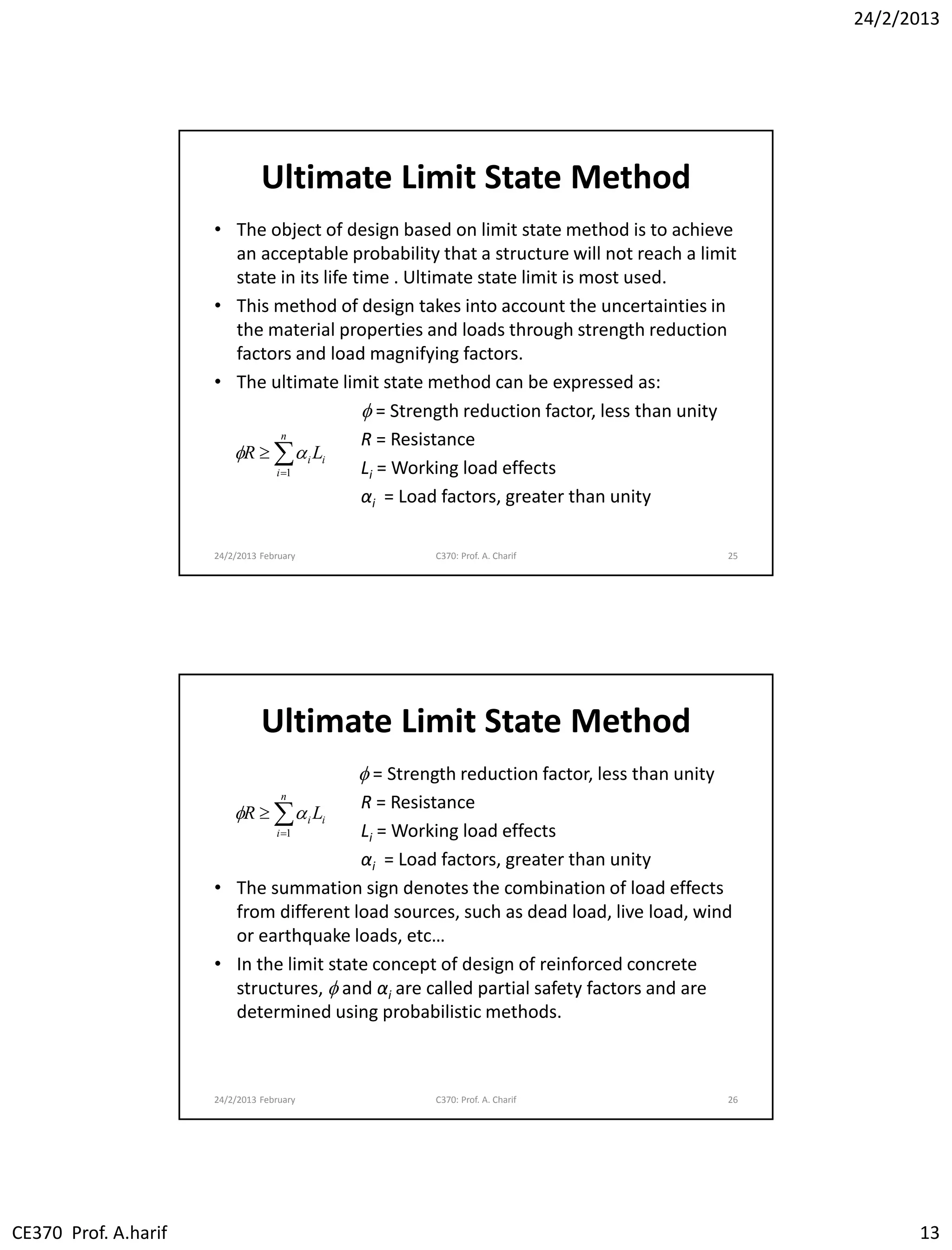
Strength Reduction Factors f
[1] Axial Tension f = 0.90
[2] Flexure f = 0.90
[3] Axial Compression w or w/o flexure
(a) Member w/ spiral reinforcement f = 0.70
(b) Other reinforcement members f = 0.65
[4] Shear and Torsion f = 0.75
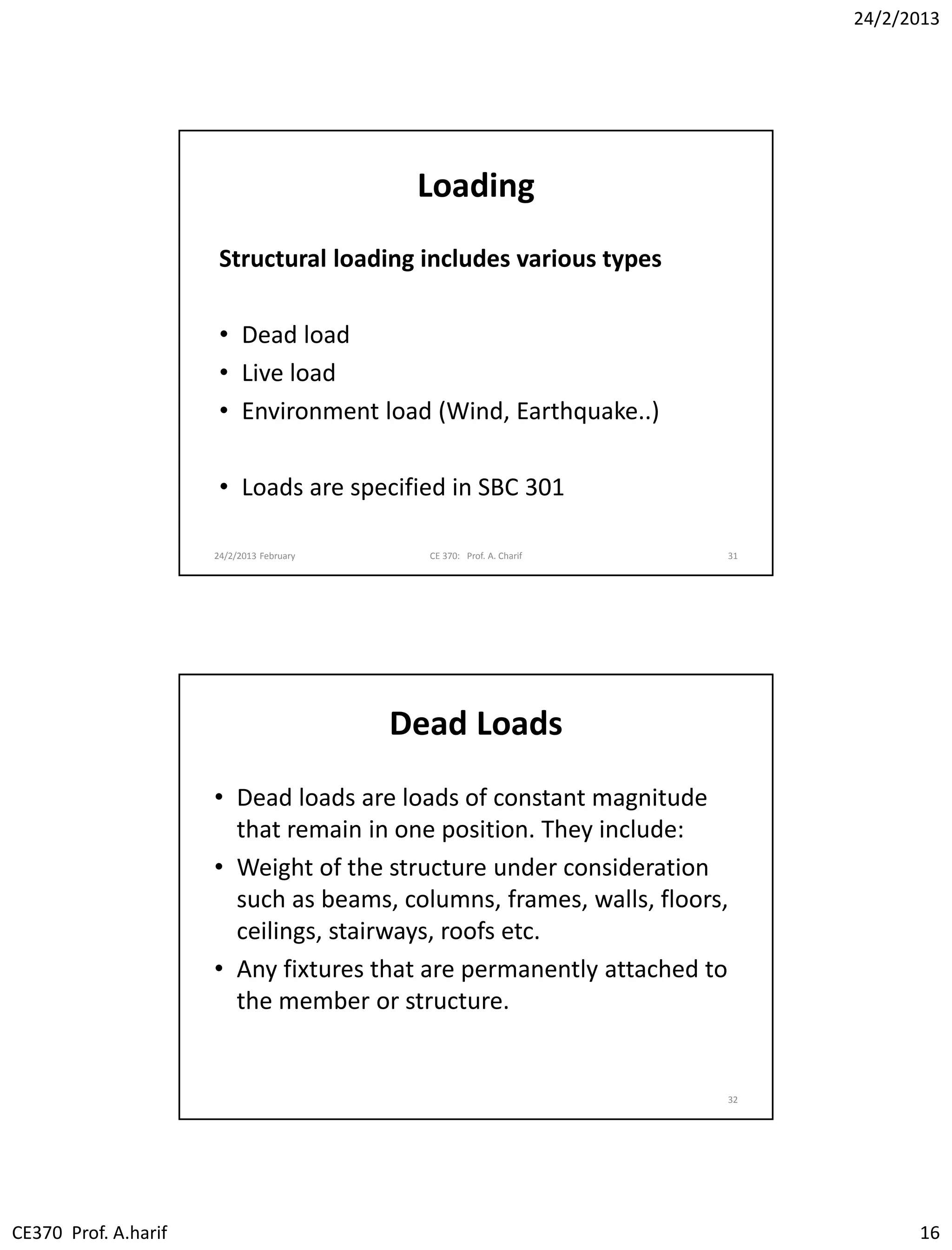
LOADING
• Accurate estimation of the loads that may be
applied on a structure during its life is very
important. It is a difficult task faced by the
structural designer.
• No load that is reasonably expected to occur
should be ignored.
• After loads are estimated, the next problem is
to decide the worst possible combinations of
these loads that might occur at one time.
30](https://image.slidesharecdn.com/2-introductiontorccodesandlimitstates-170818222730/75/Lec01-Introduction-to-RC-Codes-and-Limit-States-Reinforced-Concrete-Design-I-Prof-Abdelhamid-Charif-15-2048.jpg)


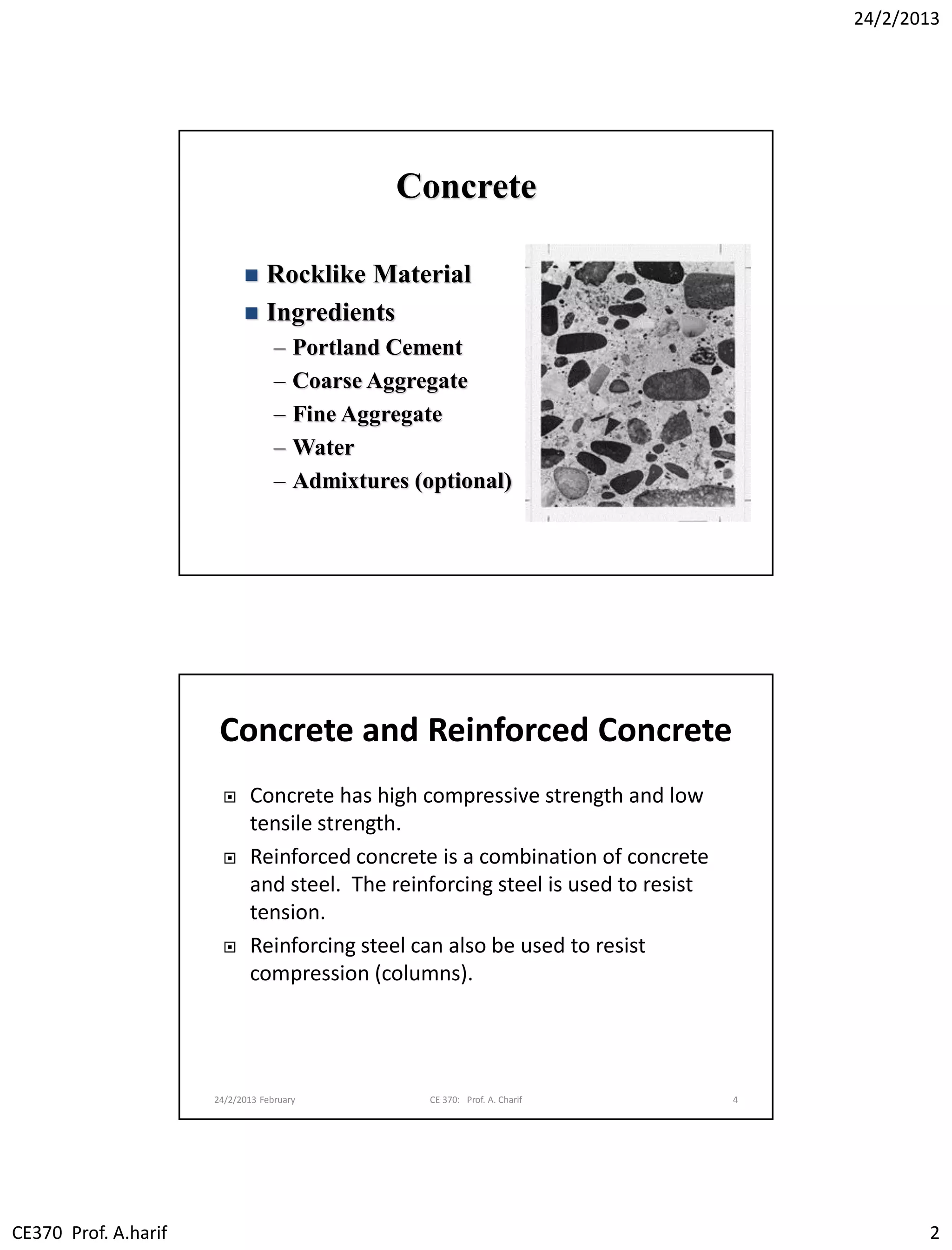
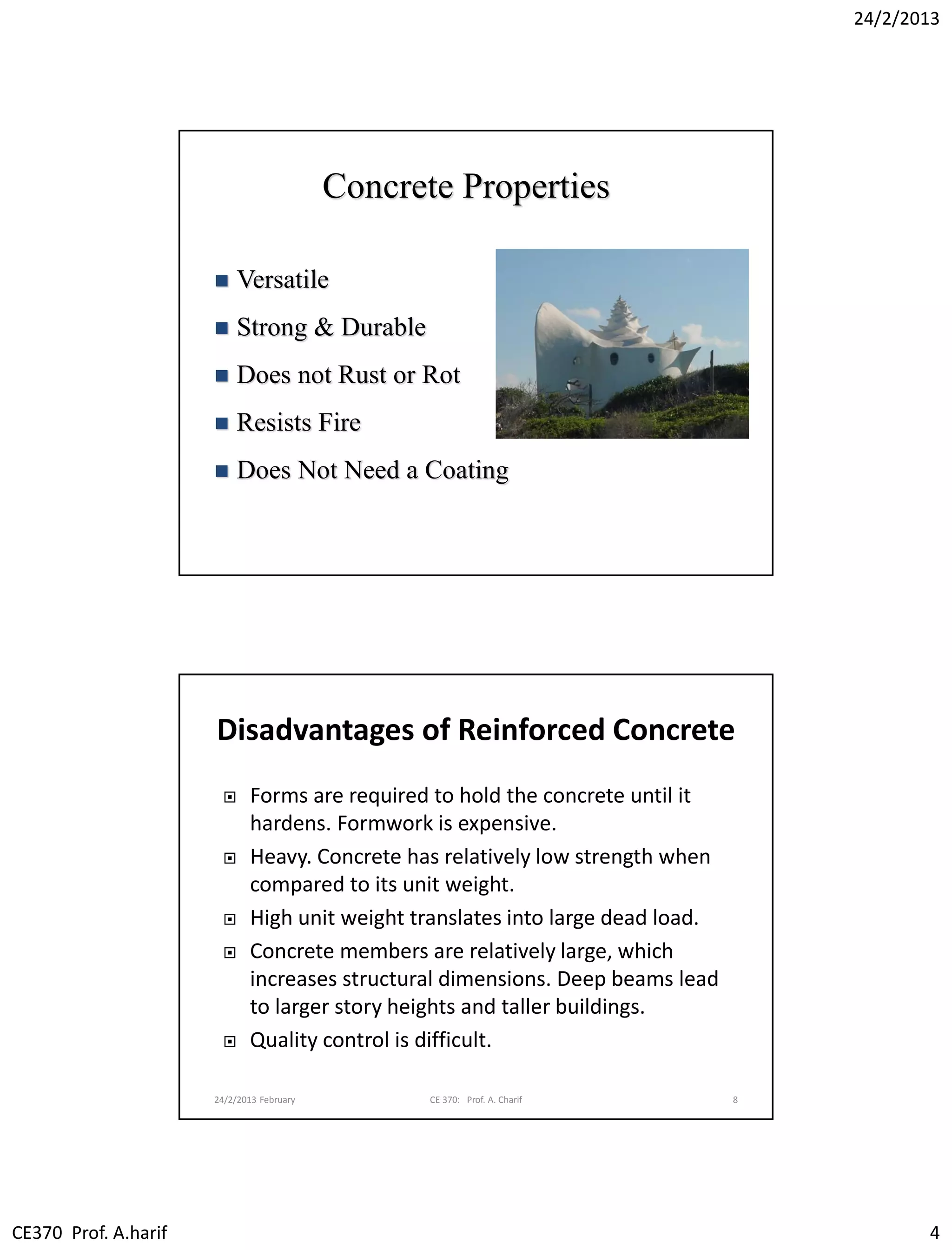
The document provides an introduction to reinforced concrete design, covering its composition, advantages, disadvantages, and the importance of building codes in the design process. It explains the different limit states (ultimate, serviceability, special) and the design philosophy that ensures structures can safely withstand loads, including guidance on the working stress and ultimate limit state methods. Additionally, it discusses the importance of accurately estimating various types of loads that a structure may encounter during its lifetime.